Download to read offline
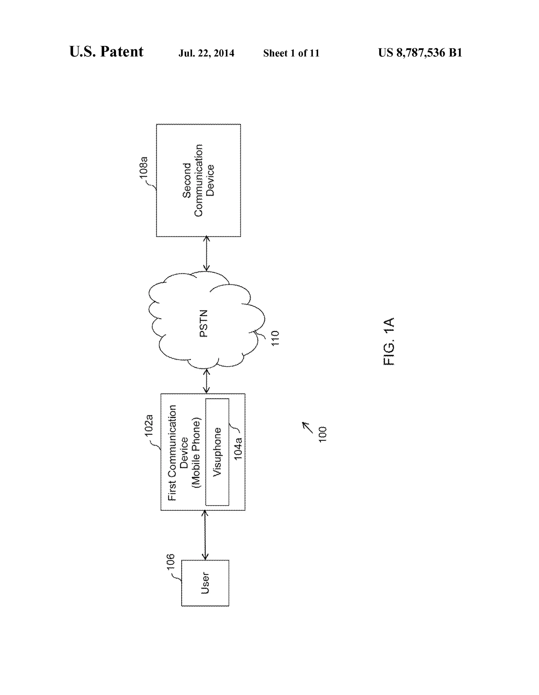
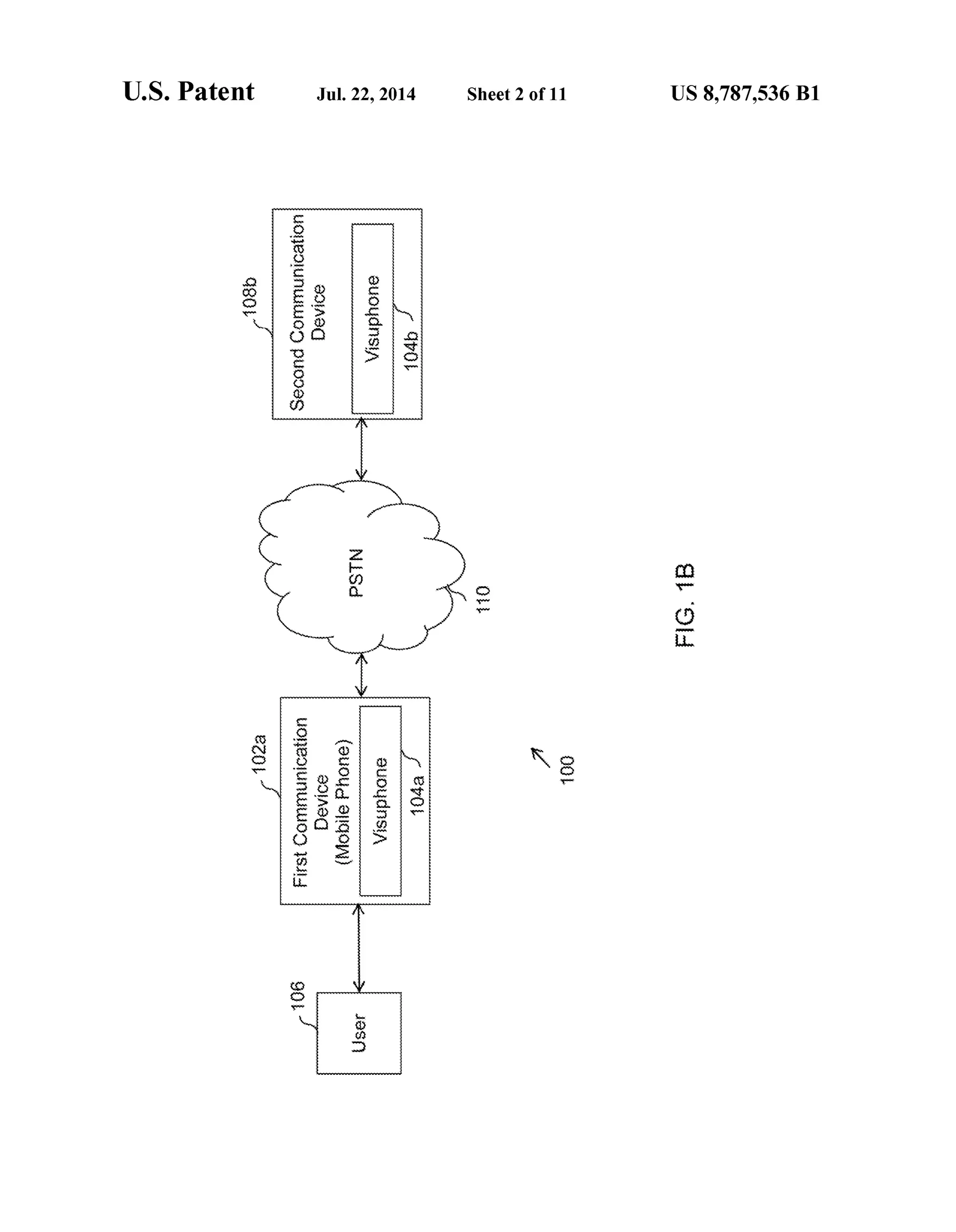
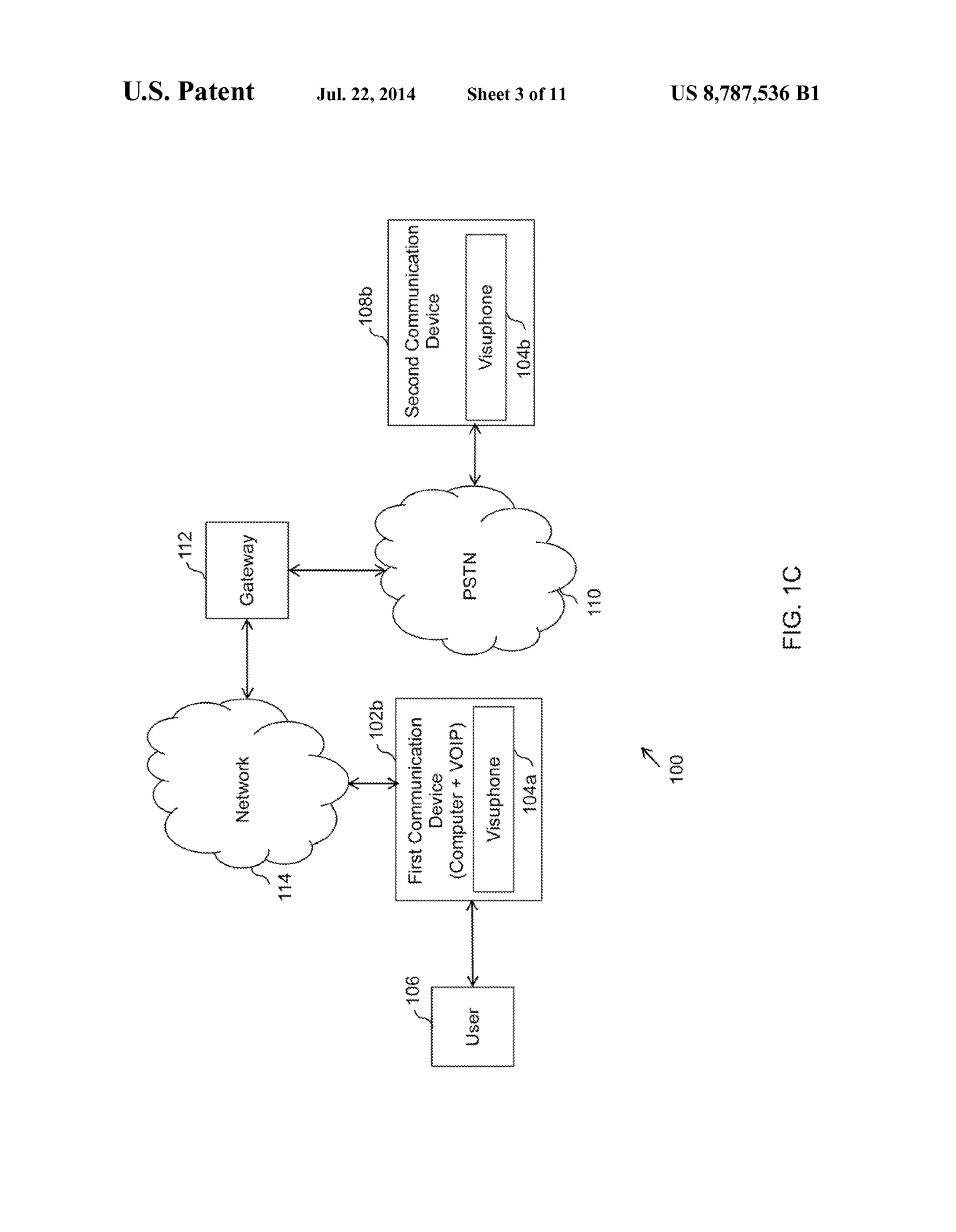
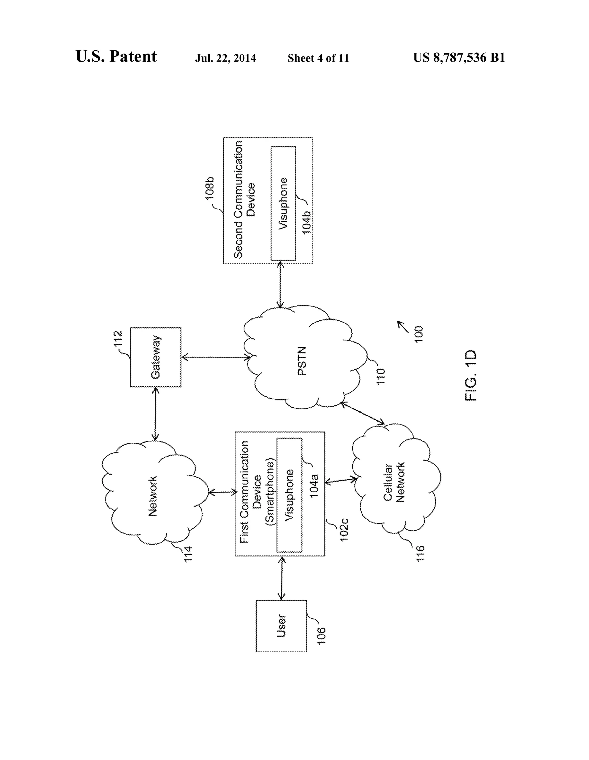
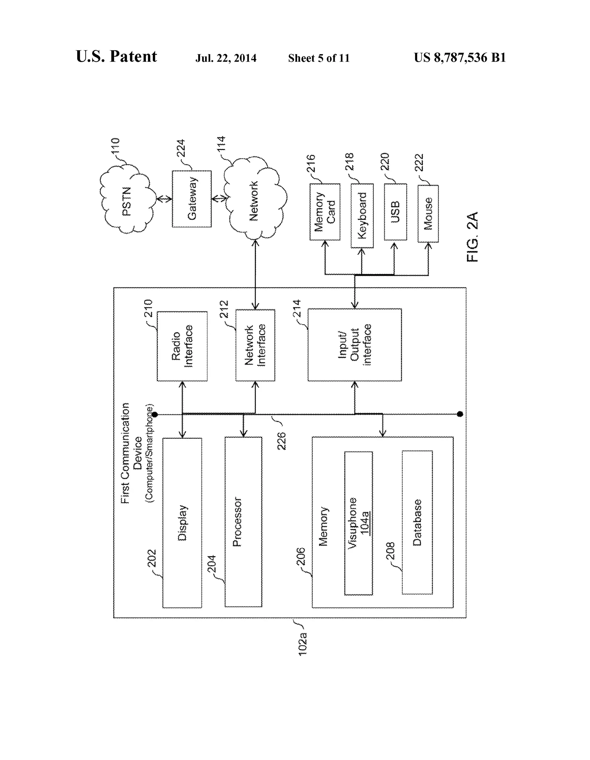
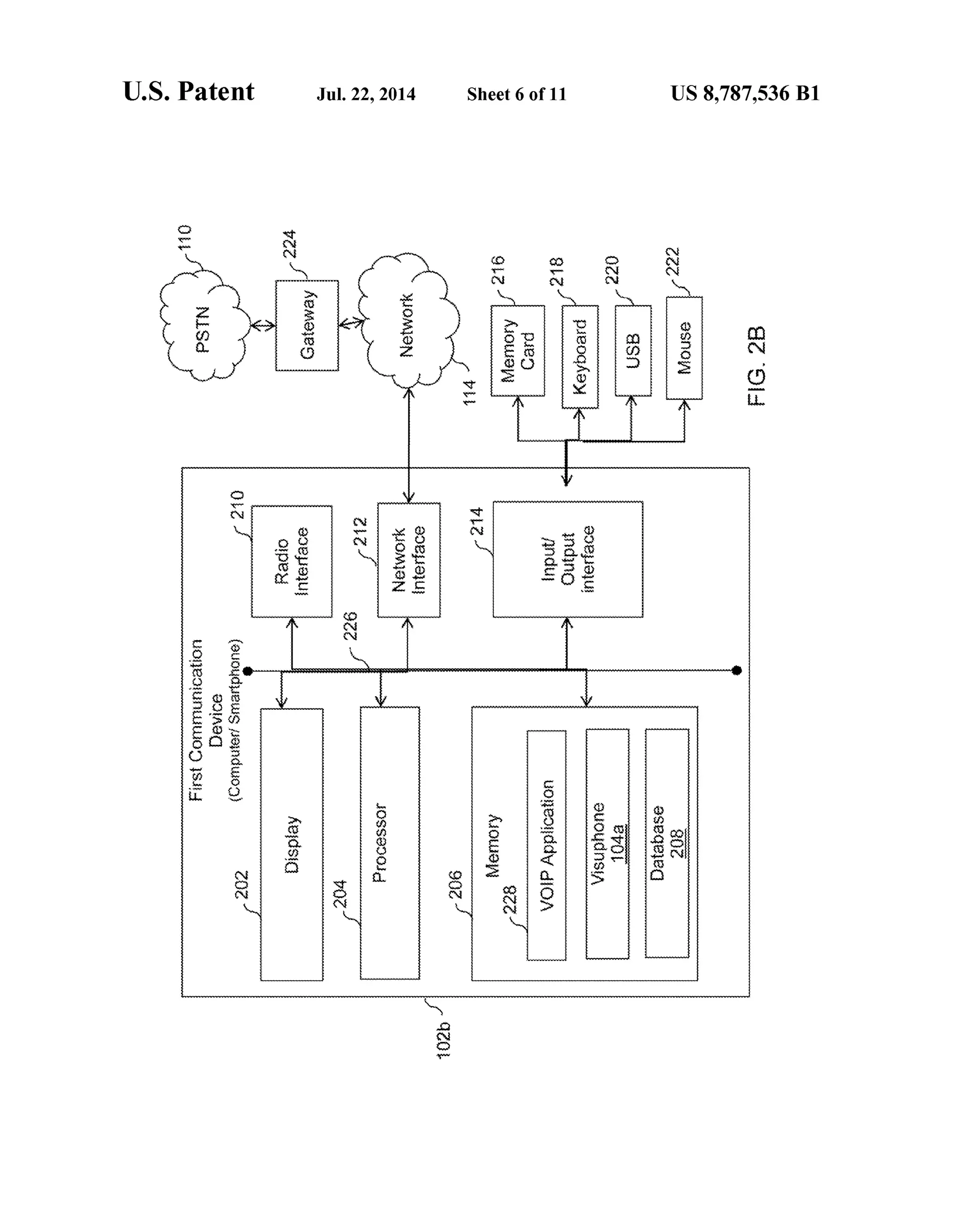
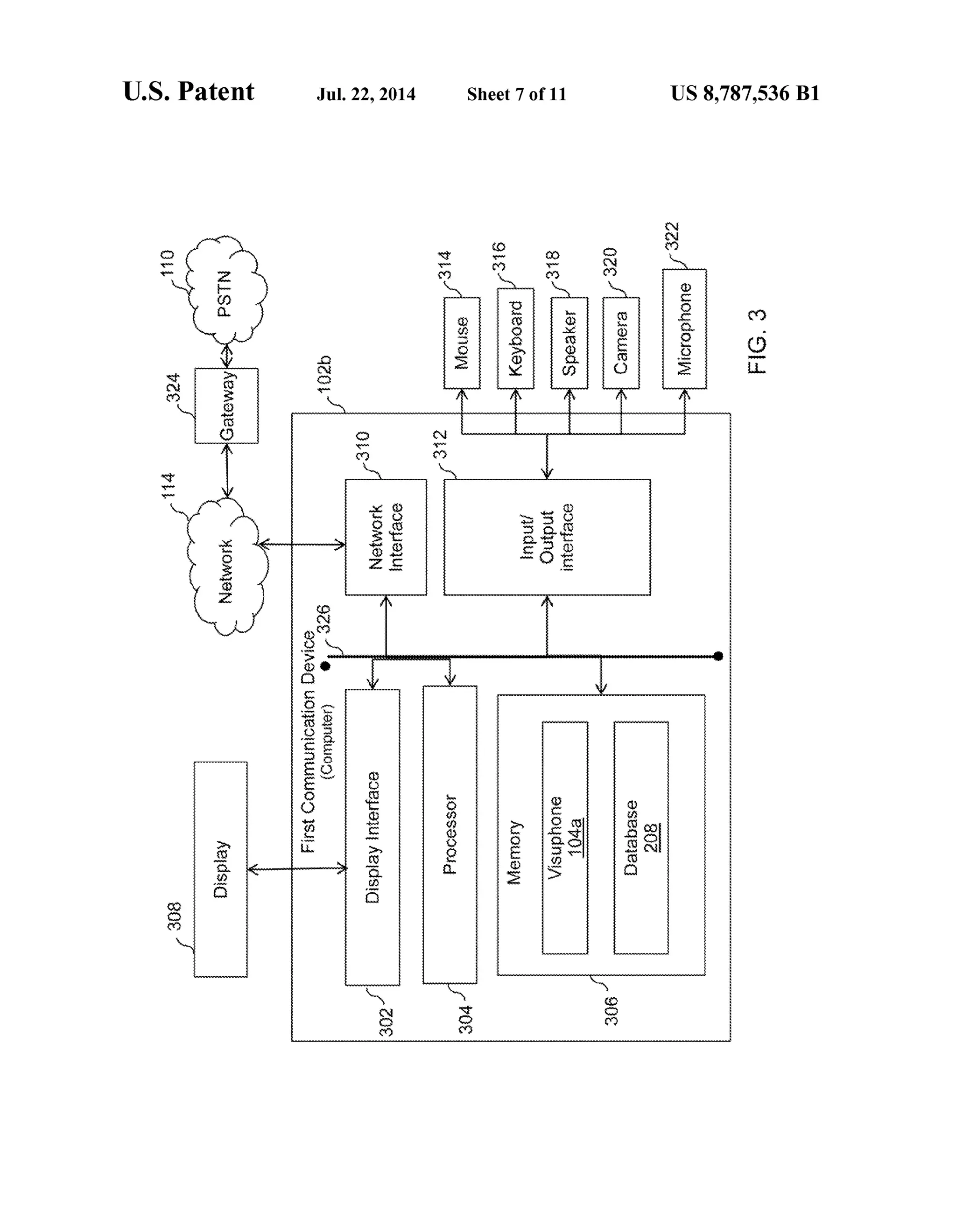

The document discusses a patent for systems and methods aimed at improving communication with interactive voice response (IVR) systems. It describes a communication device capable of sending and receiving data packets based on visual IVR menus to enhance user interaction and responsiveness. The invention addresses limitations in traditional IVR systems by allowing for a more interactive experience through visual aids, thereby reducing user frustration and improving efficiency.