SlideShare a Scribd company logo
1 of 30
Download to read offline
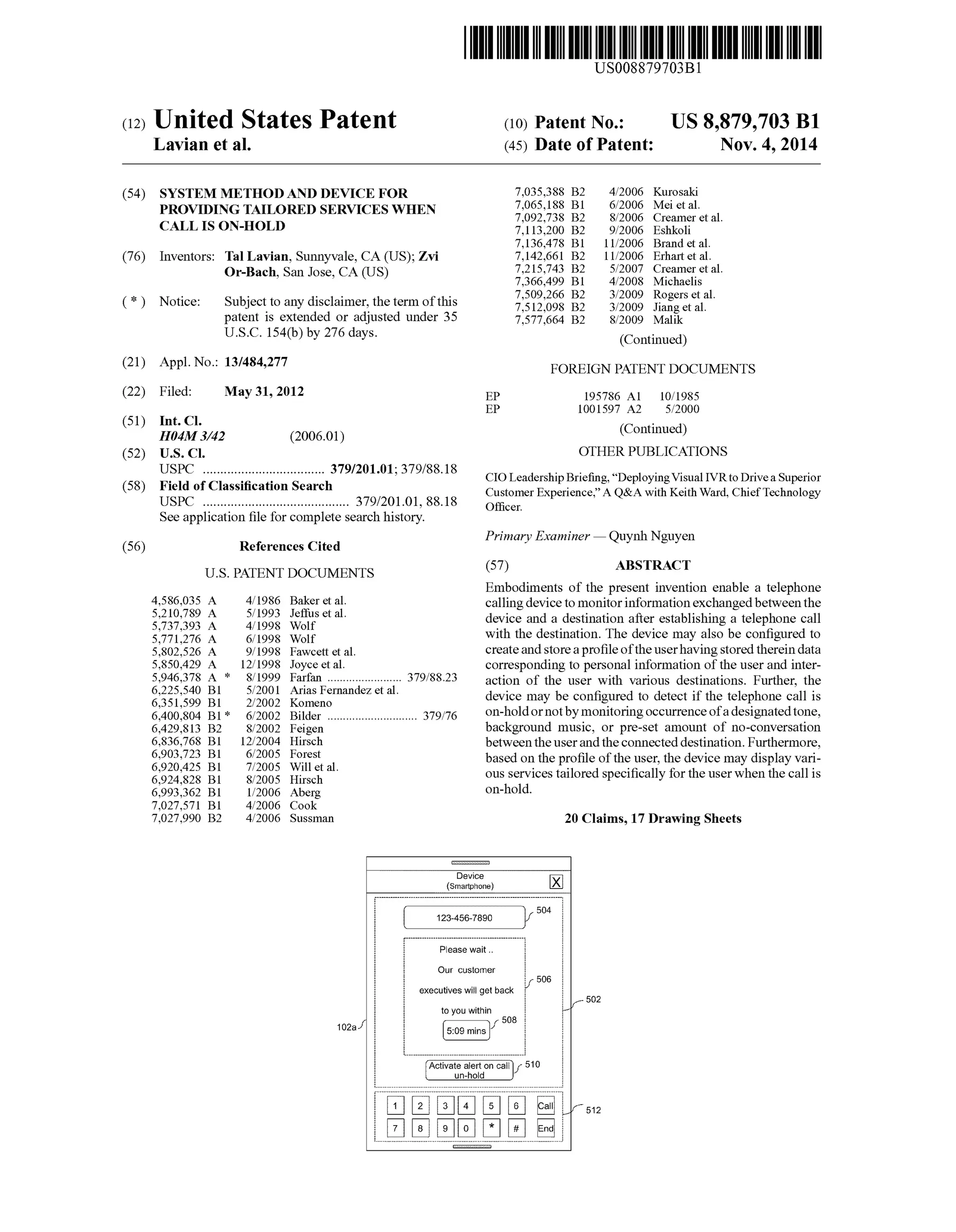
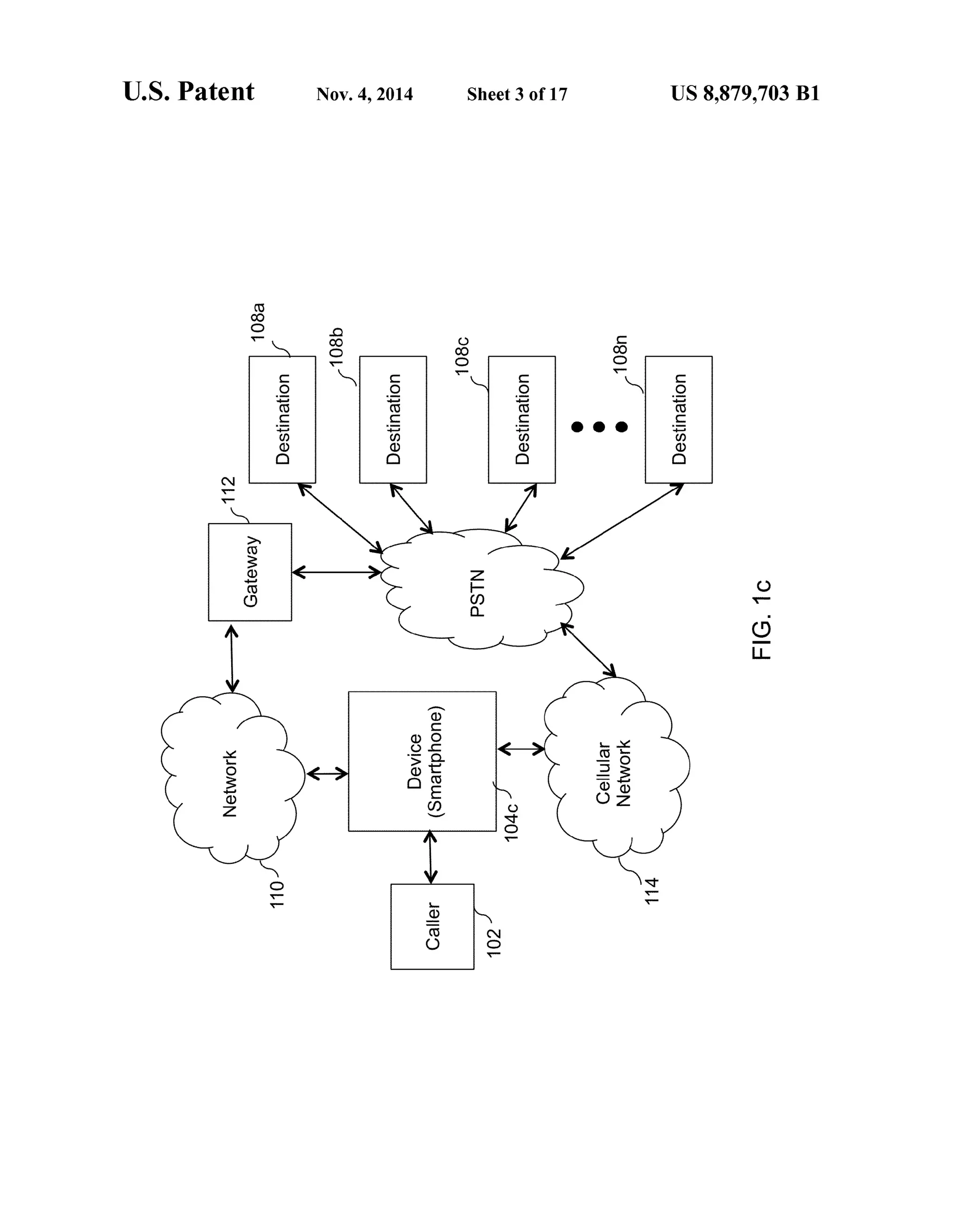
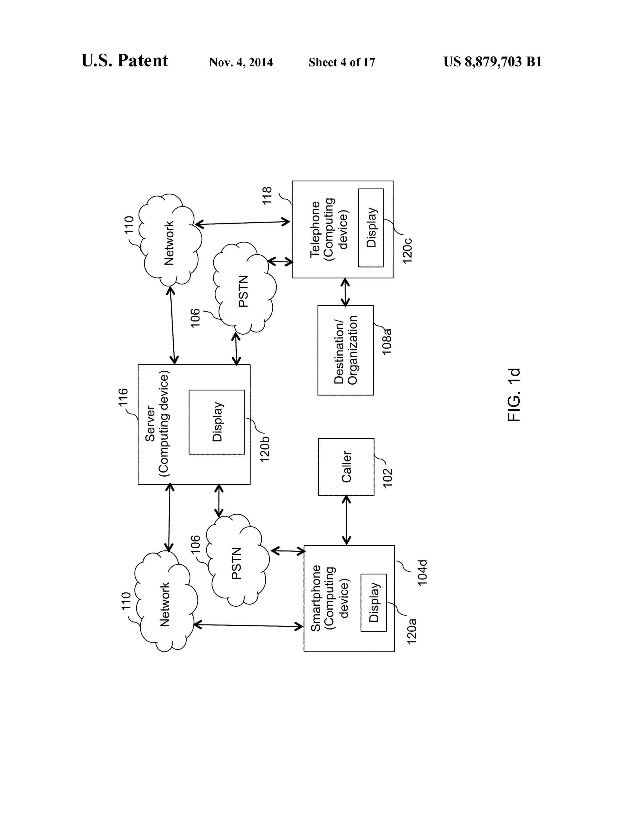
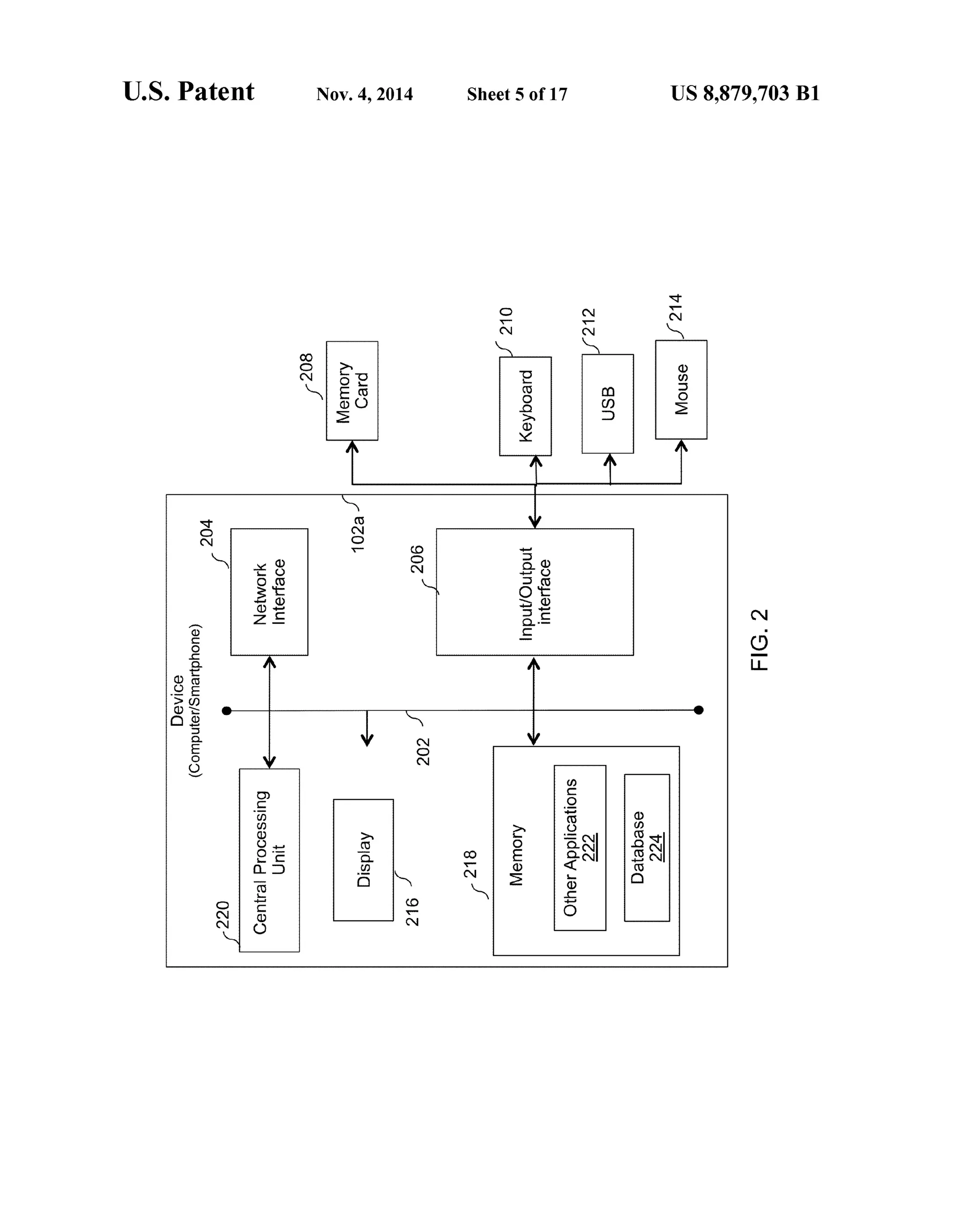
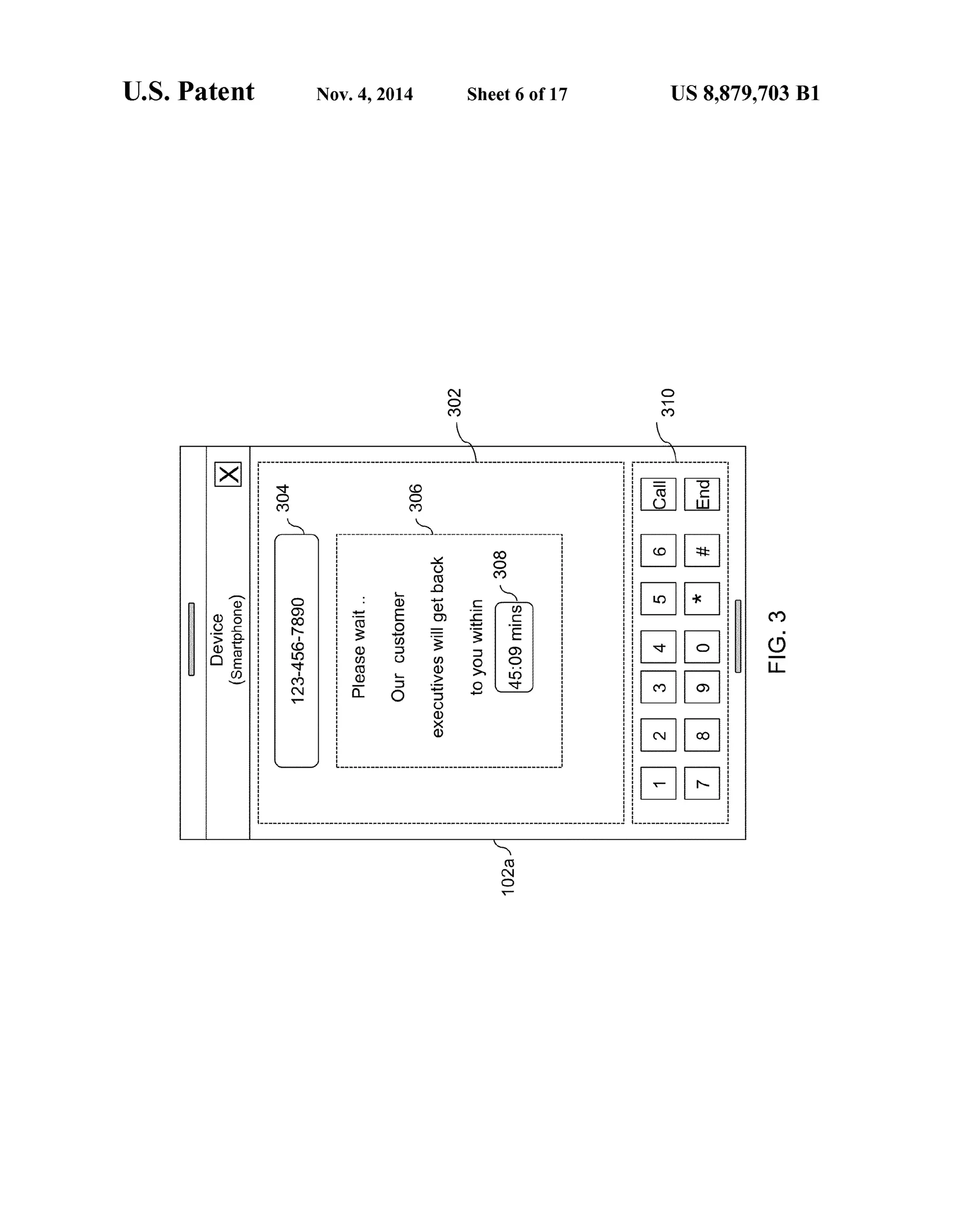
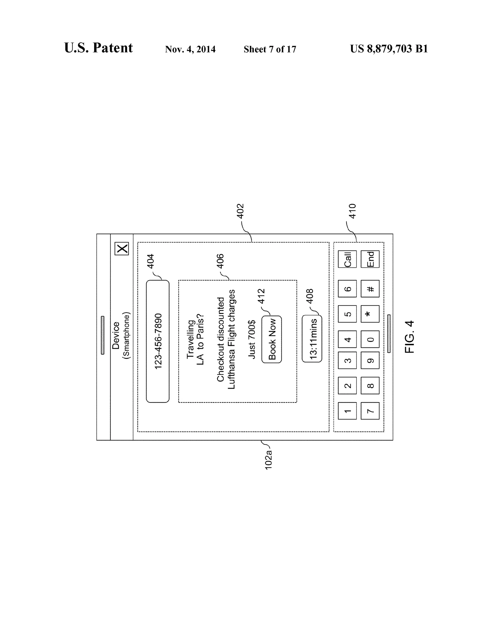
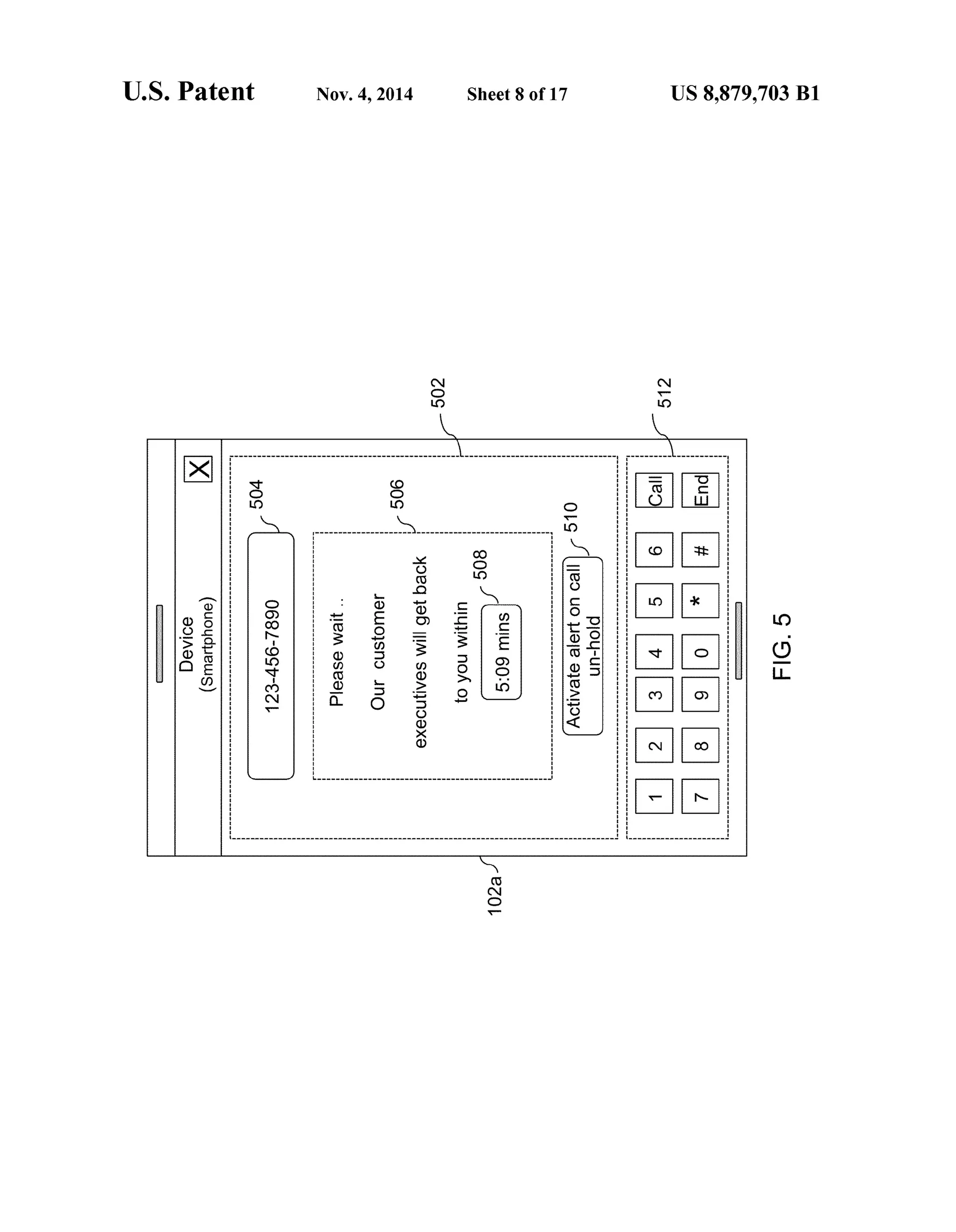
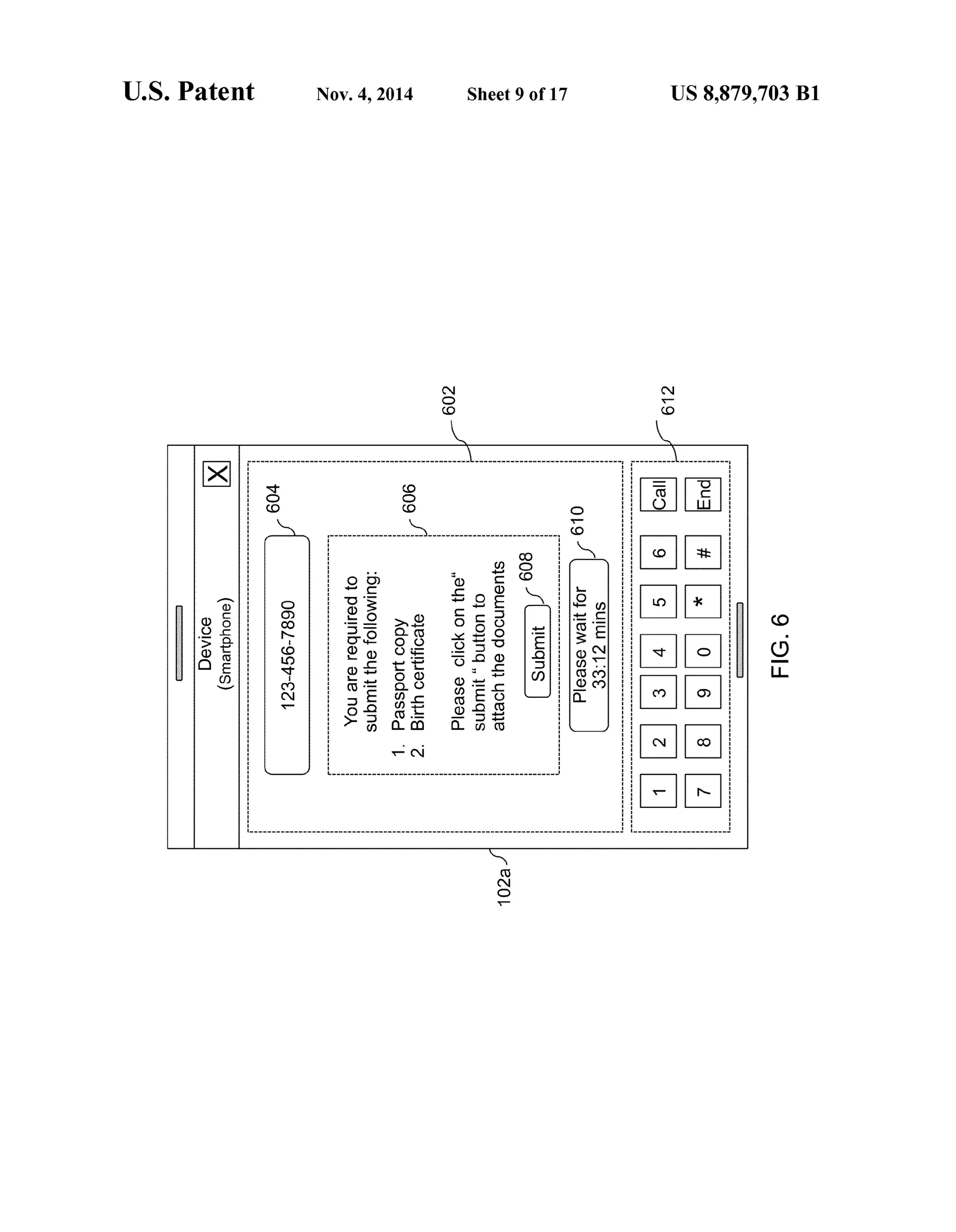
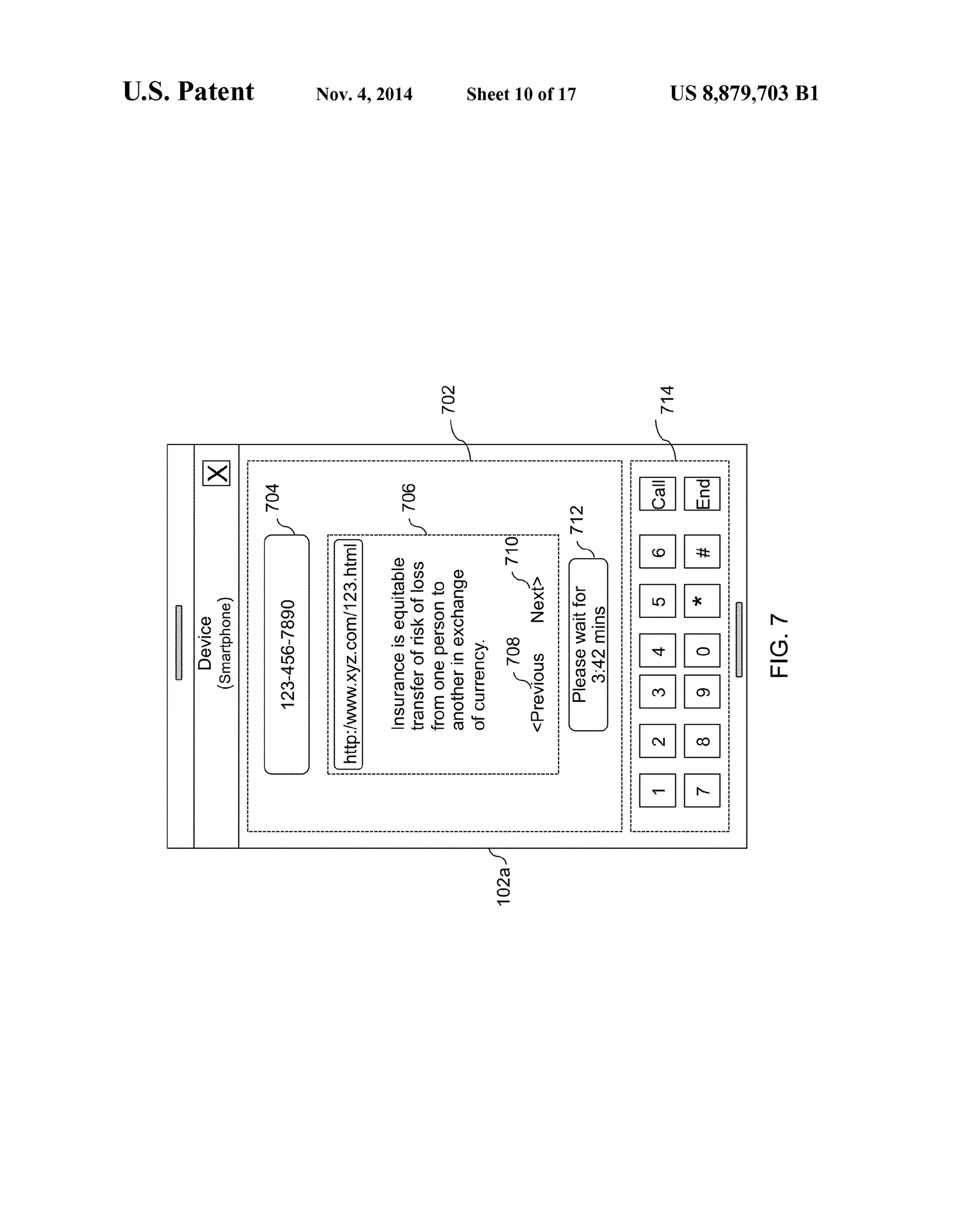
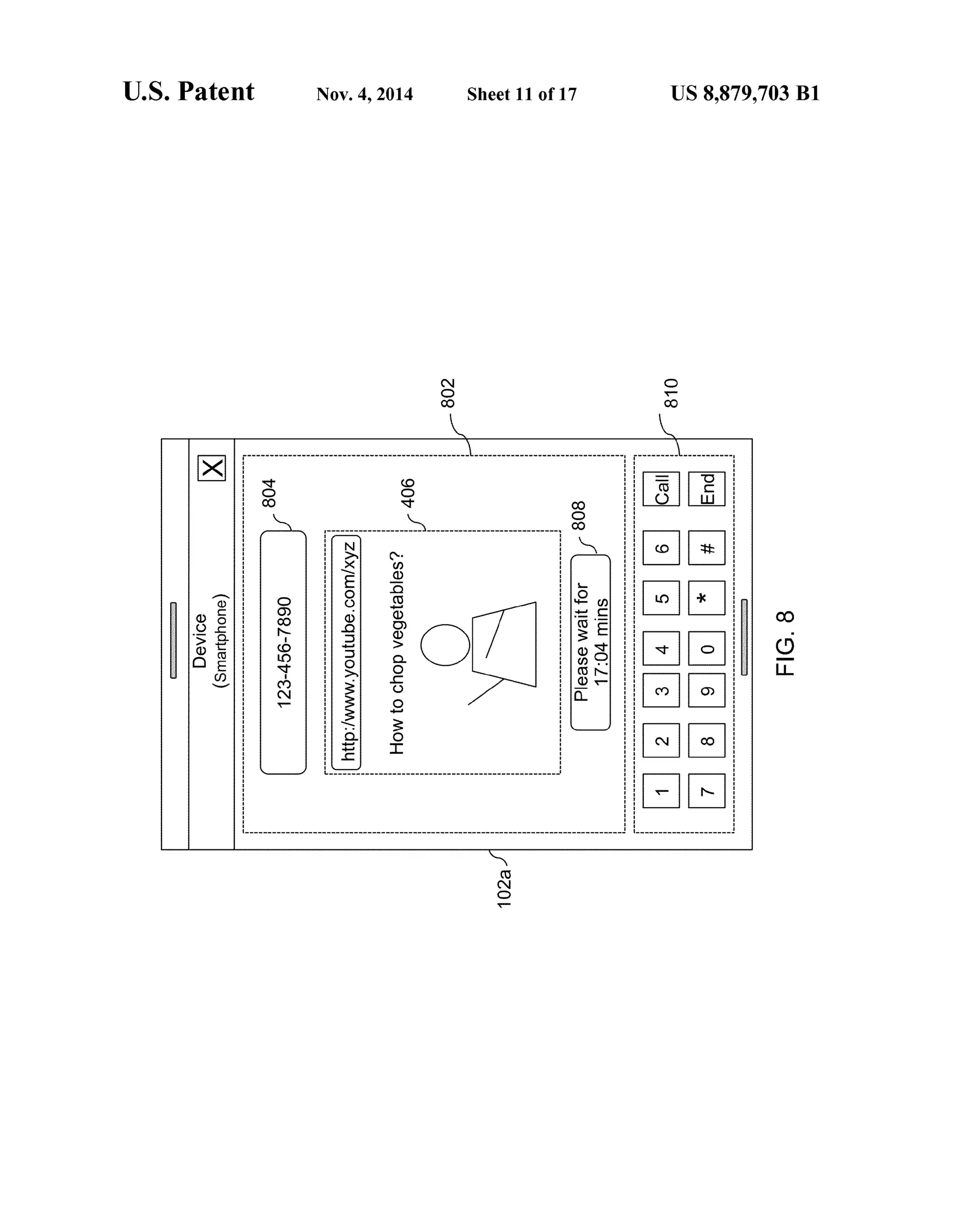
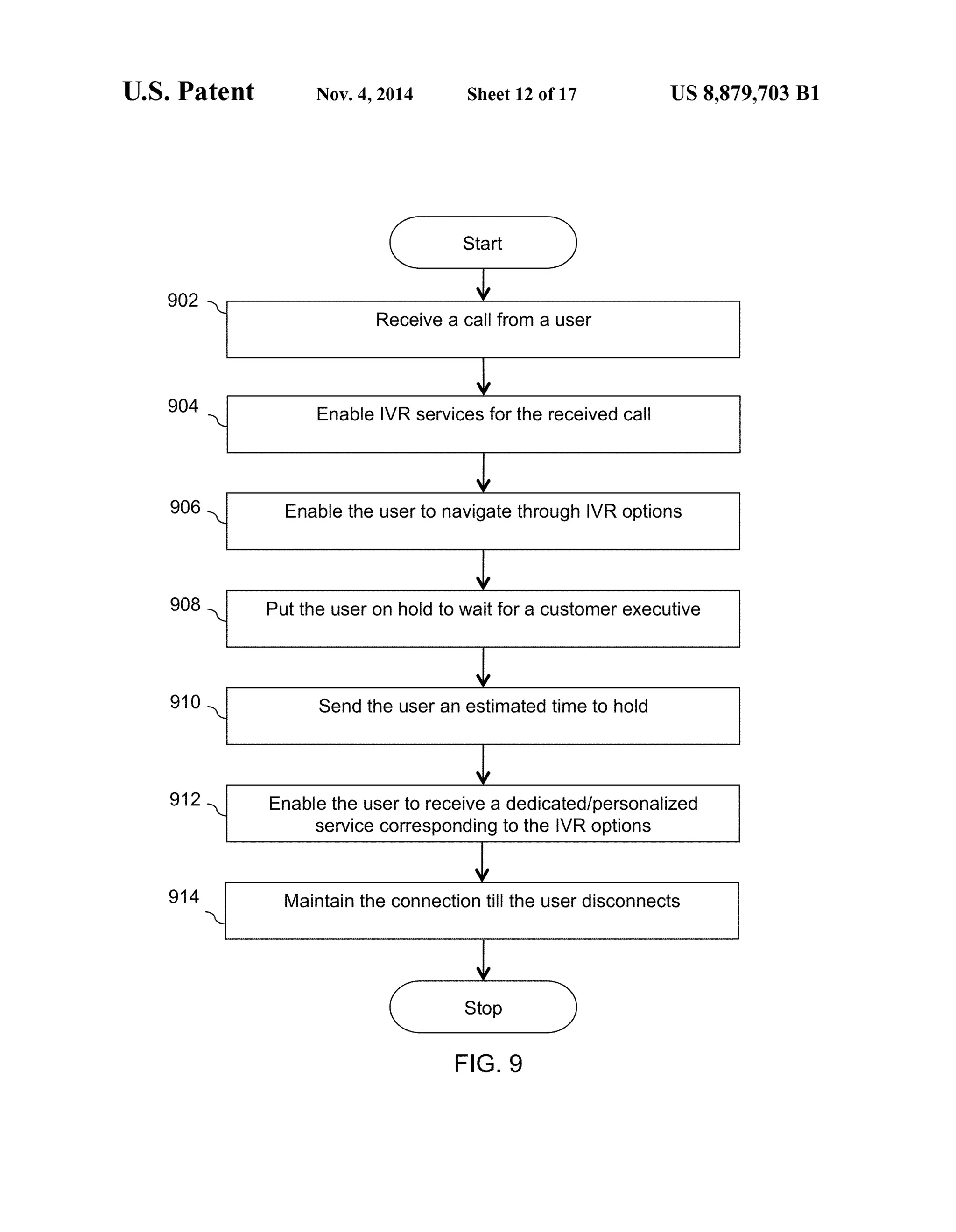
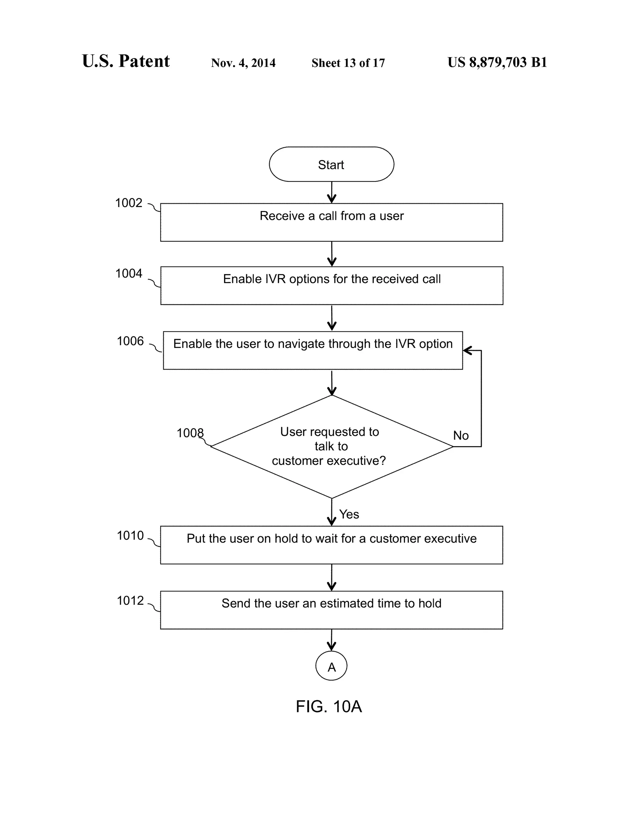
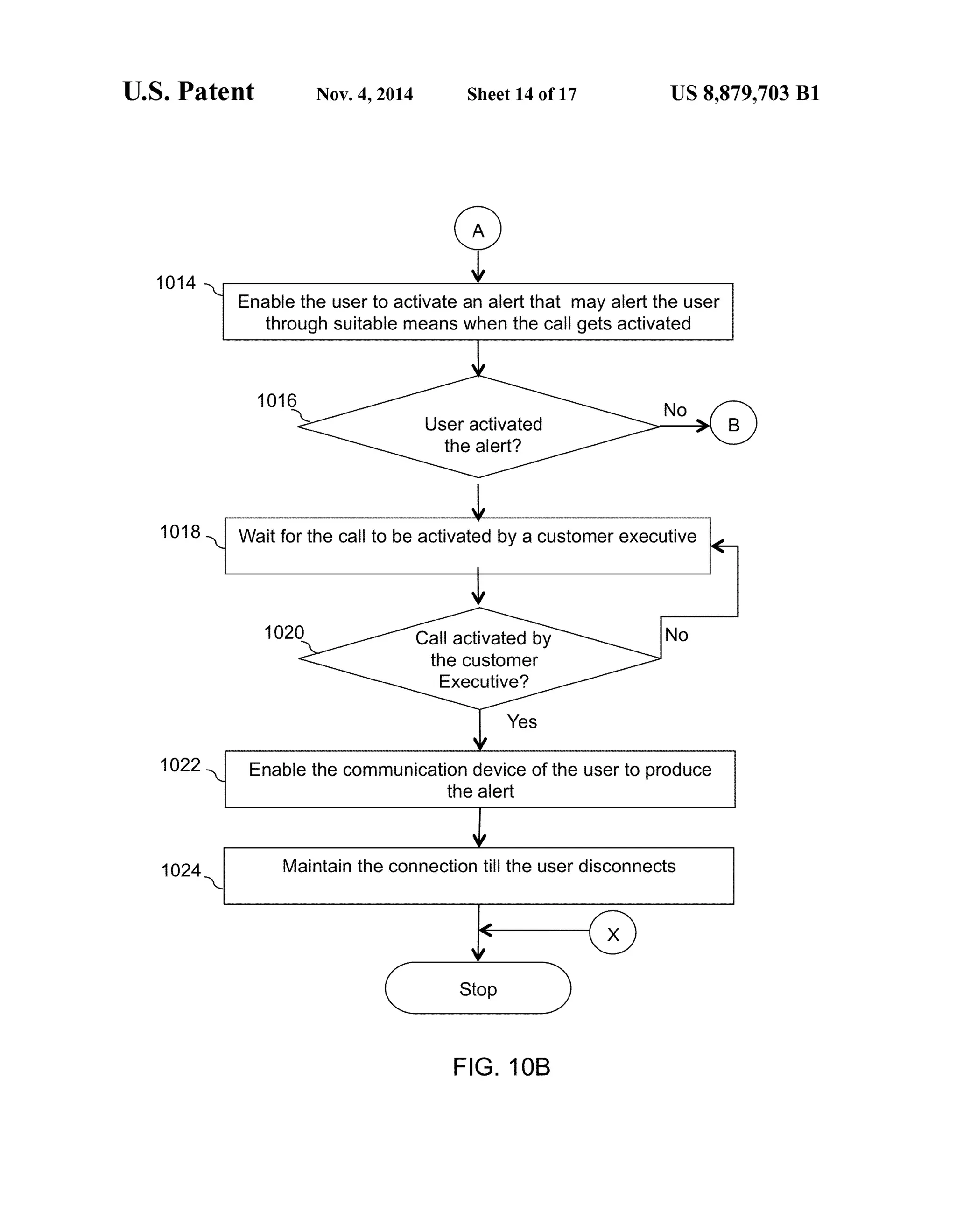
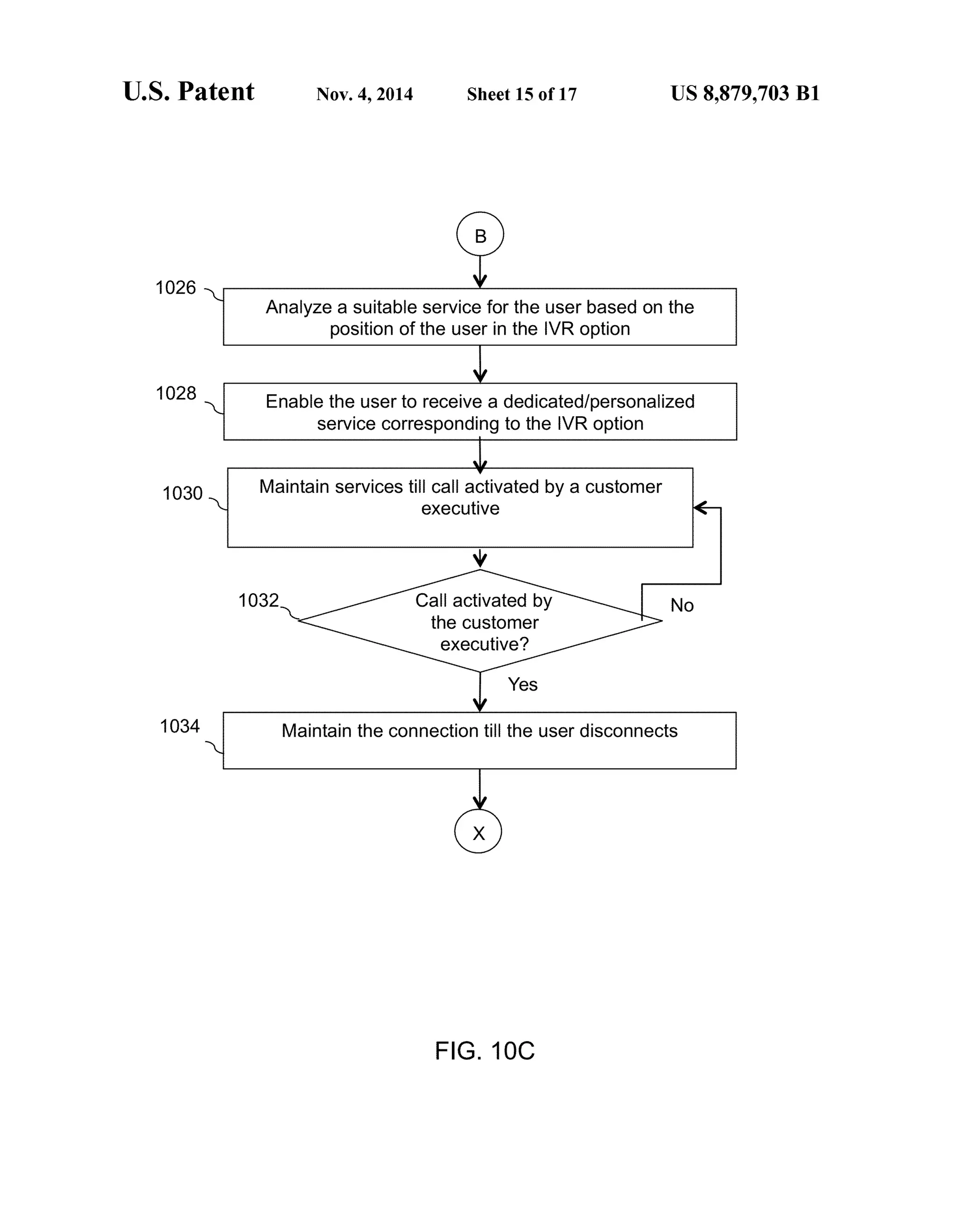
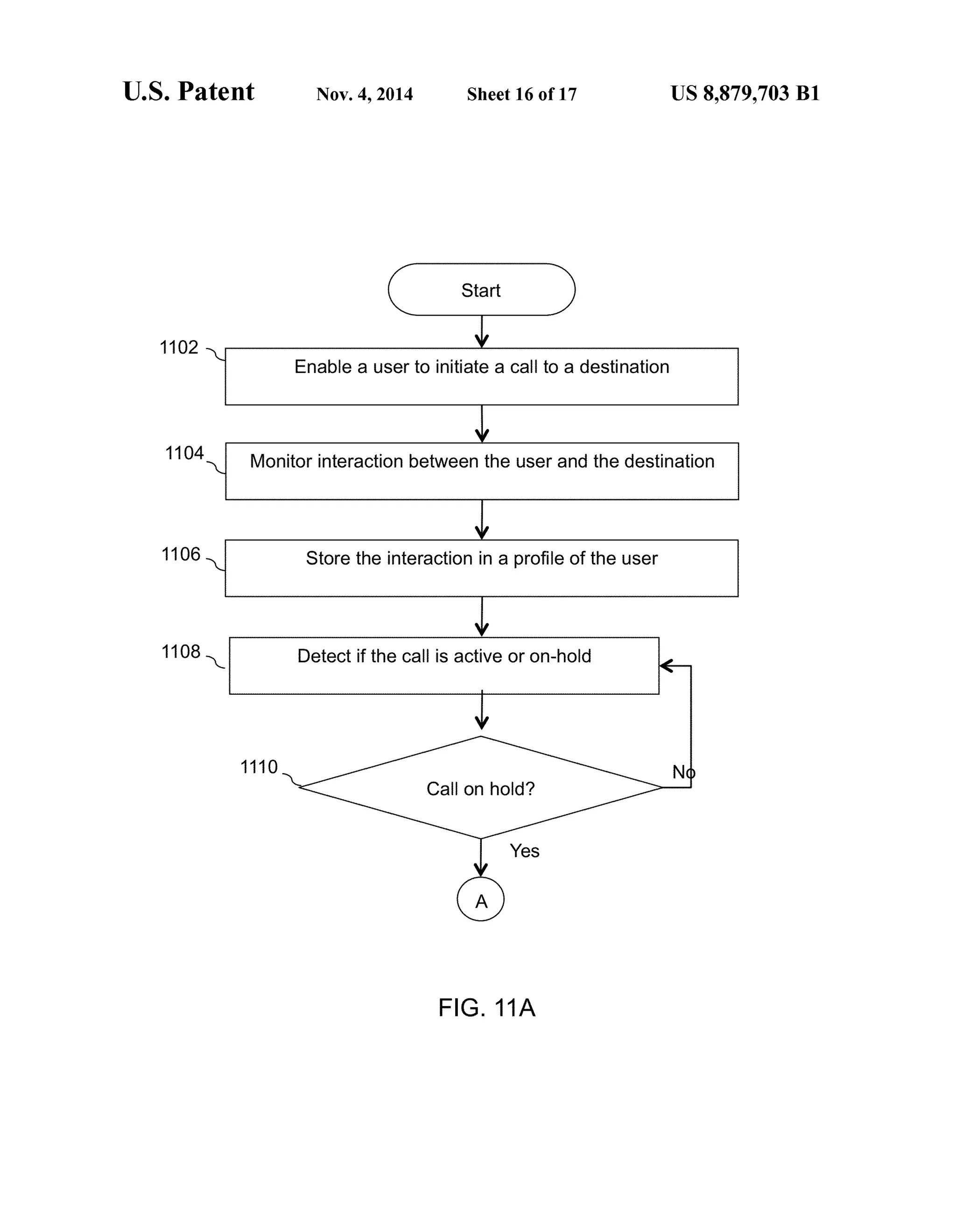
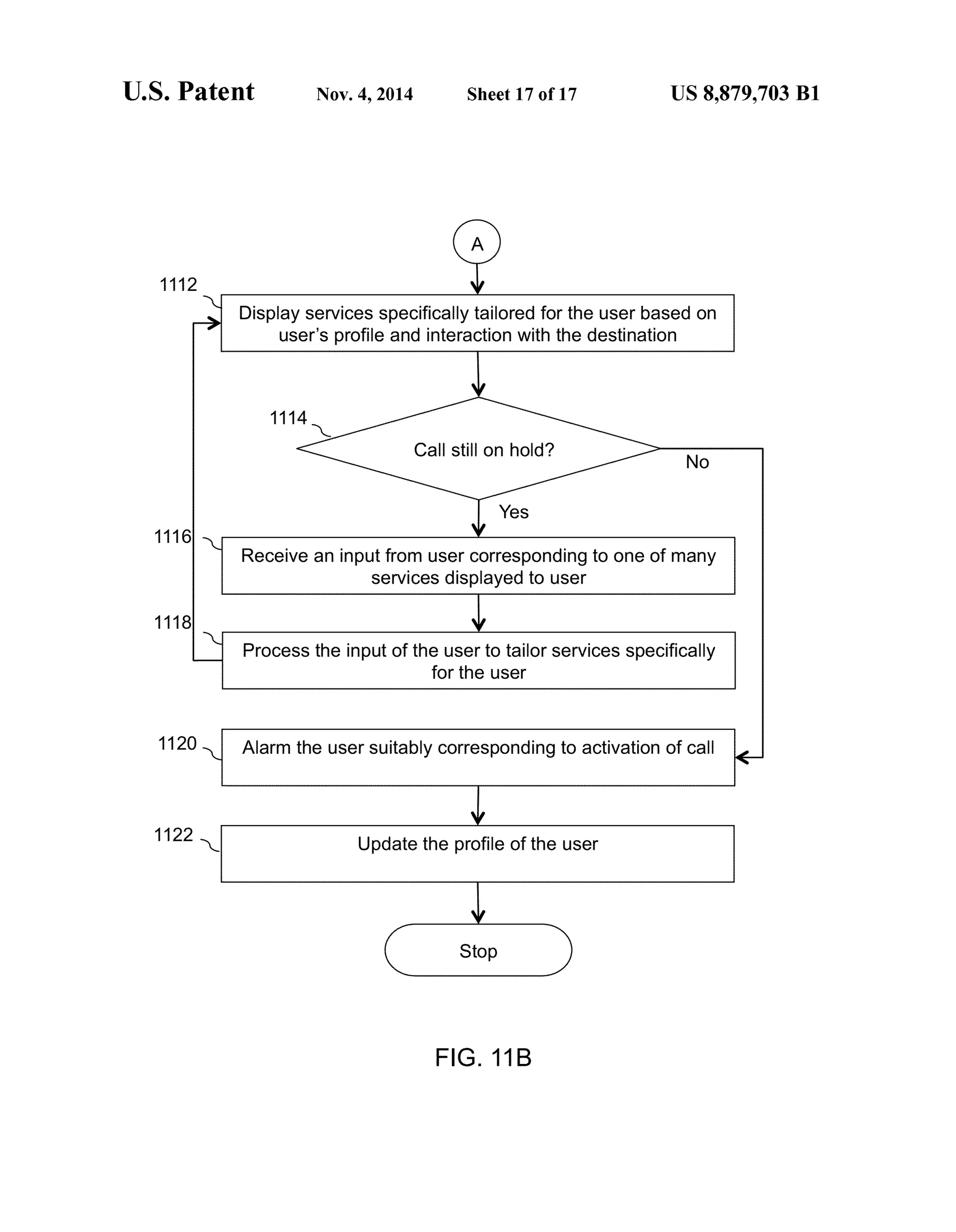
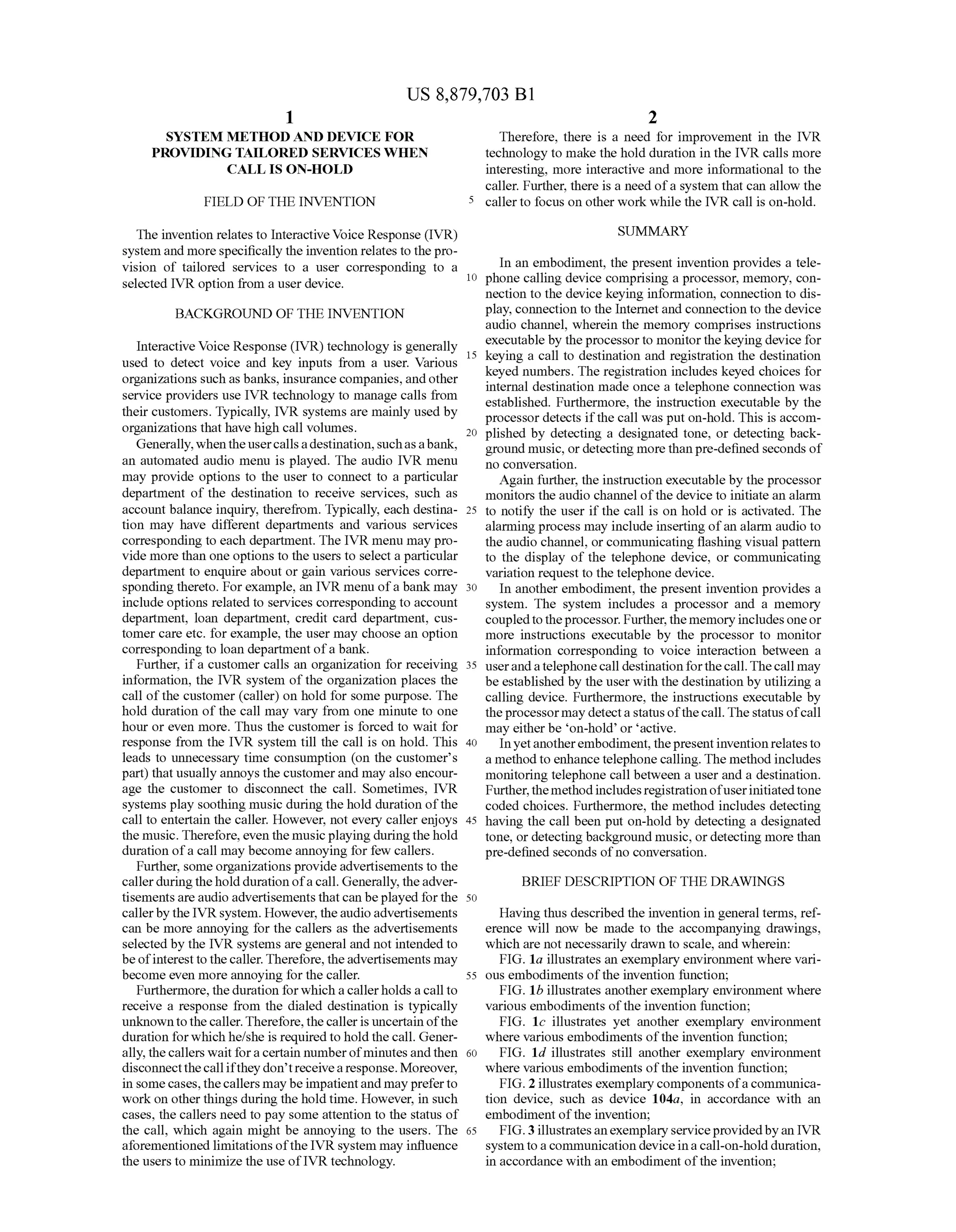
USOO8879703B1
(12) United States Patent (10) Patent No.: US 8,879,703 B1
Lavian et al. (45) Date of Patent: Nov. 4, 2014
(54) SYSTEM METHODAND DEVICE FOR 23. 38. St.ei et al.
PROVIDING TAILORED SERVICES WHEN 7,092,738 B2 8/2006 Creamer et al.
CALLIS ON-HOLD 7,113,200 B2 9/2006 Eshkoli
7,136,478 B1 1 1/2006 Brand et al.
(76) Inventors: Tal Lavian, Sunnyvale, CA (US); Zvi 7,142,661 B2 11/2006 Erhartet al.
Or-Bach, San Jose, CA (US) 7,215,743 B2 5/2007 Creamer et al.
s s 7.366,499 B1 4/2008 Michaelis
7,509,266 B2 3,2009 R. tal.
(*) Notice: Subjectto any disclaimer,the term ofthis 7,512,098 B2 3/2009 E"
patent is extended or adjusted under 35 7,577,664 B2 8,2009 Malik
U.S.C. 154(b) by 276 days. (Continued)
(21) Appl. No.: 13/484.277 FOREIGN PATENT DOCUMENTS
(22) Filed: May 31, 2012 EP 195786 A1 10,1985
(51) EP 1OO1597 A2 5,2000
51) Int. Cl.
H04M 3/42 (2006.01) (Continued)
(52) U.S. Cl. OTHER PUBLICATIONS
58 fo - - - - -ificati- - - - - -s - - - - - - -h379/201.01: 379/88.18 CIO Leadership Briefing, “DeployingVisual IVRto Drivea Superior
(58) O assification Searc Customer Experience.” A Q&A with Keith Ward, ChiefTechnology
USPC .......................................... 379/201.01, 88.18 Officer.
Seeapplication file forcomplete search history.
Primary Examiner — OuVnh Nguven
(56) References Cited y Quy glly
4,586,035 A 4, 1986 Baker et al. callingdeviceto monitorinformation exchangedbetween the
2.93. A 38. sy etal. device and a destination after establishing a telephone call
5,771276 A 6, 1998 Wolf with the destination. The device may also be configured tO
5,802,526 A 9, 1998 Fawcett et al. createandstoreaprofileoftheuserhavingStoredtherein data
5,850,429 A 12/1998 Joyce etal. corresponding to personal information ofthe userand inter
5,946,378 A * 1999 Farfan.dez etal. 379.88.23 action of the user with various destinations. Further, the
359 R 58. Esman eZ etal. device may be configured to detect if the telephone call is
6400804 B1* 62002 Bilder. 379.76 on-holdornotbymonitoringoccurrenceofadesignatedtone,6,429,813 B2 8/2002 Feigen background music, or pre-set amount of no-conversation
6,836,768 B1 12/2004 Hirsch betweentheuserandtheconnected destination. Furthermore,
3:63 R $39. Wil,al based on the profile ofthe user, the device may display vari
6,924.82s Bl 8,2005 I ous services tailored specifically forthe userwhen the call is
6,993,362 B1 1/2006 Aberg on-hold.
7,027,571 B1 4/2006 Cook
7,027,990 B2 4/2006 Sussman 20 Claims, 17 Drawing Sheets
Device
(she) X
; Pease wait..
Our customer i-506
executives wi getback p? 5O2
toyou within -
102a
U.S. PATENT DOCUMENTS (57) ABSTRACT
Embodiments of the present invention enable a telephone
508
Activate aert on ca.
un-hod
US 8,879,703 B1
Page 2
(56) References Cited 2010,01661.58 A1 7,2010 Costello et al.
2010/0168996 A1 7/2010 Bourque et al.
U.S. PATENT DOCUMENTS 2010, 0169098 A1 7,2010 Patch
2010, O2381 15 A1 9/2010 Komaarashi et al.
7.590,943 B2 9/2009 Bailey etal. 2011/0009096 A1 1/2011 RotSztein etal.
7,602,888 B2 10/2009 Vu 2011 OO14952 A1 1/2011 Minton
7,603,627 B2 10/2009 Bailey etal. 2011/O125911 A1 5/2011 Koch et al.
7,657,005 B2 2/2010 Chang 2011/0225.330 A1 9,2011 Lavian et al.
7,717,712 B2 52010 Brun etal. 2011/0301943 A1 12/2011 Patch
7,752,560 B2 7/2010 Bailey etal. 2012.0056752 A1 3,2012 Baldwin et al.
7,881,703 B2 2/2011 Roundtree et al.
7,882,115 B2 2/2011 Hirsch
8,000,454 B1 8, 2011 Or-Bach et al.
2012/009581.0 A1 4/2012 Miao et al.
2012/0110490 A1 5,2012 Keller et al.
8,054,952 B1 1 1/2011 Or-Bach et al. 2012/0136783 A1 5,2012 Pousti
8,150,699 B2 4,2012 Patch
8,155,280 B1 4/2012 Or-Bach et al. FOREIGN PATENT DOCUMENTS
8,160,215 B2 4/2012 Or-Bach et al.
8,175,651 B2 5, 2012 Rios et al. EP 1003153 A1 5,2000
8,223,929 B2 7/2012 Sylvain EP 1610536 A1 12/2005
8,223,931 B1 7/2012 Lavian et al. EP 82577O B1 4/2008
8,265,234 B2 9/2012 Singh EP 2O39137 A2 3,2009
2002fOO2323.0 A1 2/2002 Bolnicket al. EP 223.0582 A2 9,2010
2002/O120932 A1 8, 2002 Schwalb GB 233.1170 A 5, 1999
2002/0194264 Al 12/2002 Uchiyama etal. GB 233,2972 A 7, 1999
2003,0005076 A1 1/2003 Koch et al. WO 9630822 A1 10, 1996
2003/0103075 A1 6, 2003 Rosselot WO 9943 159 A1 8, 1999
2003/0179231 A1 9/2003 Kamiwada et al. WO 99.43160 A1 8, 1999
2004/O122941 A1 6/2004 Creamer et al. WO 0065483 A2 11/2000
2004/0236620 A1 11/2004 Chauhan et al. WO 0211072 A1 2,2002
2005/0231520 A1 10,2005 Forest WO 2004055647 A2 T 2004
2005/0288973 A1 12/2005 Taylor et al. WO 2004.104891 A1 12/2004
2006/0200569 A1 9, 2006 Koch et al. WO 2006123910 A1 11 2006
2007/0043687 A1 2/2007 Bodart et al. WO 2006125257 A1 11,2006
2007/O135101 A1 6, 2007 Ramati et al. WO 2007O24704 A2 3,2007
2007/0286162 A1 12,2007 Fabbrizio et al. WO 2008OO2705 A2 1,2008
2008.0030463 A1 2/2008 Forest WO 2008144557 A1 11 2008
2008.003905.6 A1 2/2008 Mathews et al. WO 2008144638 A2 11/2008
2008/0066015 A1 3/2008 Blankenhorn WO 20090792.52 A1 6,2009
2008/0095330 A1 4/2008 Jin et al. WO 2009100477 A1 8,2009
2008. O162628 A1 7,2008 Hill et al. WO 2010.076327 A1 T 2010
2008. O169944 A1 7/2008 Howarth et al. WO 201100.7262 A1 1,2011
2008/0304639 A1 12/2008 McDonough et al. WO 2011046693 A1 4/2011
2009,01964.05 A1 8, 2009 Romeo WO 2012O10217 A1 1,2012
2009/02O7980 A1 8/2009 Bergeret al. WO 2012026744 A2 3,2012
2009,0276441 A1 11,2009 Malik
2010.0011315 A1 1/2010 Araki * cited by examiner
US 8,879,703 B1
agolº
U.S. Patent
US 8,879,703 B1U.S. Patent
US 8,879,703 B1Sheet 3 of 17Nov. 4, 2014U.S. Patent
(
US 8,879,703 B1Sheet 4 of 17Nov. 4, 2014U.S. Patent
OOZ).
ZO
US 8,879,703 B1
goz/
U.S. Patent
?•••••••••••••••••••????????????????
US 8,879,703 B1
0||9
;-------------------------------------------------------------------------------------+(ououdueus)
U.S. Patent
US 8,879,703 B1Sheet 7 Of 17Nov. 4, 2014U.S. Patent
cos
a
---------------------------------------------------
US 8,879,703 B1Sheet 9 Of 17Nov. 4, 2014U.S. Patent
US 8,879,703 B1Sheet 10 of 17Nov. 4, 2014U.S. Patent
wereasses----------------------------------------
CO
O
N.
US 8,879,703 B1Sheet 11 of 17Nov. 4, 2014U.S. Patent
Z09
90°/?
{------------------------------------------------------}
U.S. Patent Nov. 4, 2014 Sheet 12 of 17 US 8,879,703 B1
902
Receive a Call from a user
906 Enable the userto navigate through IVR options
912 Enable the user to receive a dedicated/personalized
service corresponding to the IVR options
Maintain the COnnection till the user disCOnnects914
FIG. 9
U.S. Patent Nov. 4, 2014 Sheet 13 of 17 US 8,879,703 B1
10O2
Receive a Call from a user
1004 Enable IVR options for the received call
1006 - Enabletheuserto navigatethroughthe IVRoption
User requested to
talk to
Customer executive?
1010 Put the user on hold to Wait for a Customer executive
Send the user an estimated time to hold1012
FIG. 1 OA
U.S. Patent Nov. 4, 2014 Sheet 14 of 17 US 8,879,703 B1
1014
Enable the userto activate an alert that may alert the user
through suitable means when the call gets activated
1016
User activated
the alert?
Wait for the call to be activated by a customer executive
102O
1018
Call activated by
the Customer
Executive?
1022 Enable the communication device ofthe user to produce
the alert
Maintain the Connection till the user disconnects1024
FIG. 1 OB
U.S. Patent Nov. 4, 2014 Sheet 15 Of 17 US 8,879,703 B1
1026
Analyze a suitable service for the user based on the
position ofthe user in the IVR option
1028 Enable the userto receive a dedicated/personalized
service corresponding to the IVR option
1030 Maintain services till call activated by a customer
executive
V
Call activated by
the Customer
executive?
1032
Yes
Maintain the Connection till the user disconnects1034
FIG. 10C
U.S. Patent Nov. 4, 2014 Sheet 16 of 17 US 8,879,703 B1
1102
Enable a user to initiate a Call to a destination
1104 Monitor interaction between the user and the destination
1106 Store the interaction in a profile ofthe user
1108- Detect if the Call is active or On-hold
1110
FIG. 11A
U.S. Patent Nov. 4, 2014 Sheet 17 Of 17 US 8,879,703 B1
Display services specifically tailored forthe userbased on
user's profile and interaction with the destination
1112
1114
Call still on hold?
NO
Yes
1116
Receive an input from user corresponding to one of many
services displayed to user
1118
Process the input ofthe user to tailor services specifically
for the user
1120 Alarm the user suitably Corresponding to activation of call
1122 Update the profile ofthe user
Stop
FIG 11B
US 8,879,703 B1
1.
SYSTEMI METHOD AND DEVICE FOR
PROVIDING TALORED SERVICES WHEN
CALLIS ON-HOLD
FIELD OF THE INVENTION
The invention relates to Interactive Voice Response (IVR)
system and more specifically the invention relates to thepro
vision of tailored services to a user corresponding to a
selected IVR option from a user device.
BACKGROUND OF THE INVENTION
Interactive Voice Response (IVR) technology is generally
used to detect Voice and key inputs from a user. Various
organizations such as banks, insurance companies, andother
service providers use IVR technology to manage calls from
their customers. Typically, IVR systems are mainly used by
organizations that have high call Volumes.
Generally,whentheusercallsadestination,Suchasabank,
an automated audio menu is played. The audio IVR menu
may provide options to the user to connect to a particular
department of the destination to receive services, such as
account balance inquiry, therefrom. Typically, each destina
tion may have different departments and various services
corresponding to each department. The IVR menu may pro
vide more than one options to the users to select a particular
department to enquire about or gain various services corre
sponding thereto. For example, an IVR menu ofa bank may
include options related to services corresponding to account
department, loan department, credit card department, cus
tomer care etc. for example, the user may choose an option
corresponding to loan department ofa bank.
Further, ifa customer calls an organization for receiving
information, the IVR system of the organization places the
call ofthe customer (caller) on hold for some purpose. The
hold duration ofthe call may vary from one minute to one
hour or even more. Thus the customer is forced to wait for
response from the IVR system till the call is on hold. This
leads to unnecessary time consumption (on the customer's
part) that usually annoys the customerand may also encour
age the customer to disconnect the call. Sometimes, IVR
systems play soothing music during the hold duration ofthe
call to entertain the caller. However, not every caller enjoys
the music. Therefore, even the musicplaying duringthehold
duration ofa call may become annoying for few callers.
Further, some organizations provide advertisements to the
callerduringtheholddurationofa call. Generally, theadver
tisementsareaudio advertisementsthatcan beplayed forthe
callerby the IVRsystem. However, theaudioadvertisements
can be more annoying for the callers as the advertisements
selected by the IVR systems are general and not intended to
beofinterestto thecaller. Therefore, theadvertisements may
become even more annoying for the caller.
Furthermore, the duration forwhich acallerholds acall to
receive a response from the dialed destination is typically
unknowntothecaller.Therefore,thecalleris uncertain ofthe
duration forwhich he/she is required to hold thecall. Gener
ally, thecallers wait fora certain numberofminutesand then
disconnectthecallifthey don’treceivearesponse.Moreover,
in Some cases,thecallers may be impatientand may preferto
workon other things during the hold time. However, in such
cases, the callers need to pay some attention to the status of
the call, which again might be annoying to the users. The
aforementioned limitations ofthe IVR system may influence
the users to minimize the use ofIVR technology.
10
15
25
30
35
40
45
50
55
60
65
2
Therefore, there is a need for improvement in the IVR
technology to make the hold duration in the IVR calls more
interesting, more interactive and more informational to the
caller. Further, there is a need ofa system that can allow the
caller to focus on other work while the IVR call is on-hold.
SUMMARY
In an embodiment, the present invention provides a tele
phone calling device comprising a processor, memory, con
nection to the device keying information, connection to dis
play, connection to the Internetand connection to the device
audio channel, wherein the memory comprises instructions
executable by theprocessorto monitorthe keying device for
keying a call to destination and registration the destination
keyed numbers. The registration includes keyed choices for
internal destination made once a telephone connection was
established. Furthermore, the instruction executable by the
processor detects ifthe call was put on-hold. This is accom
plished by detecting a designated tone, or detecting back
ground music, or detecting more thanpre-defined seconds of
no conversation.
Again further, the instruction executable by the processor
monitors the audio channel ofthe device to initiate an alarm
to notify the user if the call is on hold or is activated. The
alarming process may include inserting ofan alarm audio to
the audio channel, or communicating flashing visual pattern
to the display of the telephone device, or communicating
variation request to the telephone device.
In another embodiment, the present invention provides a
system. The system includes a processor and a memory
coupledtotheprocessor. Further,the memory includesoneor
more instructions executable by the processor to monitor
information corresponding to Voice interaction between a
userandatelephonecall destination forthecall.Thecall may
be established by the user with the destination by utilizing a
calling device. Furthermore, the instructions executable by
theprocessormay detecta statusofthecall.Thestatus ofcall
may eitherbe on-hold or active.
Inyetanotherembodiment,thepresentinventionrelatesto
a methodto enhance telephone calling. The method includes
monitoring telephone call between a user and a destination.
Further, themethodincludes registrationofuserinitiatedtone
coded choices. Furthermore, the method includes detecting
having the call been put on-hold by detecting a designated
tone, or detecting background music, ordetecting more than
pre-defined seconds ofno conversation.
BRIEF DESCRIPTION OF THE DRAWINGS
Having thus described the invention in general terms, ref
erence will now be made to the accompanying drawings,
which are not necessarily drawn to scale, and wherein:
FIG. 1a illustrates an exemplary environment where vari
ous embodiments ofthe invention function;
FIG. 1b illustrates anotherexemplary environment where
various embodiments ofthe invention function;
FIG. 1c illustrates yet another exemplary environment
where various embodiments ofthe invention function;
FIG. 1d illustrates still another exemplary environment
where various embodiments ofthe invention function;
FIG. 2 illustrates exemplary components ofacommunica
tion device, such as device 104a, in accordance with an
embodiment ofthe invention;
FIG.3illustratesanexemplaryserviceprovidedbyan IVR
system toacommunication device ina call-on-holdduration,
in accordance with an embodiment ofthe invention;
US 8,879,703 B1
3
FIG. 4illustratesanexemplary serviceprovidedbyan IVR
system toacommunication device inacall-on-holdduration,
in accordance with another embodiment ofthe invention;
FIG. 5illustratesanexemplary serviceprovidedbyan IVR
system toacommunication device inacall-on-holdduration,
in accordance with yetanotherembodimentofthe invention;
FIG. 6illustratesanexemplary serviceprovidedbyan IVR
system toacommunication device inacall-on-holdduration,
inaccordance with stillanotherembodimentoftheinvention;
FIG. 7illustratesanexemplary serviceprovidedbyan IVR
system to a communication device 102a in a call-on-hold
duration, in accordance with another embodiment of the
invention;
FIG. 8illustratesanexemplary serviceprovidedbyan IVR
system to a communication device 102a in a call-on-hold
duration, in accordance with still anotherembodiment ofthe
invention;
FIG. 9 illustrates a flow diagram ofa method for imple
menting IVR services for an on-hold caller, in accordance
with an embodiment ofthe invention;
FIG. 10 illustrates a flow diagram ofa method foralerting
an on-hold callerconcerningactivation ofthe on-hold call, in
accordance with an embodiment ofthe invention; and
FIG.11 illustratesa flow diagramofa methodfordetecting
status ofa telephonecall inorderto provide suitable services
to its caller, in accordance with an embodiment ofthe inven
tion.
DETAILED DESCRIPTION OF THE INVENTION
Illustrative embodiments of the invention will now be
described morefullyhereinafterwith referencetotheaccom
panyingdrawings,in whichsome,butnotallembodiments of
theinventionareshown. Indeed,theinventionmaybeembod
ied in many different forms and should not be construed as
limited to the embodiments set forth herein; rather, these
embodiments are provided so thatthis disclosure will satisfy
applicable legal requirements. Like numbers refer to like
elements throughout.
FIG. 1a illustrates an exemplary environment where vari
ous embodiments ofthe invention function. A userora caller
102 (hereinafter may interchangeably be referred to as the
user 102) may use a communication device 104a to access
a telephony network, such as a PSTN 106, to connect to
various destinations 108a-n. A person skilled in the art will
appreciate that device 104a can also connect to a private
telephone exchange. Examples of device 104a include, but
arenotlimitedto,atelephone,amobilephone,aSmartphone,
atablet orany otherdevice capable ofVoice or data commu
nication.
Further, ifthe user 102 dials a telephone number from the
device 104a in order to connect to any destination outofthe
destinations 108a-n, an audible Interactive Voice Response
(IVR) menu may beplayed to the user 102. Each ofdestina
tions 108a-ncan havedifferent IVR menus. Forexample, the
IVRmenuofahospital maybecompletely differentfromthat
ofa pizzeria. Typically, the audible IVR menu provided by
destinations 108a-in comprises audible options or instruc
tions.User102 mayberequiredtoselect variousoptionsfrom
the audible IVR menu to obtain required information or ser
vicefrom thedialeddestination.Various typesofdestinations
108a-n that implement the audible IVR menu may include,
butare notrestrictedto,banks,hotels,fastfood outlets, utility
services providers, corporate offices and so forth.
In an embodiment ofthe invention, the device 104a may
include, but is not limited to, a processor, a memory coupled
totheprocessor,anaudiochannel,andadisplay.Thememory
10
15
25
30
35
40
45
50
55
60
65
4
may include one or more instructions to monitor keys that
maybepressedbytheuser102 todialaphone numberrelated
to a particular IVR destination. Further, the instructions may
monitor one or more options that the user 102 may select
through keyed choices to call an internal destination corre
spondingto thedialed IVR destination. Forexample, theuser
102 may dial an account department (through one or more
keyed choices) corresponding to a particularbank. Here, the
bank is an IVR destination that may be monitored through
keys selected to dial a phone number for connecting to the
IVR destination (i.e., bank).The monitoredinformation may
detect a destination. In an embodiment, the memory may
store information corresponding to destination database.
Further, the instructions may be used for detecting ifthe
callisputon-hold. Thecall maybedetected on-holdbasedon
detecting a designated tone, or detecting background music,
or detecting more than pre-defined seconds of no conversa
tion. Furthermore, the instructions may be utilized forfetch
ing information corresponding to the IVR destination that
may be displayed on the display ofthe device. The informa
tion may correspond, but is not restricted, to information
regarding the selected IVR option, advertisement corre
sponding to the destination, any instruction video, a specific
datafromawebsite, social networkingpage correspondingto
the destination, LinkedIn page, recent emails received from
the destination and recent news related to thedestination. The
device, such as the device 104a, is explained further in con
junction with FIG. 2.
FIG. 1b illustrates anotherexemplary environment where
various embodiments of the invention may function. As
shown,thecommunication device104bis directlyconnected
to a network 110. Examples ofdevice 104b include, but are
not limitedto,apersonal computer,alaptop,a mobilephone,
a smart-phone, a fixed line telephone, Voice Over Internet
Protocol (VOIP) phone or other devices capable ofvoice or
data communication.
Further, thecommunication device 104b mayinclude vari
ousapplications orcomputerprogramsthatmayenablecaller
102 (hereinafter may interchangeably be used as user 102)
to use the device 104b forconnecting to destinations 108a-n
through PSTN 106 over the network 110. For example, the
applications may beVOIP applications, such as, but not lim
ited to, Skype, Magic Jack, Google Talk and so forth. A
gateway 112 providesinterconnectionbetweenthePSTN 106
andnetwork110. Examplesofnetwork110 includeanywired
orwireless network, such as, but not limitedto, a LocalArea
Network (LAN), a WideArea Network (WAN), a Wi-Fi net
workandso forth.As discussedwithreferenceto FIG.1a,the
destinations 108a-n presenttheaudible IVRto user102 when
the user 102 dials a phone number to call the destination.
Moreover,thedevice104b may detectifcall isputonhold. In
an embodiment, the device may display information corre
spondingto the destination andactionableinformation tothe
user 102. The information corresponding to the destination
may include, but is not restricted to, advertisements, content
ofawebsite, dataregardingservicesand news corresponding
to the destination. Further, the actionable information may
include, but is not restricted to, form for required caller's
(user 102) data that may be required by the destination, an
alternative destination that may be considered by the user
102, schedule book to set up future appointment with any
representative of the destination, alternative choice to set
background music when call is on hold and interactive win
dow tocommunicatewiththedestination.Thedevice,suchas
device 104b, is explained furtherin conjunction with FIG. 2.
FIG. 1c illustrates yet another exemplary environment
where various embodiments ofthe invention may function.
US 8,879,703 B1
5
As shown, device 104C can be connected to various destina
tion,suchasdestination 108a ... 108m, through PSTN 106via
network 110 or the cellular network 114. The destinations
108a, ... 108m (hereinafter maycollectivelybe referredto as
destination 108) may include various serviceproviders that
provide multiple or overlapping services to customers (such
ascaller102). Forexample, cabletelevisionserviceproviders
may also providephoneand Internet service, optical Internet
providers may also provide phone or television services,
WiMax service providers may provide phone service and so
forth. Network110 may beany serviceproviderthatprovides
Such services, for example, but not limited to, cell phone
services, wireless services, Internet services, cabletelevision
services,orvariouscombinationsoftheaboveorothertypeof
services. As discussed with reference to FIGS. 1a and 1b,
destinations 108a-n presenttheaudible IVRto user102. Inan
embodiment, device 104b may include an application soft
wareto display information corresponding to various depart
ments oftheconnected destination when call, with the desti
nation, is on hold.
FIG. 1d illustrates still another exemplary environment
where various embodiments ofthe invention may function.
As shown, the user (caller 102) ofa computing device 104d
can be connected to the destination 108a via a server 116. In
an embodiment, the server 116 may be a server of network
service providerofthe device 104dorcan be any other third
party server. Further, the device 104dcan be connected with
the server 116 via the PSTN 106 or through network 110 or
through any other wireless or wired network. Similarly, the
server 116 canbeconnectedtoacomputing device 118ofthe
destination108a viathePSTN 106orthroughnetwork110or
through any otherwireless orwired network.
Further, the computing devices 104d. 116, and 118
includes display systems 120a, 120b, and 120c respectively.
The displays 120a, 120b, and 120c may be used to view
information that may be exchanged between the computing
devices 104d. 116, and 118. Furthermore, computing device
118mayhavesimilarfunctionalitiesasthecomputing device
104d to enable thedestination/organization representative to
communicate with the user?caller 102.
Theserver116 may includea databaseto storeinformation
corresponding to the destinations. Such as the destination
108a. Inanembodiment,the server116 maybeconfiguredto
provide services to the caller 102 when a call, to the destina
tion 108a, is on hold. The services may include, but is not
restricted to, advertisements related to the destination 108a,
advertisements from competitors of the destination 108a,
information corresponding to the destination 108a, and
recent news corresponding to the destination 108a.
Further, in an embodiment, the device 104d may detect if
thecall between thecaller102and thedestination 108aisput
on-hold. Such detection ofstatus ofthe call (to determine if
the call is on on-hold) may be based on, but not limited to,
detecting a designated tone, background music orby detect
ing more than pre-defined seconds of no conversation
between the caller 102 and a receiver (corresponding to the
destination 108a) who receives the call ofthe caller 102. In
another embodiment, the server 116 may be configured to
detect status of the call between the user 102 and the desti
nation 108a toensureservicesfortheuser102duringthecall
onhold. The server may detect the status ofthe call basedon
one or more ways such as, but not limited to, detecting a
designated tone, ordetectingbackground music, ordetecting
more than pre-defined seconds of no conversation. Accord
ingly,theserver may provide oneormoreinformation and/or
actionableitems correspondingtothecalled destination 108a
on detecting the call on hold.
5
10
15
25
30
35
40
45
50
55
60
65
6
Inanembodiment,theservermayextractinformationfrom
the destination 108a for providing to the display 120a. The
information provided to the display 120a may be viewedand
accordingly utilized by thecaller102. Further, in an embodi
ment, a phone number (corresponding to the computing
device 120c) that may be dialed by the caller may be moni
tored by thecomputingdevice104d.The monitored informa
tion, corresponding to the dialed destination 108a, may be
provided to the server 116 for fetching, from the database of
the server 116, the information corresponding to the destina
tion 108a. Further, thecomputingdevice 104dmay fetch the
information,corresponding to the destination 108a, from the
memory thereofand display the information on the display
120a.
FIG. 2 illustrates exemplary components ofacommunica
tion device, such as device 104a, in accordance with an
embodimentofthe invention. Device 104a includes asystem
bus 202 to connect its various components. Examples of
systembus202 includeseveral typesofbus structures includ
ing a memory bus or memory controller, a peripheral bus, or
a local bus using any of a variety of bus architectures. As
discussed with reference to FIG. 1a, device 104a can be a
devicesuchasacomputer,aSmartphoneandso forth. Device
104a may connect to a PSTN through a gateway that may be
connected to the network through a network interface 204.
Further, the device 104a includes an Input/Output (IO) inter
face 206 that may be configured to connect with external or
peripheral devices such as a memory card 208, a keyboard
210, a Universal Serial Bus (USB) device 212 and a mouse
214. Although not shown, various other devices can be con
nected through I/O interface 206 to device 104a. In an
embodimentofthe invention, device 104a may beconnected
to ahub that provides various services suchas Voice commu
nication, Internet access,television services and so forth. For
example, the hub may be a homegateway device that acts as
a hub between the home environment and the broadband
network.
Further, thecommunicationdevice104aincludesa display
216 to output graphical information to the user ofthe com
munication device 104a. In an embodiment ofthe invention,
the display 216 may includea touch sensitive screen. There
fore, the usercanprovideinputs tothe device 104aby touch
ingthedisplay216orbypointandclickusingthe mouse214.
Furthermore, a memory 218 of device 104a stores various
programs, data and/or instructions that can be executed by a
central processing unit (CPU) 220. Examples of memory
include, but are not limited to, a random access memory
(RAM), a read-only Memory (ROM), a hard disk, and so
forth. A person skilled in the art will appreciate that other
types ofcomputer-readable mediawhichcan storedatathatis
accessible by a computer. Such as magnetic cassettes, flash
memory cards, digital video disks, and the like, may also be
used by device 104a.
Memory 218 may include an operating system (OS) (not
shown) forthe device 104a to function. Further, the memory
218 may include otherapplications 222 that may enable the
user to communicate with destinations 108a-n. Examples of
other applications 310 include, but are not limited to, Skype,
GoogleTalk,MagicJack,andsoforth.Otherapplications222
may be stored as software or firmware on device 104a. Fur
ther, memory 218 may include a database 224 that stores an
instructions set (not shown) executable by a processor, Such
as the central processing unit 220. In an embodiment, the
instruction set, when executedby the central processing unit
220,enablethedevicetodisplayawindow fordisplayingdata
received, from the connected destination, in real time.
US 8,879,703 B1
7
In an embodiment ofthe invention, the CPU 220, display
216, and memory 218 ofa device may perform in collabora
tionasasystem whereinthe memory218comprisesdatabase
224 and an instruction set. The instructions set may store
instructions executable by the central processing unit 220 to
monitora telephonecall initiated by the userofthe device to
any destination. Further, the device (or the system) may also
monitorthecontact numberthat may bekeyedby theuserfor
establishingaconnection withthedestination. In an embodi
ment, the database 224 may store monitored information
correspondingtotheestablishedconnection with variousdes
tinations alongwith theirrespectivecontact information. The
device 104a may also store the information in a remote
depository that is connected with the device via internet or
intranet. Furthermore,thedevice 104a may monitorandstore
any registration information providedto theconnected desti
nation or may monitor keyed choices made by the user to
navigate deep into the IVR menu provided by the connected
destination.
Furthermore, the instruction set may store instructions
executablebythecentral processingunit220 todetectstateof
a telephone call, i.e. ifa telephone call is active or on-hold.
The state ofthe call may be detected by various means such
as, but not limited to, detecting a designated tone, detecting
background music, detecting a key press, or detecting no
conversation for pre-defined interval oftime. In an embodi
ment, thepre-definedintervaloftimemaybe 15 seconds.The
aforementioned means may enable the system to detect ifa
connectedcall isactiveoris onhold. Inanembodiment, ifthe
call is on hold, the system may provide various services or
actionable items on adisplay, such as the display 216, forthe
user. In an embodiment, the instructions may fetch informa
tion, correspondingtothedestination, fromthedatabase224.
Inanotherembodiment,theinformation correspondingto the
destinationmaybefetchedbyaremoterepositorythatmaybe
accessedbythe device.Theinformation correspondingto the
destination may include visual information corresponding to
thedestination.Thevisualinformation mayinclude,butis not
limitedto,advertisement(s)relatedtothedestination, content
ofawebsiterelatedtothedestination,dataregardingservices
provided by the destination, Social network page ofthe des
tination, LinkedIn page of the destination, recent emails
received from the destination, and recent news related to the
destination.
Further, the device may receive actionable information
fromthedestination.Theactionableinformation mayinclude
actionable items that may enable the user to perform one or
moreactionscorrespondingtothedestination whenthestatus
ofthecall is on-hold. Examplesoftheactionableinformation
may include, but are not limited to, information correspond
ing tothedestination’s functionandcommonalternativedes
tination(s) that may be considered by the user, form of
required caller data that may be required by the destination,
schedule book to set up futureappointment with the destina
tion’srepresentative,alternatechoices forbackground music,
interactive window to communicate (by keying) with the
destination. Further, in an embodiment, the system may
enable the connected destination to provide services to the
user (caller). In still another embodiment, the system may
connect to a third party to receive services during the hold
time ofthe telephone call.
In anembodimentofthe invention, duringtheholdtimeof
the telephone call, the user may listen to background music.
The background music may be providedby the IVR system,
network service provider ofthe user, third party, or by the
deviceitself. Further,theusermaybefacilitatedtochangethe
background music that may be pre-set background music.
10
15
25
30
35
40
45
50
55
60
65
8
Theinstructionsexecutablebythecentralprocessingunit220
may display, to the user, a list of options corresponding to
backgroundmusicthattheusercanselectas new background
music. After selecting new background music, the user may
always listentotheselectedbackground music, wheneverthe
telephone call goes on hold. In an embodiment, the device
104a may detectany ofsuchbackground musicto determine
ifthe call is on hold or not.
Additionally, the instruction set may store instructions
executablebythecentralprocessingunit220 to retrieveinfor
mation from the connected destination corresponding to
functioning process ofthe destination. The functioning pro
cess may be helpful to the user to determine if the user is
connected to desired destination or not. Further, the informa
tion retrieved from the connected destination may also
include details corresponding to various alternate destina
tions those serving similar services. In an embodiment, the
alternate destinations may be suggested to the userbased on
the previous communications ofthe user with other destina
tions. In anotherembodiment,thealternate destinations may
be suggestedto the userbased onthepersonal information of
the user stored in the database 224 ofthe device 104a.
Further, inan exemplary embodimentofthe invention, the
instructions stored inthe memory 218ofthedevice104a may
enabletheuserto watch videos that may bereceivedfrom the
connected destination in real time and may be ofinterest to
the user. For example, the device may receive a video corre
spondingto various services offered by thedestination. In an
embodiment, the device may receive only a web URL of a
Video from the connected destination and may use its own
network to stream the video online. In addition, the instruc
tions maybeconfiguredto supporttheconnecteddestinations
by providing them a platform to display desired data on the
device 104a of the user. For example, the instructions may
display an estimate ofa time period, received from the con
nected destination, for which the user ofthe device needs to
remain on hold.
In an embodiment, the instructions may provide informa
tion to the connected destination corresponding to specifica
tionsofthecommunicationdeviceusedbytheuserto connect
to the connected destination. Based on Such information, the
connecteddestination maydetermineSuitableservicesforthe
user. In addition, the connected destination may also deter
mine a suitable service for the user based on the amount of
time left for the user to remain on hold.
Again further, the system (or the device) may enable the
user ofthe communication device to initiate an alert in the
communication devicethat may alert the user ofthe commu
nication device on activation (un-hold) ofthe call. The alert
may include, for example, an audio alert, vibration alert,
flashingvisualpatternalertandsoforth. Stillfurther,whileon
hold, the instructions, when executedby the central process
ing unit 220, may display to the user ofthe communication
device a list ofnames ofdocuments, received from the con
nected destination, which theuseris requiredto submit tothe
connected destination. Moreover, the instructions, when
executed by the central processing unit220, may providethe
user ofthe communication device an interactive window that
may enable the userto submit the required documents to the
connected destination during the call on-hold and may also
enabletheuserto communicate withthe destination bypress
of suitable keys that are required by the connected destina
tions as input from the user.
In an embodiment, the instructions, when executed by the
central processing unit 220, may enable the communication
device to displayadditional information about theconnected
destination in a window. In an embodiment, this additional
US 8,879,703 B1
9
information is received by the connected destination. In
another embodiment, the information is searched from the
Internet. In yet anotherembodiment, theadditional informa
tion is retrieved from the memory of the communication
device. Further, additional information may include, but is
not restricted to, general information about the connected
node, recent chat or email exchanged with the connected
destination, scheduled work or meeting with the connected
destination, recent news related to theconnected destination,
website ofthe connected destination, Social network page of
the connected destination, complaints Submitted by other
people fortheconnected destination, recent tweets about the
connected destination etc. Furthermore, the system (or
device) may open a window with a form received from the
connected destination that is required to be filled by the user
to save time in the service proceedings provided by the con
nected destination.
FIG.3 illustratesanexemplary serviceprovidedbyan IVR
system to a communication device 102a in a call-on-hold
duration, inaccordance withanembodimentoftheinvention.
The display screen 302 ofthe user includes information cor
responding to the dialed number304. In an embodiment, the
dialed number304 corresponds to thedestination's IVR sys
tem. Further, thedisplay screen 302 includesa visualwindow
306. In an embodiment, the visual window includes informa
tion received from the IVR system. The visual window 306
furtherincludes an area 308 thatprovides information corre
spondingto the amount oftimethe call will remain on-hold.
Additionally, the visual window 306 may includesuch infor
mation (not shown) that may requirethe users input. In Such
a case, the user may provide input by using a keypad 310 of
the communication device.
In an embodiment, a user may dial a phone number 304
corresponding to a destination using the keypad 310. The
keypad 310 may be a physical keypad or a virtual keypad
displayed on a touch screen display 302. Subsequently, the
visualwindow 306correspondingto thephone number304 is
displayed on display 302. Further, in an exemplary instance,
ifthe user dials a phone number ofan IVR destination, then
the user may navigatethrough various IVR options and may
select an option that requires the user to hold the call for
certain duration. Intheholdduration,a visualwindow maybe
opened on the device 104a. The visual window may be
capable of displaying various types of data or information
corresponding to the IVR destination. In an embodiment of
the invention, the visual window 306 displays information
corresponding to an IVR option selected by the user. How
ever, based on the past experience ofthe organization (desti
nation) with otherusersandoftheuserwith theselected IVR
option,the destination may providetheuserwithanoption to
transfer the call to another IVR option or to another depart
mentofthe destination. Suchoption may beaccessible to the
user through the visual window 306.
Further, the visual window 306 may be utilized by the
destinationsto provideinformationtotheuserofthe commu
nication device 104a. Inan embodiment, the information can
also be in the form ofinstructions for the selected IVR node
andforthe various issuesthataretakencareofby theselected
IVR option. Specifically, destinations may provide custom
ized information in the visual window 306 for the user. Infor
mation forthe visual window 306 may be customized based
on a profile ofuserand based on the IVR option selected by
the user. In an embodiment ofthe invention, the profile may
be generated based on access patterns of user or the data
capture by a hub connected to device 104a. In addition, the
profile may includepersonalinformation ofuserandarecord
ofprevious activities ofthe user with the IVR system. In an
5
10
15
25
30
35
40
45
50
55
60
65
10
embodiment, the information may be customized based on
the general inquiries ofthe users on a particular IVR option.
Furthermore, the capability ofthe device may be detected
before displaying the visual window. For example, in case
device 102a is a basic mobilephone with limited functional
ity ofthe display screen, a visual window in the form of a
simple list may be provided to the display ofthe device 302.
Similarly, a list may be displayed in case of fixed line tele
phones. Moreover, in case the device 104a includes a high
capability Screen, Such as, but not limited to, an iPhone or a
tablet,thenthe visualwindow maybedisplayed intheformof
graphics. Again further, in an exemplary embodiment ofthe
invention, during the hold time ofthe call, the IVR system
may analyze the hold-duration for the call and may decide
whether to let the user remain on-hold or to schedule an
appointment with the user to call back at a bettertime. In an
embodiment of the invention, the device 102 may have a
schedule book that may be used to store information corre
sponding to future appointments scheduled with the destina
tions representatives. The schedule information may bedis
played to the user through a visual window. In another
embodiment,avisualwindow maybeprovidedto theuserfor
allowing the userto initiate a call re-schedule request to the
IVR system.
FIG. 4illustratesanexemplaryserviceprovidedbyan IVR
system to a communication device 102a in a call-on-hold
duration, in accordance with another embodiment of the
invention. The display screen 402 ofthe userincludes infor
mation corresponding to the dialed number 404. In an
embodiment, the dialed number404 corresponds to the des
tination’s IVR system. Further, the display screen 402
includes a visual window 406. In an embodiment, the visual
window includes information received from the IVRsystem.
Further, the display screen 402 includes an area 408 that
provides informationcorrespondingtotheamountoftimethe
callwill remainon-hold.Additionally,the visualwindow 406
may include Such information (not shown) that may require
users input. In Such a case, the user may provide input by
using a keypad 410 ofthe communication device.
In an embodiment, a user may dial a phone number 404
corresponding to a destination for booking an airline ticket
from Las Angeles to Paris. While navigatingthrough various
stagesofthe IVRticketbookingsystem, the IVRsystem may
put the call of the user on-hold. At the hold time, in an
exemplary instance, the IVR system may provide advertise
ments tailored for the user. The advertisements may be tai
lored based on the IVR option selected by the user. Further,
theadvertisements may betailoredbasedontheuser'sprofile
and based on the user's previous activities with the IVR
system oftheconnecteddestination.Theadvertisements may
bedisplayed on the visual window 406.Advertisements may
correspond to the type of services provided by the dialed
destinations. For example, ifthe destination dialed is a piz
Zeria,thentheadvertisementmayinclude,butis notrestricted
to, promotions or offers abouta new pizza.
Moreover, the advertisement may include promotions or
offers from a thirdparty ora competitorofthe destination. In
an embodiment, the competitor is aware ofthe needs ofthe
user through the navigation status of the user in the IVR
system. Therefore, the competitor may be in a very good
position to specifically offer the customer a discounted or
attractivedeal.An attractive deal ata very crucial time, when
a userison-hold, may be very beneficial forthe competitors.
Further, as shown, the visual window 406 of the display
screen 402 includes an advertisement from a competitor of
the destination. The competitor is offering the user a dis
counted flight seat from LA to Paris, as required by the user.
US 8,879,703 B1
11
Furthermore,the visual window 406ofthedisplay screen402
includesanarea412. Thearea412 maybea commandbutton
and may enable the user to directly navigate to a webpage
from where the usercan buy the discounted tickets from LA
to Paris. It may be appreciated by a person skilled in the art
that theadvertisementsare notspecific toairline ticketbook
ing and may correspond to any product or service.
Further, thedevice may extractinformation, froma remote
database (not shown), corresponding to advertisements
related to the destinations. Such database containing adver
tisements corresponding to the connected IVR destination
may hereinafter be referred to as advertisement database.
Theadvertisingdatabase may includeadvertisements related
to the phone numbers of the destinations. The advertising
database may be stored in the device itself, in destinations
server, in service provider's server, or in other third party
servers. Further, the advertisements may be provided based
on theprofileoftheuser. Forexample,assumingthattheuser
calls a bank holding regarding his saving account, then the
advertisement displayed to the user may be based on the
location, address,accountbalance,typeandVolume oftrans
actions, loans, purchases and so forth.
Furthermore,thedevice maybeconfiguredtoconnecttoan
intended destination when the user selects corresponding
advertisement. In an embodiment, the device may store the
interactionsoftheuserwithvisual windows. Forexample,the
numbersdialedby theusermayautomaticallybestoredinthe
memory of the device. Moreover, the learned numbers or
choices are associated with the dialed phone number ofthe
destination. Therefore, the user may be assisted in his/her
future calls accordingly.
FIG.5illustratesanexemplaryserviceprovidedbyan IVR
system to a communication device 102a in a call-on-hold
duration, in accordance with yet another embodiment ofthe
invention. The display screen 502 ofthe userincludes infor
mation corresponding to the dialed number 504. In an
embodiment, the dialed number504 corresponds to the des
tination’s IVR system. Further, the display screen 502
includes a visual window 506. In an embodiment, the visual
window 506 includes an area 508 that provides information
corresponding to the amount of time the call will remain
on-hold. Furthermore,thedisplayscreen502includesanarea
510thatenablestheusertoactivateanalertthat mayalarmthe
user as soon as the on-hold call gets activated. Additionally,
the visual window 406 may include such information (not
shown) that may require the users input. In Such a case, the
user may provideinputby usingakeypad512 ofthe commu
nication device.
In an embodiment, a user may dial a phone number 504
corresponding to a destination for cancelling a cellular ser
vice. The cancellation procedure may require the user to
navigate through various stages of the IVR system. While
navigatingthrough various stages ofthe IVR system,theIVR
system may put thecall ofthe useron-hold.At theholdtime,
in an exemplary instance, the IVR system or the communi
cation device 102a may allow the user to activate an alert.
Afteractivatingthealert, the user may notbe requiredtopay
attention towards thestatus oftheon-holdcall. The usermay
keepthecommunication device inpocketand maypay atten
tiontoothermatters.Thealert maybetriggeredassoonasthe
call on-hold gets activated. The alert may alarm the user
through an audio, video, flash, or vibration alert. The user
may then direct attention to the communication device and
may proceed with the proceedings ofthe IVR system.
In another embodiment ofthe invention, the communica
tion device 102a or the IVR system may enable the user to
activate an alert. In an embodiment, the alert may only be
10
15
25
30
35
40
45
50
55
60
65
12
initiated if the user is at on-hold-call status. The alert may
enable the user to disconnect from the IVR system and the
IVR system may call the userback as soon as the hold time
periodgetsover. This mayenabletheuserto driveattentionto
other works and may be ableto save a lotoftime that usually
gets wasted while waiting on-hold.
FIG. 6illustratesanexemplaryserviceprovidedbyan IVR
system to a communication device 102a in a call-on-hold
duration, in accordance with still anotherembodiment ofthe
invention. The display screen 602 ofthe userincludes infor
mation corresponding to the dialed number 604. In an
embodiment, the dialed number 604 corresponds to the des
tination’s IVR system. Further, the display screen 602
includes a visual window 606. In an embodiment, the visual
window 606 includes an area 608 that enables the user to
attachdocumentstobe submittedto the IVRsystem. Further
more, the display screen 602 includes an area 610 that pro
vides information corresponding to the amount of time the
callwill remainon-hold.Additionally,the visualwindow 606
may include Such information (not shown) that may require
the users input. In such a case, the user mayprovideinputby
using a keypad 612 ofthe communication device.
In an embodiment, a user may dial a phone number 604
corresponding to a destination for applying foran insurance
policy.Theprocess mayrequiretheuserto navigatetovarious
stages ofthe IVR system. While navigating through various
stagesofthe IVR system, the IVRsystem may put thecall of
the user on-hold. Atthe hold time, in an exemplary instance,
the IVR system may send details ofthe forms ordocuments
that are required to be submitted by the user in order to
completetheprocess. Inanembodiment,theIVRsystem may
demand for certain documents for security or user authenti
cation purposes. Further, the process may allow the user to
utilize the time on-hold by either filling the necessary docu
ments out or by Submitting the required documents to the
system so that when the customerexecutiveactivates the call
then he/she should have all the documents required in the
procedure.
In addition, the visual window 606 of the display screen
602 includes a command button 608 that may allow the user
ofthecommunication device to submit documents to the IVR
system during the on-hold call. In an embodiment, the com
municationdevicemay useVOIPtocall the IVRsystem. The
command button 608 may redirect the userto a window that
may allow the userto attach one or more files. In an embodi
ment,theusermaybe re-directedtoawebpage.Theusermay
attacha numberofdocuments in the window. The documents
may be sent to the IVR database in real-time during the
on-hold call. In an embodiment, the visual window may
promptforinputs from the user to fill the required forms and
may store the responses to create the required forms.
FIG. 7illustratesanexemplaryserviceprovidedbyan IVR
system to a communication device 102a in a call-on-hold
duration, in accordance with another embodiment of the
invention. The display screen 702 ofthe userincludes infor
mation corresponding to the dialed number 704. In an
embodiment, the dialed number 704 corresponds to the des
tination’s IVR system. Further, the display screen 702
includes a visual window 706. In an embodiment, the visual
window706 maydisplayuser-specificinformationtotheuser
of the communication device. Moreover, the user-specific
information may be received by the communication device
102a from the IVR system.
Further, the visual window 706 includes two hyperlinks
708 and 710. Link708 may enable the userofthe communi
cation deviceto navigatetopreviousinformationprovidedby
the IVR system. Moreover, Link710 may enable the user of
US 8,879,703 B1
13
the communication system to navigate to the next available
information. Furthermore, the display screen 702 includesan
area 712 that provides information corresponding to the
amountoftime thecall will remainon-hold.Additionally,the
visual window 706 may include information (not shown)that
may require the user's input. In Such a case, the user may
provide input by using a keypad 714 ofthe communication
device.
In an embodiment, a user may dial a phone number 704
corresponding to a destination forinquiries corresponding to
an insurance policy. The process may require the user to
navigate through various stages ofthe IVR system.Whilethe
user navigates through various stages ofthe IVR system, the
IVR system may put the call on-hold forsome reason. At the
hold time, in an exemplary instance, the IVR system may
providethe userwith some information corresponding to the
insurance and about the policy. The IVR system may send
only a specific pieceofinformation that may be ofinterestto
theuser, determinedby theuser'sprofilestoredwith the IVR
system. Further, the specific piece of information may be
selected from a websitebasedon the IVR option selected by
the user. The system may also provide the user a link to a
portionofdatapresentonawebpagethatmaybeofinterestto
the user. Further, the system may makea list ofall Such data
that is mostly queried by the users of the system and may
utilize the list to update the other users ofthe IVR system.
FIG. 8illustratesanexemplary serviceprovidedbyan IVR
system to a communication device 102a in a call-on-hold
duration, in accordance with still anotherembodiment ofthe
invention. The display screen 802 ofthe userincludes infor
mation corresponding to the dialed number 804. In an
embodiment, the dialed number804 corresponds to the des
tination’s IVR system. Further, the display screen 802
includes a visual window 806. In an embodiment, the visual
window806 maydisplayuser-specificinformationtotheuser
of the communication device. Moreover, the user-specific
information may be received by the communication device
102a from the IVR system. Further, the display screen 802
includesanarea808 thatprovidesinformationcorresponding
to theamount oftime the call will remain on-hold. Addition
ally, the visual window 806 may include such information
(not shown) that may require the users input. In Such a case,
the user may provide input by using a keypad 810 of the
communication device.
In an embodiment, a user may dial a phone number 804
corresponding to a destination for taking a coaching lesson.
Theprocess may requiretheuserto navigatethrough various
optionsofthe IVR system. While navigatingthrough various
optionsofthe IVRsystem,the IVRsystem may putthecall of
the user on-hold for some reason. At the hold time, in an
exemplary instance, the IVR system may provide the user
with some videos corresponding to the coaching lesson
required by the user. In an embodiment, the user may either
download or stream a video from the database of the IVR
system. In anotherembodiment, the IVR system may enable
the user to watch an online video specific to the coaching
lesson, as requiredby the userduringtheon-hold callperiod.
The IVR system may sendonlya specific video with specific
information that may be ofinterest ofthe user.
FIG. 9 illustrates a flow diagram ofa method for imple
menting IVR services for an on-hold caller, in accordance
with an embodiment ofthe invention. At step 902, a caller
dials a numberofa serviceprovider and the serviceprovider
receives the call ofthe caller. Further, at step904, theservice
providerenables an IVR system to attendto thecaller. There
after, the IVR system attends to the caller (hereinafter,
referredtoas user)inapre-set manner. Furthermore,atStep
10
15
25
30
35
40
45
50
55
60
65
14
906,the IVR system may communicate with theuserthrough
audible means or through visual means or through a combi
nation thereof. The IVR menu may then enable the user to
navigate through various options provided by the service
provider. The user may then navigate to an interested option
and may request more details correspondingtothe interested
option.
At step 908, the IVR system may redirect the call to a
customer care executive to better handle the queries ofthe
user. In an embodiment, the user may be asked to remain on
holduntilanyone ofacustomercareexecutivesattendstothe
user. In another embodiment, the user might be asked to
remain on hold for any other purpose. It may be appreciated
byapersonskilledinthe artthatthe reason forwhichtheuser
is required to remain on hold is not meant to be a limiting
factor for the scope ofthe invention.
At step 910, the IVR system may provide the user with
information corresponding to the amount oftime the user is
required to remain on hold or is required to wait for some
other event. In an embodiment, the user may have a visual
window displayed on his/her communication device to con
vey the amount oftime required to hold the call. Further at
step 912, the IVR system may provide the user with one or
more services that are customized according to the needs or
interestofthe user.TheIVRsystem mayjudge theneedorthe
interest of the user by various means. Various means may
include, but are not restricted to, choice ofthe IVR option
made by the user, previous activities of the user with the
system, registration data filled by the user, and third-party
SOUCS.
Further, the customized services may include, but are not
restricted to, customized advertisements, specific informa
tion, specific instructions, specific requests etc. The custom
ized advertisements may be customized based on the choice
ofan IVR option by the user for which the user is placed on
hold. Inan embodiment, theadvertisements maybeprovided
by the IVR service provider. In another embodiment, the
advertisements may be provided by competitors ofthe IVR
service provider. In yet another embodiment, the advertise
ments may be provided by any third-party.
Furthermore, specific information may be selected by the
IVR serviceproviderby thechoiceoftheoption madeby the
userintheIVRsystem orbytheprevious activitiesoftheuser
intheIVRsystem. The IVRsystem may interpretthepurpose
ofthe userto selecta particular IVRoption and may provide
the user with the necessary information corresponding to the
selectedIVRoption.Thenecessary informationmaybeinthe
form oftextualdata,audio, video,graphics,orawebsitelink.
Again further, specific instructions may be selected by the
IVR serviceproviderby thechoiceoftheoption madeby the
userintheIVRsystem orbytheprevious activitiesoftheuser
in the IVR system. The IVR system may therefore guide the
user by providing necessary instructions required to be fol
lowedbytheuserforaparticularservice.Thespecificinstruc
tions may enable the user to correctly follow the procedure
required for enjoying a particular service provided by the
service provider of the IVR system. Similarly, the specific
requests may be made to the user if required by the IVR
system. The specific request may be a request to Submit a
particular document. In an embodiment, the customized ser
vices will beprovidedto theuserduringtheon-holdcall. The
customized services may be displayed to the user in a visual
window on the communication device of the user. The IVR
system may also enable the user to provide inputs to the IVR
system. In an embodiment,VOIP may be used to supportthe
datatransferbetween theserviceproviderandtheuserduring
a call.
US 8,879,703 B1
15
At step 914, the IVR system may maintain the communi
cation withtheuserand may continuetheservicesfortheuser
until the userdisconnects the call. Moreover, the IVRsystem
may continue the services for the useruntil the hold time for
thecall isoverorthecallisactivatedby a customerexecutive.
Further, the IVR system may store the information corre
spondingtotheservicesprovidedtotheuserandtheresponse
ofthe userto the services. Furthermore, the IVR system may
store the data received by the user, if any. The data may
include documents submitted by the user or forms filled by
the user or more.
FIG. 10 illustrates a flow diagram ofa method foralerting
an on-hold callerconcerningactivation ofthe on-hold call, in
accordance with an embodiment of the invention. At step
1002, a caller dials a number ofa service provider and the
serviceprovider receives thecall ofthecaller.Thereafter, the
serviceproviderenablesan IVRsystem toattendthecaller,at
step 1004. In an embodiment, the IVR system attends the
caller (hereinafter, referred to as user) in a pre-set manner.
Furthermore,atstep 1006, theIVRsystem maycommunicate
with the userthrough audible means orthrough visual means
or through a combination thereof. The IVR menu may then
enablethe userto navigatethrough various options provided
bytheserviceprovider.Therefore,theusermay navigatetoan
interested option and may request to talk to a customer care
executive for more details or for complaining about the Ser
vice.
At step 1008, the IVR system may check ifthe user has
requested to talk to a customer care executive or not. Ifthe
userhas not requested to talkto the customer care executive,
the method may startagain from the step 1006. Iftheuserhas
requestedto talkto the customer care executive, the method
may moveforwardto step 1010.Atstep 1010,the IVRsystem
may put the user on hold in order to connect the call to a
customer care executive. The customer care executive may
not beavailable all the time to attend the callers and thereby
the user may need to wait for Some time for a customer
executive to attend the call.
In an exemplary instance, at step 1012, the IVR system
may provide the userwith an estimated time required by the
user to wait for a customer care executive to activate the call
for further proceedings. Communication device ofthe user
may be configured to receive and display data from the IVR
serviceproviderinawindow. In an embodiment,theuserand
the IVR serviceprovider may be connected through VOIPto
enablecallanddatatransmission simultaneouslybetweenthe
service provider and the user. The data transmittable to the
user's communication device may include, but is not
restrictedto,audio, video,websitelink,textualdataorgraphi
cal data.
Further, at step 1014, as shown in FIG. 10B, the IVR
system or the communication device of the user may be
configured to allow the user to initiate/activate an alert that
may alarm the useron activation ofthe call from hold status.
In an embodiment, the alarm may be an audio alarm, or
vibration alert,orscreen flashingalarm orso forth.Thealarm
may enable the user to diverthis/herattention from thecom
munication device to some other work. On the activation of
the alarm, the user may be alerted that the call is not on hold
and the user can talk to the customer care executive.
At step 1016, the IVR system may check ifthe user has
activated the alert or not. If the alert has not been activated
then the method may proceed to step 1026, otherwise the
method may proceed to step 1018. At step 1018, the IVR
system may provide customized advertisements to the user
and may continue advertizing until the call is activated by a
customerexecutive ofthe IVR system. Further, atstep 1020,
10
15
25
30
35
40
45
50
55
60
65
16
the IVR system may check ifthe call is activated by a cus
tomer executive or not. In this case, ifthe call has not been
activated by a customerexecutive then the method may start
again from the step 1018. Otherwise, if the call has been
activated by a customerexecutive then the method may pro
ceed to the step 1022.
At step 1022, the IVRsystem may triggerthe communica
tion deviceto initiate thealert corresponding to activation of
the call. The communication device may then alarm the user
throughpre-setmeans.The usermaythentalktothecustomer
care executive and may follow further proceedings. In an
embodiment,thecustomercareexecutivemayagainplacethe
call ofthe user on hold and the method may start over again
from step 1010. Further, at step 1024, the IVR system may
maintain the call connection with the user until the user dis
connects the call or ifthe procedure ends.
At step 1026, as shown in FIG. 10C, the IVR system may
analyze the recent IVR option navigated by the user, may
analyzethecapabilities ofthecommunication deviceusedby
theuser,and mayanalyzethetimeduration forwhichthe user
is required to hold the call. Based on the above information,
the IVR system may decide a suitable service to be provided
to the user. The service may include advertisements, infor
mation correspondingtotheselectedIVRoption,instructions
corresponding to the selected IVR option or more. Addition
ally, the IVR system may provide information to the user
correspondingtotheamountoftimetheuser needsto waiton
hold.
At step 1028, the IVRsystem may enable thecommunica
tion device to receive the determined service. In an embodi
ment,theusermayreceive morethanonetypeofservicefrom
the IVR system, depending upon the duration on which the
userneeds to wait. Further,at step 1030, the IVRsystem may
maintainvarious services to the useronhold until the time the
callis activatedby thecustomercareexecutive. Atstep 1032,
theIVRsystem maycheckifthecallhasbeenactivatedornot.
Ifthecall has beenactivated then the method may proceedto
step 1034. Otherwise, the method may start over again from
step 1030.Atstep 1034, theIVRsystem may maintainthecall
connection with the user until the user disconnects thecall or
ifthe procedure ends.
FIG.11 illustratesa flow diagramofa methodfordetecting
status ofa telephone call to provide suitable services to its
caller, inaccordancewith an embodimentofthe invention.At
step 1102, a userofa telephone device, such as device 104a,
initiates a call to a destination. In an embodiment, the desti
nation can be any general telephone device or can be a tele
phonedeviceenabledwith IVRsystem.Theusermayrequire
contact number of the destination in order to establish a
contact with the destination. The contact number ofthe des
tination may be stored as identity ofthe destination by the
device. Thereafter, the user may connect and communicate
with the destination.
Atstep 1104, the device may monitor thedata beingtrans
ferredand received from the destination in order to track and
storeany registration data orany otherinput providedby the
usertothedestination. Inanembodiment,theusermay select
various keys of the device to navigate deep into an IVR
system. The device may monitorSuch inputs provided to the
destination to track activities of the user with various desti
nations. Further, the device may also monitor any output
received fromthedestination correspondingto theinputpro
vided by the user to analyze interest of the user with the
connected destination.
At step 1106, the device stores the interaction recorded
with the destination in a profileofthe user. Theprofileofthe
usermayinclude,butis notrestrictedto,personalinformation
US 8,879,703 B1
17
ofthe user, business information ofthe user, and interaction
recorded with one or more destinations. The device may use
theinformationstoredintheprofileoftheusertoeasetheuser
by prompting required data at various steps of interaction
with a destination. In an embodiment, the required data may
be selected by the device based on the previous interactions
stored by the device with a particulardestination. Further, in
an embodiment, the profile ofthe user may be stored within
the database of the device, or may be stored remotely in a
depository that is connected with the device via a network.
Atstep 1108,the device mayperforma checkto determine
the status ofthe telephonecall that is connected between the
deviceandthedestination.Thestatusofthecall mayeitherbe
active or may be on-hold. In an embodiment, the device may
determinethestatus ofthe callby detectinga designatedtone
that is usually played whenever a call goes on-hold. The
device may be configured to detect such type ofdesignated
tones to confirm whether the call is active or on-hold.
In anotherembodiment, the device may determine the sta
tusofthecallbydetectingabackgroundmusicplayingduring
the call that is usually played whenevera call is switched to
holdstate.Thedevice maybeconfiguredto detectanyofsuch
music to determine ifthecall is on hold or not. Forexample,
if the device monitors its interaction with a destination and
detectsaplayingofmusic,thenthedevicemayinferifthecall
is onhold state. In anembodiment,the user may beprovided
withan option to selecta desiredbackground musicthat may
be played wheneverthe user goes on-hold.
In yet anotherembodiment, the device may determine the
status of the call by detecting if there is any interaction
between the user and the destination or not. In an embodi
ment,theinteractionmayeitherbeintextualform, orinaudio
form. Ifthe device detects no interactionbetweenthe userand
the destination, then the device may monitor ifthere the no
interaction continues fora pre-set interval oftime period. If
even afterthe pre-set intervaloftimeperiod the devicecould
not detect any interaction or conversation, then the device
may infer that the call is on hold status.
At step 1110, the device decides if the telephone call is
on-holdornot. In case,ifthedevicedeterminesthatthecall is
not on hold, then the device may allow the user to continue
with the conversation or interaction with the destination and
the method may repeat itselfagain from the step 1108, until
the device detects that thecall is at hold status. Further, ifthe
device detects that the call is at hold status, then the method
may step forward to step 1112.
At step 1112, the device may analyzeuser's profile that is
stored within its databaseto determine commercial/non-com
mercial interests of the user. Additionally, the device may
analyze the inputs provided by the user to the destination to
determine the purpose ofthe user to communicate with the
destination. Therefore, basedon the analysis ofthe profile of
the user and purpose of the user to call a destination, the
device may either provide or may receive user specific Ser
vices.
In an embodiment, the userspecific services may include,
but are not limited to, advertisements tailored specifically
accordingto needs ofthe user, information corresponding to
the connected destination, facts and figures for the services
provided by the connected destination, official or social net
work web page ofthe destination, such as, LinkedIn page of
the destination and so forth. In addition, the device may
display to the user, recent news correspondingtothe destina
tion and recent email exchange with the connected destina
tion.
Further, in the embodiment, the services provided to the
user may be provided by one or more entities. The entities
10
15
25
30
35
40
45
50
55
60
65
18
may include, but are not restricted to, the device itself, the
connected destination, the network service provider of the
user, orany third party connected with the device directly or
indirectly. In an embodiment, the services may be provided
by the networkserviceproviderofthe user or ofthe destina
tion. The networkserviceprovidermay sell the timeduration
for which a user remain on hold, along with the information
depictingthepurpose oftheuserto stay onhold,to interested
entities. The interested entities may include, but not limited
to, theconnected destinationitself, marketcompetitors ofthe
destination, and so forth.
At step 1114, the device may re-perform a checkto deter
mine the status ofthe cal, i.e. whether the call is active or is
on-hold. The device may again rely on the analysis ofback
ground music, designated tone, or of no conversation for a
preset time period. Based on the analysis, the device may
determine ifthecall is still on thehold status oris retrieved to
active state. In case, ifthe call is determined to be in active
state, then the method may step forward to step 1120, other
wise the method may step forward to step 1116.
At step 1116, i.e. when the call is determined to be still at
holdstage,thedevicemayprovidetheuserwithaninteractive
window. The interactive window may enable the user to pro
vide direct inputs corresponding to the services being
receivedon displayofthe device.The inputs maybe received
by theserviceprovider, andatstep 1118, the serviceprovider
may analyze the inputs in order to tailor the services being
provided to the user, specific to user's requirements. There
after, the method may startoveragain from step 1112, where
the user receives the service that is specifically tailored
accordingto requirementsoftheuser.Theprocessoftailoring
ofservicesaccordingtothe inputs receivedfromtheusermay
continue endlessly until the call gets disconnected, or the
device detects the call to be activated at step 1114.
Thereafter, at step 1120, the device may ring an alarm to
informtheuserontheeventofcallactivation.Thedevicemay
alarm the user by one or more ofa process ofaudio notifica
tion, visualnotificationbyflashingavisualpattern orbyglow
ofa LED, orby vibration alerts. The alarm may be triggered
to notify the user in case, where the user is not attentive
towards his/her device. In an embodiment, the device may
detect position ofeyes ofthe user to determine ifthe user is
required to be alarmed or not.
Moreover, after retrieval ofthe call, the device may allow
theuserandthe representativeoftheconnecteddestinationto
communicate, and meanwhile, at Step 1122, the device
updates the profile ofthe user by storing the various inputs
and outputs received by the device in the aforementioned
methodsteps. Further,thedevicemayupdatetheprofileofthe
user with Such data that may help the device to recommend
the user with more relevant and tailored services, as per the
interest ofthe user.
Further, the method is not restricted to the above informa
tion as mentioned herein. The various embodiments that are
explainedinFIGS.3-8maybeutilizedbyeachofthemethods
as explainedhere above. Further, the invention is not limited
to the above-mentioned embodiments and examples and
manyotherembodimentsandexamples maybe implemented
in light ofthe invention without departing from the scope of
the invention.
Further, it maybeappreciated by aperson skilledin theart
that the device, system and method, corresponding to the
present invention, provide enhance telephonic calling to a
userthrough various featuresandfunctionalities as described
previously. These functionalities and features ofthe present
invention are not restricted to the above mentioned descrip
US 8,879,703 B1
19
tion. Various embodiments (not restricted to the above
description) may be implemented in light ofthe scope ofthe
present invention.
Advantageously,thepresentinvention providesasystem,a
methodand a device to enhance telephone calling between a
communication device ofa userandan IVRdestination when
call is on hold. The present invention enables creating and
maintainingaprofileofauserbasedoninteraction ofthe user
with an IVR system corresponding to the destination. The
present invention detects when the call is put on hold by the
destination so as to enable the user to perform one or more
actions during thattime. Based on the profile and interaction
ofthe user with IVR system (corresponding to IVR destina
tion), the user may be provided with various services to suit
the interests of the user. The services provided to the user
include, but are not restricted to, tailored advertisements,
information, instructions, and requests etc. Moreover, the
services provided mayallow the userto perform oneormore
actions, such as providing inputs to the IVR destination.
Furthermore, the IVRsystem notifies the usercorresponding
to the amountoftime left to wait on hold. Again further, the
IVR system enables the user to activate an alarm in his/her
communicationsystemthatmayalerttheuseronactivationof
the call.
Additionally,whenthecall ison hold, thepresentinvention
may enable the destination to provide information, such as
oneormoreservicesandavailable offers, totheuserbasedon
the interestofthe user. Thus, thepresent invention facilitates
the user and service providers (corresponding to the destina
tion) to utilize the hold time effectively. Also, based on the
above, it can be concluded that the present invention makes
the call more interactive and more informational forthe user.
It may beappreciated by a person skilled in the art that the
invention is not limited to the advantages as mentioned here
above. Further, many otheradvantages may beunderstood in
light ofthe description given above without departing from
the scope ofthe invention. Embodiments oftheinvention are
described above with reference to block diagrams and sche
matic illustrations of methods and systems according to
embodimentsoftheinvention. It maybeunderstoodthateach
block of the diagrams and combinations of blocks in the
diagrams can be implemented by computer program instruc
tions. These computer program instructions may be loaded
onto oneormoregeneralpurposecomputers,specialpurpose
computers, or other programmable data processing transla
tors to produce machines, such that the instructions that
execute on the computers or other programmable data pro
cessing translator create means for implementing the func
tionsspecifiedintheblockorblocks. Suchcomputerprogram
instructions may also be stored in a computer-readable
memory that can direct a computer or other programmable
data processing apparatus to function in a particular manner,
such that the instructions stored in the computer-readable
memoryproducean articleofmanufactureincluding instruc
tion means thatimplement thefunction specified in theblock
or blocks.
While the invention has been described in connection with
what are presently considered to be the most practical and
variousembodiments,itisto be understood thattheinvention
is not to be limited to the disclosed embodiments, but on the
contrary, is intended to cover various modifications and
equivalentarrangements included within the spiritand scope
ofthe appended claims. The invention has been described in
the general context of computing devices, phone and com
puter-executable instructions, such as program modules,
being executed by a computer. Generally, program modules
include routines, programs, characters, components, data
10
15
25
30
35
40
45
50
55
60
65
20
structures, etc., that perform particular tasks or implement
particularabstract data types. A person skilled in the art will
appreciate that the invention may be practiced with other
computer system configurations, including hand-held
devices, multiprocessor systems, microprocessor-based or
programmable consumer electronics, network PCs, mini
computers, mainframe computers, and the like. Further, the
invention may also be practiced in distributed computing
worlds where tasks are performed by remote processing
devicesthatarelinkedthroughacommunications network. In
a distributed computing world, program modules may be
located in both local and remote memory storage devices.
This written description uses examples to disclose the
invention, including the best mode, and also to enable any
person skilled in the art to practice the invention, including
makingand usingany devices orsystemsandperformingany
incorporated methods. The patentable scope ofthe invention
is defined in theclaims, and may include otherexamples that
occur to those skilled in the art. Such other examples are
intended to be within the scope of the claims if they have
structuralelements thatdo notdifferfrom theliterallanguage
oftheclaims, orifthey includeequivalentstructuralelements
with insubstantial differences from the literal languages of
the claims.
The invention claimed is:
1. A device comprising:
a processor, a memory, connection to the device keying,
connection to display, connection to the Internet and
connection to the device audio channel, wherein said
memory comprises instructions executable by the pro
cessor to perform the following:
(i) monitoring the keying device for keying a call to an
InteractiveVoice Response(“IVR)destinationandreg
istration the IVR destination keyed numbers including
keyed choices for internal destination made once a tele
phone connection was established;
(ii) detecting the call was put on-hold comprising: detect
ingadesignatedtone,ordetectingbackgroundmusic,or
detecting more than pre-defined seconds of no conver
sation;
(iii) use said connection to the Internet to get information
related to said internal destination; and
(iv) send actionable content to said display wherein said
actionablecontentcomprises: (a)form forcallerdatafor
said IVR destination, or
(b)schedulebookto set up futureappointmentwith said
destination representative;
wherein said device is a user calling device.
2. The device according to claim 1 wherein said get infor
mation comprise getting the information from one of the
following:
(i) a site associated with said IVR destination; or
(ii)a thirdparty depository connected to the Internet.
3.Thedevice accordingto claim 1 comprising: instruction
executablebytheprocessorto send visualdatatosaiddisplay
wherein said visual data comprises
recent email received from said IVR destination.
4.Thedevice accordingto claim 1 comprising: instruction
executablebytheprocessorto sendactionablecontentto said
display wherein said actionable content comprises:
form for caller data for said IVR destination.
5.Thedevice accordingto claim 1 comprising: instruction
executablebytheprocessortomonitorsaidaudiochanneland
to initiate an alarm comprising:
(i) Communicating flashing visual pattern, or
(ii) Communicating vibration request to said calling
device.
US 8,879,703 B1
21
6.Thedeviceaccordingtoclaim 1, comprising: instruction
executable by the processor to send estimated hold time to
said display.
7. A system comprising:
aprocessor; connection to the internet, and
a memory coupled to the processor, the memory compris
ing instructions executable by the processor to:
sendinformation,overthe Internettoacaller,regardingan
InteractiveVoice Response(“IVR')internaldestination,
wherein
said send information is associated with an on-hold ofan
on going Voice communication between said callerand
said IVR; and
sendactionablecontenttosaiddisplaywhereinsaidaction
able content comprises: (i) form forcaller data for said
IVR destination, or
(ii) schedulebook tosetup futureappointmentwithsaid
IVR destination representative.
8. A The system according to claim 7, wherein said
send information is in response to said caller request and
wherein saidcallerrequestcomprisethe identity ofsaid
IVR.
9. The system according to claim 7, wherein said send
information is in a responseto said IVR requestand wherein
said IVR request comprise the identity ofsaid caller.
10. The system according to claim 7, wherein said infor
mation comprises:
(i) content ofa web site related to said IVR, or
(iii) data regarding services provided by said IVR.
11. The system according to claim 7, wherein said infor
mation comprises:
schedulebook to set up future appointment with said IVR
representative.
12. The system according to claim 7.
wherein saidinformationcomprisesalternativedestination
to said IVR.
10
15
25
30
35
22
13. The system according to claim 8, wherein said infor
mation comprises estimated hold time.
14. A method to enhance telephone calling comprising:
(i) monitoringtelephone callbetweenacallerandan Inter
activeVoice Response (IVR) destination;
(ii) registration ofcaller initiated tone coded choices;
(iii)detectinghavingthecallbeenputon-holdcomprising:
detecting a designated tone, or detecting background
music, ordetectingmorethanpre-defined seconds ofno
conversation,
(iv)transferring informationovertheinternettosaidcaller;
and
(v) monitor said telephone call and to initiate an alarm
compr1S1ng:
(a) sending flashing request, or
(b) sending vibration request.
15. A The method according to claim 14, wherein said
information is been fetch from an IVR destination-database.
16.The method according to claim 14, wherein said infor
mation comprises:
(i) contentofa web site related to said IVR destination, or
(iii) data regarding services provided by alternative pro
vider to said IVR destination.
17.The method according to claim 14, wherein said infor
mation comprises:
(i) form forcaller data for said IVR destination, or
(iii) schedule book to set up future appointment with said
IVR destination representative.
18.Themethodaccordingto claim 14, comprisingmonitor
said telephone call and to initiate an alarm comprising:
sending vibration request.
19. The method according to claim 14, wherein said tele
phone call is a voice over IPcall.
20. The method according to claim 14, wherein said infor
mation relates to prior communication between said caller
and said IVR destination.
k k k k k

More Related Content

Similar to System method and device for providing tailored services when call is on-hold

Systems and methods for visual presentation and selection of IVR menu
Systems and methods for visual presentation and selection of IVR menuSystems and methods for visual presentation and selection of IVR menu
Systems and methods for visual presentation and selection of IVR menuTal Lavian Ph.D.
 
Systems and methods for electronic communications
Systems and methods for electronic communicationsSystems and methods for electronic communications
Systems and methods for electronic communicationsTal Lavian Ph.D.
 
Systems and methods for visual presentation and selection of IVR menu
Systems and methods for visual presentation and selection of IVR menuSystems and methods for visual presentation and selection of IVR menu
Systems and methods for visual presentation and selection of IVR menuTal Lavian Ph.D.
 
Vivek Santhana Patent US7388946
Vivek Santhana Patent US7388946Vivek Santhana Patent US7388946
Vivek Santhana Patent US7388946Vivek Santhana
 
Systems and methods for visual presentation and selection of IVR menu
Systems and methods for visual presentation and selection of IVR menuSystems and methods for visual presentation and selection of IVR menu
Systems and methods for visual presentation and selection of IVR menuTal Lavian Ph.D.
 
Systems and methods for visual presentation and selection of IVR menu
Systems and methods for visual presentation and selection of IVR menuSystems and methods for visual presentation and selection of IVR menu
Systems and methods for visual presentation and selection of IVR menuTal Lavian Ph.D.
 
Systems and methods for visual presentation and selection of IVR menu
Systems and methods for visual presentation and selection of IVR menuSystems and methods for visual presentation and selection of IVR menu
Systems and methods for visual presentation and selection of IVR menuTal Lavian Ph.D.
 
Us8527380 system and methods for servicing electronic transactions
Us8527380 system and methods for servicing electronic transactionsUs8527380 system and methods for servicing electronic transactions
Us8527380 system and methods for servicing electronic transactionssatyanpitroda
 
Systems and methods for visual presentation and selection of IVR menu
Systems and methods for visual presentation and selection of IVR menuSystems and methods for visual presentation and selection of IVR menu
Systems and methods for visual presentation and selection of IVR menuTal Lavian Ph.D.
 
Us8429046 system and methods for servicing electronic transactions
Us8429046 system and methods for servicing electronic transactionsUs8429046 system and methods for servicing electronic transactions
Us8429046 system and methods for servicing electronic transactionssatyanpitroda
 
Systems and methods for visual presentation and selection of IVR menu
Systems and methods for visual presentation and selection of IVR menuSystems and methods for visual presentation and selection of IVR menu
Systems and methods for visual presentation and selection of IVR menuTal Lavian Ph.D.
 
Methods, Systems, and Products for Surveying Facilities (Pat: US 8,484,059 B2)
Methods, Systems, and Products for Surveying Facilities (Pat: US 8,484,059 B2)Methods, Systems, and Products for Surveying Facilities (Pat: US 8,484,059 B2)
Methods, Systems, and Products for Surveying Facilities (Pat: US 8,484,059 B2)Maksim Sestic
 
Systems and methods for visual presentation and selection of IVR menu
Systems and methods for visual presentation and selection of IVR menuSystems and methods for visual presentation and selection of IVR menu
Systems and methods for visual presentation and selection of IVR menuTal Lavian Ph.D.
 
Ultra low phase noise frequency synthesizer
Ultra low phase noise frequency synthesizerUltra low phase noise frequency synthesizer
Ultra low phase noise frequency synthesizerTal Lavian Ph.D.
 
USPTO patent application 13,573,002 The Heart Beacon Cycle Time Space Meter, ...
USPTO patent application 13,573,002 The Heart Beacon Cycle Time Space Meter, ...USPTO patent application 13,573,002 The Heart Beacon Cycle Time Space Meter, ...
USPTO patent application 13,573,002 The Heart Beacon Cycle Time Space Meter, ...Steven McGee
 
Method and apparatus for dynamically loading and managing software services o...
Method and apparatus for dynamically loading and managing software services o...Method and apparatus for dynamically loading and managing software services o...
Method and apparatus for dynamically loading and managing software services o...Tal Lavian Ph.D.
 
System And Method Developing Mapping And Directions From CALL ID - By Bert Be...
System And Method Developing Mapping And Directions From CALL ID - By Bert Be...System And Method Developing Mapping And Directions From CALL ID - By Bert Be...
System And Method Developing Mapping And Directions From CALL ID - By Bert Be...malone102
 

Similar to System method and device for providing tailored services when call is on-hold (20)

Systems and methods for visual presentation and selection of IVR menu
Systems and methods for visual presentation and selection of IVR menuSystems and methods for visual presentation and selection of IVR menu
Systems and methods for visual presentation and selection of IVR menu
 
Systems and methods for electronic communications
Systems and methods for electronic communicationsSystems and methods for electronic communications
Systems and methods for electronic communications
 
Systems and methods for visual presentation and selection of IVR menu
Systems and methods for visual presentation and selection of IVR menuSystems and methods for visual presentation and selection of IVR menu
Systems and methods for visual presentation and selection of IVR menu
 
Vivek Santhana Patent US7388946
Vivek Santhana Patent US7388946Vivek Santhana Patent US7388946
Vivek Santhana Patent US7388946
 
Systems and methods for visual presentation and selection of IVR menu
Systems and methods for visual presentation and selection of IVR menuSystems and methods for visual presentation and selection of IVR menu
Systems and methods for visual presentation and selection of IVR menu
 
Systems and methods for visual presentation and selection of IVR menu
Systems and methods for visual presentation and selection of IVR menuSystems and methods for visual presentation and selection of IVR menu
Systems and methods for visual presentation and selection of IVR menu
 
Systems and methods for visual presentation and selection of IVR menu
Systems and methods for visual presentation and selection of IVR menuSystems and methods for visual presentation and selection of IVR menu
Systems and methods for visual presentation and selection of IVR menu
 
Us8527380 system and methods for servicing electronic transactions
Us8527380 system and methods for servicing electronic transactionsUs8527380 system and methods for servicing electronic transactions
Us8527380 system and methods for servicing electronic transactions
 
US8585012
US8585012US8585012
US8585012
 
Systems and methods for visual presentation and selection of IVR menu
Systems and methods for visual presentation and selection of IVR menuSystems and methods for visual presentation and selection of IVR menu
Systems and methods for visual presentation and selection of IVR menu
 
Us8429046 system and methods for servicing electronic transactions
Us8429046 system and methods for servicing electronic transactionsUs8429046 system and methods for servicing electronic transactions
Us8429046 system and methods for servicing electronic transactions
 
Systems and methods for visual presentation and selection of IVR menu
Systems and methods for visual presentation and selection of IVR menuSystems and methods for visual presentation and selection of IVR menu
Systems and methods for visual presentation and selection of IVR menu
 
US8336762
US8336762US8336762
US8336762
 
Methods, Systems, and Products for Surveying Facilities (Pat: US 8,484,059 B2)
Methods, Systems, and Products for Surveying Facilities (Pat: US 8,484,059 B2)Methods, Systems, and Products for Surveying Facilities (Pat: US 8,484,059 B2)
Methods, Systems, and Products for Surveying Facilities (Pat: US 8,484,059 B2)
 
Us8239324
Us8239324Us8239324
Us8239324
 
Systems and methods for visual presentation and selection of IVR menu
Systems and methods for visual presentation and selection of IVR menuSystems and methods for visual presentation and selection of IVR menu
Systems and methods for visual presentation and selection of IVR menu
 
Ultra low phase noise frequency synthesizer
Ultra low phase noise frequency synthesizerUltra low phase noise frequency synthesizer
Ultra low phase noise frequency synthesizer
 
USPTO patent application 13,573,002 The Heart Beacon Cycle Time Space Meter, ...
USPTO patent application 13,573,002 The Heart Beacon Cycle Time Space Meter, ...USPTO patent application 13,573,002 The Heart Beacon Cycle Time Space Meter, ...
USPTO patent application 13,573,002 The Heart Beacon Cycle Time Space Meter, ...
 
Method and apparatus for dynamically loading and managing software services o...
Method and apparatus for dynamically loading and managing software services o...Method and apparatus for dynamically loading and managing software services o...
Method and apparatus for dynamically loading and managing software services o...
 
System And Method Developing Mapping And Directions From CALL ID - By Bert Be...
System And Method Developing Mapping And Directions From CALL ID - By Bert Be...System And Method Developing Mapping And Directions From CALL ID - By Bert Be...
System And Method Developing Mapping And Directions From CALL ID - By Bert Be...
 

More from Tal Lavian Ph.D.

Ultra low phase noise frequency synthesizer
Ultra low phase noise frequency synthesizerUltra low phase noise frequency synthesizer
Ultra low phase noise frequency synthesizerTal Lavian Ph.D.
 
Ultra low phase noise frequency synthesizer
Ultra low phase noise frequency synthesizerUltra low phase noise frequency synthesizer
Ultra low phase noise frequency synthesizerTal Lavian Ph.D.
 
Photonic line sharing for high-speed routers
Photonic line sharing for high-speed routersPhotonic line sharing for high-speed routers
Photonic line sharing for high-speed routersTal Lavian Ph.D.
 
Systems and methods for visual presentation and selection of IVR menu
Systems and methods for visual presentation and selection of IVR menuSystems and methods for visual presentation and selection of IVR menu
Systems and methods for visual presentation and selection of IVR menuTal Lavian Ph.D.
 
Grid proxy architecture for network resources
Grid proxy architecture for network resourcesGrid proxy architecture for network resources
Grid proxy architecture for network resourcesTal Lavian Ph.D.
 
Ultra low phase noise frequency synthesizer
Ultra low phase noise frequency synthesizerUltra low phase noise frequency synthesizer
Ultra low phase noise frequency synthesizerTal Lavian Ph.D.
 
Ultra low phase noise frequency synthesizer
Ultra low phase noise frequency synthesizerUltra low phase noise frequency synthesizer
Ultra low phase noise frequency synthesizerTal Lavian Ph.D.
 
Radar target detection system for autonomous vehicles with ultra-low phase no...
Radar target detection system for autonomous vehicles with ultra-low phase no...Radar target detection system for autonomous vehicles with ultra-low phase no...
Radar target detection system for autonomous vehicles with ultra-low phase no...Tal Lavian Ph.D.
 
Grid proxy architecture for network resources
Grid proxy architecture for network resourcesGrid proxy architecture for network resources
Grid proxy architecture for network resourcesTal Lavian Ph.D.
 
Method and apparatus for scheduling resources on a switched underlay network
Method and apparatus for scheduling resources on a switched underlay networkMethod and apparatus for scheduling resources on a switched underlay network
Method and apparatus for scheduling resources on a switched underlay networkTal Lavian Ph.D.
 
Dynamic assignment of traffic classes to a priority queue in a packet forward...
Dynamic assignment of traffic classes to a priority queue in a packet forward...Dynamic assignment of traffic classes to a priority queue in a packet forward...
Dynamic assignment of traffic classes to a priority queue in a packet forward...Tal Lavian Ph.D.
 
Method and apparatus for using a command design pattern to access and configu...
Method and apparatus for using a command design pattern to access and configu...Method and apparatus for using a command design pattern to access and configu...
Method and apparatus for using a command design pattern to access and configu...Tal Lavian Ph.D.
 
Reliable rating system and method thereof
Reliable rating system and method thereofReliable rating system and method thereof
Reliable rating system and method thereofTal Lavian Ph.D.
 
Time variant rating system and method thereof
Time variant rating system and method thereofTime variant rating system and method thereof
Time variant rating system and method thereofTal Lavian Ph.D.
 
Systems and methods for visual presentation and selection of ivr menu
Systems and methods for visual presentation and selection of ivr menuSystems and methods for visual presentation and selection of ivr menu
Systems and methods for visual presentation and selection of ivr menuTal Lavian Ph.D.
 
Ultra low phase noise frequency synthesizer
Ultra low phase noise frequency synthesizerUltra low phase noise frequency synthesizer
Ultra low phase noise frequency synthesizerTal Lavian Ph.D.
 
Ultra low phase noise frequency synthesizer
Ultra low phase noise frequency synthesizerUltra low phase noise frequency synthesizer
Ultra low phase noise frequency synthesizerTal Lavian Ph.D.
 
Systens and Methods For Electronic Communication
Systens and Methods For Electronic CommunicationSystens and Methods For Electronic Communication
Systens and Methods For Electronic CommunicationTal Lavian Ph.D.
 
Radar target detection system for autonomous vehicles with ultra-low phase no...
Radar target detection system for autonomous vehicles with ultra-low phase no...Radar target detection system for autonomous vehicles with ultra-low phase no...
Radar target detection system for autonomous vehicles with ultra-low phase no...Tal Lavian Ph.D.
 
Systems and methods for electronic communications
Systems and methods for electronic communicationsSystems and methods for electronic communications
Systems and methods for electronic communicationsTal Lavian Ph.D.
 

More from Tal Lavian Ph.D. (20)

Ultra low phase noise frequency synthesizer
Ultra low phase noise frequency synthesizerUltra low phase noise frequency synthesizer
Ultra low phase noise frequency synthesizer
 
Ultra low phase noise frequency synthesizer
Ultra low phase noise frequency synthesizerUltra low phase noise frequency synthesizer
Ultra low phase noise frequency synthesizer
 
Photonic line sharing for high-speed routers
Photonic line sharing for high-speed routersPhotonic line sharing for high-speed routers
Photonic line sharing for high-speed routers
 
Systems and methods for visual presentation and selection of IVR menu
Systems and methods for visual presentation and selection of IVR menuSystems and methods for visual presentation and selection of IVR menu
Systems and methods for visual presentation and selection of IVR menu
 
Grid proxy architecture for network resources
Grid proxy architecture for network resourcesGrid proxy architecture for network resources
Grid proxy architecture for network resources
 
Ultra low phase noise frequency synthesizer
Ultra low phase noise frequency synthesizerUltra low phase noise frequency synthesizer
Ultra low phase noise frequency synthesizer
 
Ultra low phase noise frequency synthesizer
Ultra low phase noise frequency synthesizerUltra low phase noise frequency synthesizer
Ultra low phase noise frequency synthesizer
 
Radar target detection system for autonomous vehicles with ultra-low phase no...
Radar target detection system for autonomous vehicles with ultra-low phase no...Radar target detection system for autonomous vehicles with ultra-low phase no...
Radar target detection system for autonomous vehicles with ultra-low phase no...
 
Grid proxy architecture for network resources
Grid proxy architecture for network resourcesGrid proxy architecture for network resources
Grid proxy architecture for network resources
 
Method and apparatus for scheduling resources on a switched underlay network
Method and apparatus for scheduling resources on a switched underlay networkMethod and apparatus for scheduling resources on a switched underlay network
Method and apparatus for scheduling resources on a switched underlay network
 
Dynamic assignment of traffic classes to a priority queue in a packet forward...
Dynamic assignment of traffic classes to a priority queue in a packet forward...Dynamic assignment of traffic classes to a priority queue in a packet forward...
Dynamic assignment of traffic classes to a priority queue in a packet forward...
 
Method and apparatus for using a command design pattern to access and configu...
Method and apparatus for using a command design pattern to access and configu...Method and apparatus for using a command design pattern to access and configu...
Method and apparatus for using a command design pattern to access and configu...
 
Reliable rating system and method thereof
Reliable rating system and method thereofReliable rating system and method thereof
Reliable rating system and method thereof
 
Time variant rating system and method thereof
Time variant rating system and method thereofTime variant rating system and method thereof
Time variant rating system and method thereof
 
Systems and methods for visual presentation and selection of ivr menu
Systems and methods for visual presentation and selection of ivr menuSystems and methods for visual presentation and selection of ivr menu
Systems and methods for visual presentation and selection of ivr menu
 
Ultra low phase noise frequency synthesizer
Ultra low phase noise frequency synthesizerUltra low phase noise frequency synthesizer
Ultra low phase noise frequency synthesizer
 
Ultra low phase noise frequency synthesizer
Ultra low phase noise frequency synthesizerUltra low phase noise frequency synthesizer
Ultra low phase noise frequency synthesizer
 
Systens and Methods For Electronic Communication
Systens and Methods For Electronic CommunicationSystens and Methods For Electronic Communication
Systens and Methods For Electronic Communication
 
Radar target detection system for autonomous vehicles with ultra-low phase no...
Radar target detection system for autonomous vehicles with ultra-low phase no...Radar target detection system for autonomous vehicles with ultra-low phase no...
Radar target detection system for autonomous vehicles with ultra-low phase no...
 
Systems and methods for electronic communications
Systems and methods for electronic communicationsSystems and methods for electronic communications
Systems and methods for electronic communications
 

Recently uploaded

毕业文凭制作#回国入职#diploma#degree美国威斯康星大学麦迪逊分校毕业证成绩单pdf电子版制作修改#毕业文凭制作#回国入职#diploma#d...
毕业文凭制作#回国入职#diploma#degree美国威斯康星大学麦迪逊分校毕业证成绩单pdf电子版制作修改#毕业文凭制作#回国入职#diploma#d...毕业文凭制作#回国入职#diploma#degree美国威斯康星大学麦迪逊分校毕业证成绩单pdf电子版制作修改#毕业文凭制作#回国入职#diploma#d...
毕业文凭制作#回国入职#diploma#degree美国威斯康星大学麦迪逊分校毕业证成绩单pdf电子版制作修改#毕业文凭制作#回国入职#diploma#d...ttt fff
 
(办理学位证)加州州立大学北岭分校毕业证成绩单原版一比一
(办理学位证)加州州立大学北岭分校毕业证成绩单原版一比一(办理学位证)加州州立大学北岭分校毕业证成绩单原版一比一
(办理学位证)加州州立大学北岭分校毕业证成绩单原版一比一Fi sss
 
vip Model Basti Call Girls 9999965857 Call or WhatsApp Now Book
vip Model Basti Call Girls 9999965857 Call or WhatsApp Now Bookvip Model Basti Call Girls 9999965857 Call or WhatsApp Now Book
vip Model Basti Call Girls 9999965857 Call or WhatsApp Now Bookmanojkuma9823
 
5S - House keeping (Seiri, Seiton, Seiso, Seiketsu, Shitsuke)
5S - House keeping (Seiri, Seiton, Seiso, Seiketsu, Shitsuke)5S - House keeping (Seiri, Seiton, Seiso, Seiketsu, Shitsuke)
5S - House keeping (Seiri, Seiton, Seiso, Seiketsu, Shitsuke)861c7ca49a02
 
Real Sure (Call Girl) in I.G.I. Airport 8377087607 Hot Call Girls In Delhi NCR
Real Sure (Call Girl) in I.G.I. Airport 8377087607 Hot Call Girls In Delhi NCRReal Sure (Call Girl) in I.G.I. Airport 8377087607 Hot Call Girls In Delhi NCR
Real Sure (Call Girl) in I.G.I. Airport 8377087607 Hot Call Girls In Delhi NCRdollysharma2066
 
Beautiful Sapna Call Girls CP 9711199012 ☎ Call /Whatsapps
Beautiful Sapna Call Girls CP 9711199012 ☎ Call /WhatsappsBeautiful Sapna Call Girls CP 9711199012 ☎ Call /Whatsapps
Beautiful Sapna Call Girls CP 9711199012 ☎ Call /Whatsappssapnasaifi408
 
如何办理(UCLA毕业证书)加州大学洛杉矶分校毕业证成绩单留信学历认证原版一比一
如何办理(UCLA毕业证书)加州大学洛杉矶分校毕业证成绩单留信学历认证原版一比一如何办理(UCLA毕业证书)加州大学洛杉矶分校毕业证成绩单留信学历认证原版一比一
如何办理(UCLA毕业证书)加州大学洛杉矶分校毕业证成绩单留信学历认证原版一比一ga6c6bdl
 
Russian Call Girls In South Delhi Delhi 9711199012 💋✔💕😘 Independent Escorts D...
Russian Call Girls In South Delhi Delhi 9711199012 💋✔💕😘 Independent Escorts D...Russian Call Girls In South Delhi Delhi 9711199012 💋✔💕😘 Independent Escorts D...
Russian Call Girls In South Delhi Delhi 9711199012 💋✔💕😘 Independent Escorts D...nagunakhan
 
Gaya Call Girls #9907093804 Contact Number Escorts Service Gaya
Gaya Call Girls #9907093804 Contact Number Escorts Service GayaGaya Call Girls #9907093804 Contact Number Escorts Service Gaya
Gaya Call Girls #9907093804 Contact Number Escorts Service Gayasrsj9000
 
Call Girls Delhi {Rohini} 9711199012 high profile service
Call Girls Delhi {Rohini} 9711199012 high profile serviceCall Girls Delhi {Rohini} 9711199012 high profile service
Call Girls Delhi {Rohini} 9711199012 high profile servicerehmti665
 
定制宾州州立大学毕业证(PSU毕业证) 成绩单留信学历认证原版一比一
定制宾州州立大学毕业证(PSU毕业证) 成绩单留信学历认证原版一比一定制宾州州立大学毕业证(PSU毕业证) 成绩单留信学历认证原版一比一
定制宾州州立大学毕业证(PSU毕业证) 成绩单留信学历认证原版一比一ga6c6bdl
 
如何办理伦敦大学伯贝克学院毕业证(BBK毕业证) 成绩单留信学历认证原版一比一
如何办理伦敦大学伯贝克学院毕业证(BBK毕业证) 成绩单留信学历认证原版一比一如何办理伦敦大学伯贝克学院毕业证(BBK毕业证) 成绩单留信学历认证原版一比一
如何办理伦敦大学伯贝克学院毕业证(BBK毕业证) 成绩单留信学历认证原版一比一ga6c6bdl
 
专业一比一美国旧金山艺术学院毕业证成绩单pdf电子版制作修改#真实工艺展示#真实防伪#diploma#degree
专业一比一美国旧金山艺术学院毕业证成绩单pdf电子版制作修改#真实工艺展示#真实防伪#diploma#degree专业一比一美国旧金山艺术学院毕业证成绩单pdf电子版制作修改#真实工艺展示#真实防伪#diploma#degree
专业一比一美国旧金山艺术学院毕业证成绩单pdf电子版制作修改#真实工艺展示#真实防伪#diploma#degreeyuu sss
 
办理(CSU毕业证书)澳洲查理斯特大学毕业证成绩单原版一比一
办理(CSU毕业证书)澳洲查理斯特大学毕业证成绩单原版一比一办理(CSU毕业证书)澳洲查理斯特大学毕业证成绩单原版一比一
办理(CSU毕业证书)澳洲查理斯特大学毕业证成绩单原版一比一diploma 1
 
(办理学位证)韩国汉阳大学毕业证成绩单原版一比一
(办理学位证)韩国汉阳大学毕业证成绩单原版一比一(办理学位证)韩国汉阳大学毕业证成绩单原版一比一
(办理学位证)韩国汉阳大学毕业证成绩单原版一比一C SSS
 
Presentation.pptxjnfoigneoifnvoeifnvklfnvf
Presentation.pptxjnfoigneoifnvoeifnvklfnvfPresentation.pptxjnfoigneoifnvoeifnvklfnvf
Presentation.pptxjnfoigneoifnvoeifnvklfnvfchapmanellie27
 
Call Girls In Paharganj 24/7✡️9711147426✡️ Escorts Service
Call Girls In Paharganj 24/7✡️9711147426✡️ Escorts ServiceCall Girls In Paharganj 24/7✡️9711147426✡️ Escorts Service
Call Girls In Paharganj 24/7✡️9711147426✡️ Escorts Servicejennyeacort
 

Recently uploaded (20)

9953330565 Low Rate Call Girls In Jahangirpuri Delhi NCR
9953330565 Low Rate Call Girls In Jahangirpuri  Delhi NCR9953330565 Low Rate Call Girls In Jahangirpuri  Delhi NCR
9953330565 Low Rate Call Girls In Jahangirpuri Delhi NCR
 
毕业文凭制作#回国入职#diploma#degree美国威斯康星大学麦迪逊分校毕业证成绩单pdf电子版制作修改#毕业文凭制作#回国入职#diploma#d...
毕业文凭制作#回国入职#diploma#degree美国威斯康星大学麦迪逊分校毕业证成绩单pdf电子版制作修改#毕业文凭制作#回国入职#diploma#d...毕业文凭制作#回国入职#diploma#degree美国威斯康星大学麦迪逊分校毕业证成绩单pdf电子版制作修改#毕业文凭制作#回国入职#diploma#d...
毕业文凭制作#回国入职#diploma#degree美国威斯康星大学麦迪逊分校毕业证成绩单pdf电子版制作修改#毕业文凭制作#回国入职#diploma#d...
 
(办理学位证)加州州立大学北岭分校毕业证成绩单原版一比一
(办理学位证)加州州立大学北岭分校毕业证成绩单原版一比一(办理学位证)加州州立大学北岭分校毕业证成绩单原版一比一
(办理学位证)加州州立大学北岭分校毕业证成绩单原版一比一
 
vip Model Basti Call Girls 9999965857 Call or WhatsApp Now Book
vip Model Basti Call Girls 9999965857 Call or WhatsApp Now Bookvip Model Basti Call Girls 9999965857 Call or WhatsApp Now Book
vip Model Basti Call Girls 9999965857 Call or WhatsApp Now Book
 
5S - House keeping (Seiri, Seiton, Seiso, Seiketsu, Shitsuke)
5S - House keeping (Seiri, Seiton, Seiso, Seiketsu, Shitsuke)5S - House keeping (Seiri, Seiton, Seiso, Seiketsu, Shitsuke)
5S - House keeping (Seiri, Seiton, Seiso, Seiketsu, Shitsuke)
 
CIVIL ENGINEERING
CIVIL ENGINEERINGCIVIL ENGINEERING
CIVIL ENGINEERING
 
Real Sure (Call Girl) in I.G.I. Airport 8377087607 Hot Call Girls In Delhi NCR
Real Sure (Call Girl) in I.G.I. Airport 8377087607 Hot Call Girls In Delhi NCRReal Sure (Call Girl) in I.G.I. Airport 8377087607 Hot Call Girls In Delhi NCR
Real Sure (Call Girl) in I.G.I. Airport 8377087607 Hot Call Girls In Delhi NCR
 
Beautiful Sapna Call Girls CP 9711199012 ☎ Call /Whatsapps
Beautiful Sapna Call Girls CP 9711199012 ☎ Call /WhatsappsBeautiful Sapna Call Girls CP 9711199012 ☎ Call /Whatsapps
Beautiful Sapna Call Girls CP 9711199012 ☎ Call /Whatsapps
 
如何办理(UCLA毕业证书)加州大学洛杉矶分校毕业证成绩单留信学历认证原版一比一
如何办理(UCLA毕业证书)加州大学洛杉矶分校毕业证成绩单留信学历认证原版一比一如何办理(UCLA毕业证书)加州大学洛杉矶分校毕业证成绩单留信学历认证原版一比一
如何办理(UCLA毕业证书)加州大学洛杉矶分校毕业证成绩单留信学历认证原版一比一
 
Russian Call Girls In South Delhi Delhi 9711199012 💋✔💕😘 Independent Escorts D...
Russian Call Girls In South Delhi Delhi 9711199012 💋✔💕😘 Independent Escorts D...Russian Call Girls In South Delhi Delhi 9711199012 💋✔💕😘 Independent Escorts D...
Russian Call Girls In South Delhi Delhi 9711199012 💋✔💕😘 Independent Escorts D...
 
Low rate Call girls in Delhi Justdial | 9953330565
Low rate Call girls in Delhi Justdial | 9953330565Low rate Call girls in Delhi Justdial | 9953330565
Low rate Call girls in Delhi Justdial | 9953330565
 
Gaya Call Girls #9907093804 Contact Number Escorts Service Gaya
Gaya Call Girls #9907093804 Contact Number Escorts Service GayaGaya Call Girls #9907093804 Contact Number Escorts Service Gaya
Gaya Call Girls #9907093804 Contact Number Escorts Service Gaya
 
Call Girls Delhi {Rohini} 9711199012 high profile service
Call Girls Delhi {Rohini} 9711199012 high profile serviceCall Girls Delhi {Rohini} 9711199012 high profile service
Call Girls Delhi {Rohini} 9711199012 high profile service
 
定制宾州州立大学毕业证(PSU毕业证) 成绩单留信学历认证原版一比一
定制宾州州立大学毕业证(PSU毕业证) 成绩单留信学历认证原版一比一定制宾州州立大学毕业证(PSU毕业证) 成绩单留信学历认证原版一比一
定制宾州州立大学毕业证(PSU毕业证) 成绩单留信学历认证原版一比一
 
如何办理伦敦大学伯贝克学院毕业证(BBK毕业证) 成绩单留信学历认证原版一比一
如何办理伦敦大学伯贝克学院毕业证(BBK毕业证) 成绩单留信学历认证原版一比一如何办理伦敦大学伯贝克学院毕业证(BBK毕业证) 成绩单留信学历认证原版一比一
如何办理伦敦大学伯贝克学院毕业证(BBK毕业证) 成绩单留信学历认证原版一比一
 
专业一比一美国旧金山艺术学院毕业证成绩单pdf电子版制作修改#真实工艺展示#真实防伪#diploma#degree
专业一比一美国旧金山艺术学院毕业证成绩单pdf电子版制作修改#真实工艺展示#真实防伪#diploma#degree专业一比一美国旧金山艺术学院毕业证成绩单pdf电子版制作修改#真实工艺展示#真实防伪#diploma#degree
专业一比一美国旧金山艺术学院毕业证成绩单pdf电子版制作修改#真实工艺展示#真实防伪#diploma#degree
 
办理(CSU毕业证书)澳洲查理斯特大学毕业证成绩单原版一比一
办理(CSU毕业证书)澳洲查理斯特大学毕业证成绩单原版一比一办理(CSU毕业证书)澳洲查理斯特大学毕业证成绩单原版一比一
办理(CSU毕业证书)澳洲查理斯特大学毕业证成绩单原版一比一
 
(办理学位证)韩国汉阳大学毕业证成绩单原版一比一
(办理学位证)韩国汉阳大学毕业证成绩单原版一比一(办理学位证)韩国汉阳大学毕业证成绩单原版一比一
(办理学位证)韩国汉阳大学毕业证成绩单原版一比一
 
Presentation.pptxjnfoigneoifnvoeifnvklfnvf
Presentation.pptxjnfoigneoifnvoeifnvklfnvfPresentation.pptxjnfoigneoifnvoeifnvklfnvf
Presentation.pptxjnfoigneoifnvoeifnvklfnvf
 
Call Girls In Paharganj 24/7✡️9711147426✡️ Escorts Service
Call Girls In Paharganj 24/7✡️9711147426✡️ Escorts ServiceCall Girls In Paharganj 24/7✡️9711147426✡️ Escorts Service
Call Girls In Paharganj 24/7✡️9711147426✡️ Escorts Service
 

System method and device for providing tailored services when call is on-hold

  • 1. USOO8879703B1 (12) United States Patent (10) Patent No.: US 8,879,703 B1 Lavian et al. (45) Date of Patent: Nov. 4, 2014 (54) SYSTEM METHODAND DEVICE FOR 23. 38. St.ei et al. PROVIDING TAILORED SERVICES WHEN 7,092,738 B2 8/2006 Creamer et al. CALLIS ON-HOLD 7,113,200 B2 9/2006 Eshkoli 7,136,478 B1 1 1/2006 Brand et al. (76) Inventors: Tal Lavian, Sunnyvale, CA (US); Zvi 7,142,661 B2 11/2006 Erhartet al. Or-Bach, San Jose, CA (US) 7,215,743 B2 5/2007 Creamer et al. s s 7.366,499 B1 4/2008 Michaelis 7,509,266 B2 3,2009 R. tal. (*) Notice: Subjectto any disclaimer,the term ofthis 7,512,098 B2 3/2009 E" patent is extended or adjusted under 35 7,577,664 B2 8,2009 Malik U.S.C. 154(b) by 276 days. (Continued) (21) Appl. No.: 13/484.277 FOREIGN PATENT DOCUMENTS (22) Filed: May 31, 2012 EP 195786 A1 10,1985 (51) EP 1OO1597 A2 5,2000 51) Int. Cl. H04M 3/42 (2006.01) (Continued) (52) U.S. Cl. OTHER PUBLICATIONS 58 fo - - - - -ificati- - - - - -s - - - - - - -h379/201.01: 379/88.18 CIO Leadership Briefing, “DeployingVisual IVRto Drivea Superior (58) O assification Searc Customer Experience.” A Q&A with Keith Ward, ChiefTechnology USPC .......................................... 379/201.01, 88.18 Officer. Seeapplication file forcomplete search history. Primary Examiner — OuVnh Nguven (56) References Cited y Quy glly 4,586,035 A 4, 1986 Baker et al. callingdeviceto monitorinformation exchangedbetween the 2.93. A 38. sy etal. device and a destination after establishing a telephone call 5,771276 A 6, 1998 Wolf with the destination. The device may also be configured tO 5,802,526 A 9, 1998 Fawcett et al. createandstoreaprofileoftheuserhavingStoredtherein data 5,850,429 A 12/1998 Joyce etal. corresponding to personal information ofthe userand inter 5,946,378 A * 1999 Farfan.dez etal. 379.88.23 action of the user with various destinations. Further, the 359 R 58. Esman eZ etal. device may be configured to detect if the telephone call is 6400804 B1* 62002 Bilder. 379.76 on-holdornotbymonitoringoccurrenceofadesignatedtone,6,429,813 B2 8/2002 Feigen background music, or pre-set amount of no-conversation 6,836,768 B1 12/2004 Hirsch betweentheuserandtheconnected destination. Furthermore, 3:63 R $39. Wil,al based on the profile ofthe user, the device may display vari 6,924.82s Bl 8,2005 I ous services tailored specifically forthe userwhen the call is 6,993,362 B1 1/2006 Aberg on-hold. 7,027,571 B1 4/2006 Cook 7,027,990 B2 4/2006 Sussman 20 Claims, 17 Drawing Sheets Device (she) X ; Pease wait.. Our customer i-506 executives wi getback p? 5O2 toyou within - 102a U.S. PATENT DOCUMENTS (57) ABSTRACT Embodiments of the present invention enable a telephone 508 Activate aert on ca. un-hod
  • 2. US 8,879,703 B1 Page 2 (56) References Cited 2010,01661.58 A1 7,2010 Costello et al. 2010/0168996 A1 7/2010 Bourque et al. U.S. PATENT DOCUMENTS 2010, 0169098 A1 7,2010 Patch 2010, O2381 15 A1 9/2010 Komaarashi et al. 7.590,943 B2 9/2009 Bailey etal. 2011/0009096 A1 1/2011 RotSztein etal. 7,602,888 B2 10/2009 Vu 2011 OO14952 A1 1/2011 Minton 7,603,627 B2 10/2009 Bailey etal. 2011/O125911 A1 5/2011 Koch et al. 7,657,005 B2 2/2010 Chang 2011/0225.330 A1 9,2011 Lavian et al. 7,717,712 B2 52010 Brun etal. 2011/0301943 A1 12/2011 Patch 7,752,560 B2 7/2010 Bailey etal. 2012.0056752 A1 3,2012 Baldwin et al. 7,881,703 B2 2/2011 Roundtree et al. 7,882,115 B2 2/2011 Hirsch 8,000,454 B1 8, 2011 Or-Bach et al. 2012/009581.0 A1 4/2012 Miao et al. 2012/0110490 A1 5,2012 Keller et al. 8,054,952 B1 1 1/2011 Or-Bach et al. 2012/0136783 A1 5,2012 Pousti 8,150,699 B2 4,2012 Patch 8,155,280 B1 4/2012 Or-Bach et al. FOREIGN PATENT DOCUMENTS 8,160,215 B2 4/2012 Or-Bach et al. 8,175,651 B2 5, 2012 Rios et al. EP 1003153 A1 5,2000 8,223,929 B2 7/2012 Sylvain EP 1610536 A1 12/2005 8,223,931 B1 7/2012 Lavian et al. EP 82577O B1 4/2008 8,265,234 B2 9/2012 Singh EP 2O39137 A2 3,2009 2002fOO2323.0 A1 2/2002 Bolnicket al. EP 223.0582 A2 9,2010 2002/O120932 A1 8, 2002 Schwalb GB 233.1170 A 5, 1999 2002/0194264 Al 12/2002 Uchiyama etal. GB 233,2972 A 7, 1999 2003,0005076 A1 1/2003 Koch et al. WO 9630822 A1 10, 1996 2003/0103075 A1 6, 2003 Rosselot WO 9943 159 A1 8, 1999 2003/0179231 A1 9/2003 Kamiwada et al. WO 99.43160 A1 8, 1999 2004/O122941 A1 6/2004 Creamer et al. WO 0065483 A2 11/2000 2004/0236620 A1 11/2004 Chauhan et al. WO 0211072 A1 2,2002 2005/0231520 A1 10,2005 Forest WO 2004055647 A2 T 2004 2005/0288973 A1 12/2005 Taylor et al. WO 2004.104891 A1 12/2004 2006/0200569 A1 9, 2006 Koch et al. WO 2006123910 A1 11 2006 2007/0043687 A1 2/2007 Bodart et al. WO 2006125257 A1 11,2006 2007/O135101 A1 6, 2007 Ramati et al. WO 2007O24704 A2 3,2007 2007/0286162 A1 12,2007 Fabbrizio et al. WO 2008OO2705 A2 1,2008 2008.0030463 A1 2/2008 Forest WO 2008144557 A1 11 2008 2008.003905.6 A1 2/2008 Mathews et al. WO 2008144638 A2 11/2008 2008/0066015 A1 3/2008 Blankenhorn WO 20090792.52 A1 6,2009 2008/0095330 A1 4/2008 Jin et al. WO 2009100477 A1 8,2009 2008. O162628 A1 7,2008 Hill et al. WO 2010.076327 A1 T 2010 2008. O169944 A1 7/2008 Howarth et al. WO 201100.7262 A1 1,2011 2008/0304639 A1 12/2008 McDonough et al. WO 2011046693 A1 4/2011 2009,01964.05 A1 8, 2009 Romeo WO 2012O10217 A1 1,2012 2009/02O7980 A1 8/2009 Bergeret al. WO 2012026744 A2 3,2012 2009,0276441 A1 11,2009 Malik 2010.0011315 A1 1/2010 Araki * cited by examiner
  • 5. US 8,879,703 B1Sheet 3 of 17Nov. 4, 2014U.S. Patent (
  • 6. US 8,879,703 B1Sheet 4 of 17Nov. 4, 2014U.S. Patent OOZ). ZO
  • 9. US 8,879,703 B1Sheet 7 Of 17Nov. 4, 2014U.S. Patent cos a ---------------------------------------------------
  • 10.
  • 11. US 8,879,703 B1Sheet 9 Of 17Nov. 4, 2014U.S. Patent
  • 12. US 8,879,703 B1Sheet 10 of 17Nov. 4, 2014U.S. Patent wereasses---------------------------------------- CO O N.
  • 13. US 8,879,703 B1Sheet 11 of 17Nov. 4, 2014U.S. Patent Z09 90°/? {------------------------------------------------------}
  • 14. U.S. Patent Nov. 4, 2014 Sheet 12 of 17 US 8,879,703 B1 902 Receive a Call from a user 906 Enable the userto navigate through IVR options 912 Enable the user to receive a dedicated/personalized service corresponding to the IVR options Maintain the COnnection till the user disCOnnects914 FIG. 9
  • 15. U.S. Patent Nov. 4, 2014 Sheet 13 of 17 US 8,879,703 B1 10O2 Receive a Call from a user 1004 Enable IVR options for the received call 1006 - Enabletheuserto navigatethroughthe IVRoption User requested to talk to Customer executive? 1010 Put the user on hold to Wait for a Customer executive Send the user an estimated time to hold1012 FIG. 1 OA
  • 16. U.S. Patent Nov. 4, 2014 Sheet 14 of 17 US 8,879,703 B1 1014 Enable the userto activate an alert that may alert the user through suitable means when the call gets activated 1016 User activated the alert? Wait for the call to be activated by a customer executive 102O 1018 Call activated by the Customer Executive? 1022 Enable the communication device ofthe user to produce the alert Maintain the Connection till the user disconnects1024 FIG. 1 OB
  • 17. U.S. Patent Nov. 4, 2014 Sheet 15 Of 17 US 8,879,703 B1 1026 Analyze a suitable service for the user based on the position ofthe user in the IVR option 1028 Enable the userto receive a dedicated/personalized service corresponding to the IVR option 1030 Maintain services till call activated by a customer executive V Call activated by the Customer executive? 1032 Yes Maintain the Connection till the user disconnects1034 FIG. 10C
  • 18. U.S. Patent Nov. 4, 2014 Sheet 16 of 17 US 8,879,703 B1 1102 Enable a user to initiate a Call to a destination 1104 Monitor interaction between the user and the destination 1106 Store the interaction in a profile ofthe user 1108- Detect if the Call is active or On-hold 1110 FIG. 11A
  • 19. U.S. Patent Nov. 4, 2014 Sheet 17 Of 17 US 8,879,703 B1 Display services specifically tailored forthe userbased on user's profile and interaction with the destination 1112 1114 Call still on hold? NO Yes 1116 Receive an input from user corresponding to one of many services displayed to user 1118 Process the input ofthe user to tailor services specifically for the user 1120 Alarm the user suitably Corresponding to activation of call 1122 Update the profile ofthe user Stop FIG 11B
  • 20. US 8,879,703 B1 1. SYSTEMI METHOD AND DEVICE FOR PROVIDING TALORED SERVICES WHEN CALLIS ON-HOLD FIELD OF THE INVENTION The invention relates to Interactive Voice Response (IVR) system and more specifically the invention relates to thepro vision of tailored services to a user corresponding to a selected IVR option from a user device. BACKGROUND OF THE INVENTION Interactive Voice Response (IVR) technology is generally used to detect Voice and key inputs from a user. Various organizations such as banks, insurance companies, andother service providers use IVR technology to manage calls from their customers. Typically, IVR systems are mainly used by organizations that have high call Volumes. Generally,whentheusercallsadestination,Suchasabank, an automated audio menu is played. The audio IVR menu may provide options to the user to connect to a particular department of the destination to receive services, such as account balance inquiry, therefrom. Typically, each destina tion may have different departments and various services corresponding to each department. The IVR menu may pro vide more than one options to the users to select a particular department to enquire about or gain various services corre sponding thereto. For example, an IVR menu ofa bank may include options related to services corresponding to account department, loan department, credit card department, cus tomer care etc. for example, the user may choose an option corresponding to loan department ofa bank. Further, ifa customer calls an organization for receiving information, the IVR system of the organization places the call ofthe customer (caller) on hold for some purpose. The hold duration ofthe call may vary from one minute to one hour or even more. Thus the customer is forced to wait for response from the IVR system till the call is on hold. This leads to unnecessary time consumption (on the customer's part) that usually annoys the customerand may also encour age the customer to disconnect the call. Sometimes, IVR systems play soothing music during the hold duration ofthe call to entertain the caller. However, not every caller enjoys the music. Therefore, even the musicplaying duringthehold duration ofa call may become annoying for few callers. Further, some organizations provide advertisements to the callerduringtheholddurationofa call. Generally, theadver tisementsareaudio advertisementsthatcan beplayed forthe callerby the IVRsystem. However, theaudioadvertisements can be more annoying for the callers as the advertisements selected by the IVR systems are general and not intended to beofinterestto thecaller. Therefore, theadvertisements may become even more annoying for the caller. Furthermore, the duration forwhich acallerholds acall to receive a response from the dialed destination is typically unknowntothecaller.Therefore,thecalleris uncertain ofthe duration forwhich he/she is required to hold thecall. Gener ally, thecallers wait fora certain numberofminutesand then disconnectthecallifthey don’treceivearesponse.Moreover, in Some cases,thecallers may be impatientand may preferto workon other things during the hold time. However, in such cases, the callers need to pay some attention to the status of the call, which again might be annoying to the users. The aforementioned limitations ofthe IVR system may influence the users to minimize the use ofIVR technology. 10 15 25 30 35 40 45 50 55 60 65 2 Therefore, there is a need for improvement in the IVR technology to make the hold duration in the IVR calls more interesting, more interactive and more informational to the caller. Further, there is a need ofa system that can allow the caller to focus on other work while the IVR call is on-hold. SUMMARY In an embodiment, the present invention provides a tele phone calling device comprising a processor, memory, con nection to the device keying information, connection to dis play, connection to the Internetand connection to the device audio channel, wherein the memory comprises instructions executable by theprocessorto monitorthe keying device for keying a call to destination and registration the destination keyed numbers. The registration includes keyed choices for internal destination made once a telephone connection was established. Furthermore, the instruction executable by the processor detects ifthe call was put on-hold. This is accom plished by detecting a designated tone, or detecting back ground music, or detecting more thanpre-defined seconds of no conversation. Again further, the instruction executable by the processor monitors the audio channel ofthe device to initiate an alarm to notify the user if the call is on hold or is activated. The alarming process may include inserting ofan alarm audio to the audio channel, or communicating flashing visual pattern to the display of the telephone device, or communicating variation request to the telephone device. In another embodiment, the present invention provides a system. The system includes a processor and a memory coupledtotheprocessor. Further,the memory includesoneor more instructions executable by the processor to monitor information corresponding to Voice interaction between a userandatelephonecall destination forthecall.Thecall may be established by the user with the destination by utilizing a calling device. Furthermore, the instructions executable by theprocessormay detecta statusofthecall.Thestatus ofcall may eitherbe on-hold or active. Inyetanotherembodiment,thepresentinventionrelatesto a methodto enhance telephone calling. The method includes monitoring telephone call between a user and a destination. Further, themethodincludes registrationofuserinitiatedtone coded choices. Furthermore, the method includes detecting having the call been put on-hold by detecting a designated tone, or detecting background music, ordetecting more than pre-defined seconds ofno conversation. BRIEF DESCRIPTION OF THE DRAWINGS Having thus described the invention in general terms, ref erence will now be made to the accompanying drawings, which are not necessarily drawn to scale, and wherein: FIG. 1a illustrates an exemplary environment where vari ous embodiments ofthe invention function; FIG. 1b illustrates anotherexemplary environment where various embodiments ofthe invention function; FIG. 1c illustrates yet another exemplary environment where various embodiments ofthe invention function; FIG. 1d illustrates still another exemplary environment where various embodiments ofthe invention function; FIG. 2 illustrates exemplary components ofacommunica tion device, such as device 104a, in accordance with an embodiment ofthe invention; FIG.3illustratesanexemplaryserviceprovidedbyan IVR system toacommunication device ina call-on-holdduration, in accordance with an embodiment ofthe invention;
  • 21. US 8,879,703 B1 3 FIG. 4illustratesanexemplary serviceprovidedbyan IVR system toacommunication device inacall-on-holdduration, in accordance with another embodiment ofthe invention; FIG. 5illustratesanexemplary serviceprovidedbyan IVR system toacommunication device inacall-on-holdduration, in accordance with yetanotherembodimentofthe invention; FIG. 6illustratesanexemplary serviceprovidedbyan IVR system toacommunication device inacall-on-holdduration, inaccordance with stillanotherembodimentoftheinvention; FIG. 7illustratesanexemplary serviceprovidedbyan IVR system to a communication device 102a in a call-on-hold duration, in accordance with another embodiment of the invention; FIG. 8illustratesanexemplary serviceprovidedbyan IVR system to a communication device 102a in a call-on-hold duration, in accordance with still anotherembodiment ofthe invention; FIG. 9 illustrates a flow diagram ofa method for imple menting IVR services for an on-hold caller, in accordance with an embodiment ofthe invention; FIG. 10 illustrates a flow diagram ofa method foralerting an on-hold callerconcerningactivation ofthe on-hold call, in accordance with an embodiment ofthe invention; and FIG.11 illustratesa flow diagramofa methodfordetecting status ofa telephonecall inorderto provide suitable services to its caller, in accordance with an embodiment ofthe inven tion. DETAILED DESCRIPTION OF THE INVENTION Illustrative embodiments of the invention will now be described morefullyhereinafterwith referencetotheaccom panyingdrawings,in whichsome,butnotallembodiments of theinventionareshown. Indeed,theinventionmaybeembod ied in many different forms and should not be construed as limited to the embodiments set forth herein; rather, these embodiments are provided so thatthis disclosure will satisfy applicable legal requirements. Like numbers refer to like elements throughout. FIG. 1a illustrates an exemplary environment where vari ous embodiments ofthe invention function. A userora caller 102 (hereinafter may interchangeably be referred to as the user 102) may use a communication device 104a to access a telephony network, such as a PSTN 106, to connect to various destinations 108a-n. A person skilled in the art will appreciate that device 104a can also connect to a private telephone exchange. Examples of device 104a include, but arenotlimitedto,atelephone,amobilephone,aSmartphone, atablet orany otherdevice capable ofVoice or data commu nication. Further, ifthe user 102 dials a telephone number from the device 104a in order to connect to any destination outofthe destinations 108a-n, an audible Interactive Voice Response (IVR) menu may beplayed to the user 102. Each ofdestina tions 108a-ncan havedifferent IVR menus. Forexample, the IVRmenuofahospital maybecompletely differentfromthat ofa pizzeria. Typically, the audible IVR menu provided by destinations 108a-in comprises audible options or instruc tions.User102 mayberequiredtoselect variousoptionsfrom the audible IVR menu to obtain required information or ser vicefrom thedialeddestination.Various typesofdestinations 108a-n that implement the audible IVR menu may include, butare notrestrictedto,banks,hotels,fastfood outlets, utility services providers, corporate offices and so forth. In an embodiment ofthe invention, the device 104a may include, but is not limited to, a processor, a memory coupled totheprocessor,anaudiochannel,andadisplay.Thememory 10 15 25 30 35 40 45 50 55 60 65 4 may include one or more instructions to monitor keys that maybepressedbytheuser102 todialaphone numberrelated to a particular IVR destination. Further, the instructions may monitor one or more options that the user 102 may select through keyed choices to call an internal destination corre spondingto thedialed IVR destination. Forexample, theuser 102 may dial an account department (through one or more keyed choices) corresponding to a particularbank. Here, the bank is an IVR destination that may be monitored through keys selected to dial a phone number for connecting to the IVR destination (i.e., bank).The monitoredinformation may detect a destination. In an embodiment, the memory may store information corresponding to destination database. Further, the instructions may be used for detecting ifthe callisputon-hold. Thecall maybedetected on-holdbasedon detecting a designated tone, or detecting background music, or detecting more than pre-defined seconds of no conversa tion. Furthermore, the instructions may be utilized forfetch ing information corresponding to the IVR destination that may be displayed on the display ofthe device. The informa tion may correspond, but is not restricted, to information regarding the selected IVR option, advertisement corre sponding to the destination, any instruction video, a specific datafromawebsite, social networkingpage correspondingto the destination, LinkedIn page, recent emails received from the destination and recent news related to thedestination. The device, such as the device 104a, is explained further in con junction with FIG. 2. FIG. 1b illustrates anotherexemplary environment where various embodiments of the invention may function. As shown,thecommunication device104bis directlyconnected to a network 110. Examples ofdevice 104b include, but are not limitedto,apersonal computer,alaptop,a mobilephone, a smart-phone, a fixed line telephone, Voice Over Internet Protocol (VOIP) phone or other devices capable ofvoice or data communication. Further, thecommunication device 104b mayinclude vari ousapplications orcomputerprogramsthatmayenablecaller 102 (hereinafter may interchangeably be used as user 102) to use the device 104b forconnecting to destinations 108a-n through PSTN 106 over the network 110. For example, the applications may beVOIP applications, such as, but not lim ited to, Skype, Magic Jack, Google Talk and so forth. A gateway 112 providesinterconnectionbetweenthePSTN 106 andnetwork110. Examplesofnetwork110 includeanywired orwireless network, such as, but not limitedto, a LocalArea Network (LAN), a WideArea Network (WAN), a Wi-Fi net workandso forth.As discussedwithreferenceto FIG.1a,the destinations 108a-n presenttheaudible IVRto user102 when the user 102 dials a phone number to call the destination. Moreover,thedevice104b may detectifcall isputonhold. In an embodiment, the device may display information corre spondingto the destination andactionableinformation tothe user 102. The information corresponding to the destination may include, but is not restricted to, advertisements, content ofawebsite, dataregardingservicesand news corresponding to the destination. Further, the actionable information may include, but is not restricted to, form for required caller's (user 102) data that may be required by the destination, an alternative destination that may be considered by the user 102, schedule book to set up future appointment with any representative of the destination, alternative choice to set background music when call is on hold and interactive win dow tocommunicatewiththedestination.Thedevice,suchas device 104b, is explained furtherin conjunction with FIG. 2. FIG. 1c illustrates yet another exemplary environment where various embodiments ofthe invention may function.
  • 22. US 8,879,703 B1 5 As shown, device 104C can be connected to various destina tion,suchasdestination 108a ... 108m, through PSTN 106via network 110 or the cellular network 114. The destinations 108a, ... 108m (hereinafter maycollectivelybe referredto as destination 108) may include various serviceproviders that provide multiple or overlapping services to customers (such ascaller102). Forexample, cabletelevisionserviceproviders may also providephoneand Internet service, optical Internet providers may also provide phone or television services, WiMax service providers may provide phone service and so forth. Network110 may beany serviceproviderthatprovides Such services, for example, but not limited to, cell phone services, wireless services, Internet services, cabletelevision services,orvariouscombinationsoftheaboveorothertypeof services. As discussed with reference to FIGS. 1a and 1b, destinations 108a-n presenttheaudible IVRto user102. Inan embodiment, device 104b may include an application soft wareto display information corresponding to various depart ments oftheconnected destination when call, with the desti nation, is on hold. FIG. 1d illustrates still another exemplary environment where various embodiments ofthe invention may function. As shown, the user (caller 102) ofa computing device 104d can be connected to the destination 108a via a server 116. In an embodiment, the server 116 may be a server of network service providerofthe device 104dorcan be any other third party server. Further, the device 104dcan be connected with the server 116 via the PSTN 106 or through network 110 or through any other wireless or wired network. Similarly, the server 116 canbeconnectedtoacomputing device 118ofthe destination108a viathePSTN 106orthroughnetwork110or through any otherwireless orwired network. Further, the computing devices 104d. 116, and 118 includes display systems 120a, 120b, and 120c respectively. The displays 120a, 120b, and 120c may be used to view information that may be exchanged between the computing devices 104d. 116, and 118. Furthermore, computing device 118mayhavesimilarfunctionalitiesasthecomputing device 104d to enable thedestination/organization representative to communicate with the user?caller 102. Theserver116 may includea databaseto storeinformation corresponding to the destinations. Such as the destination 108a. Inanembodiment,the server116 maybeconfiguredto provide services to the caller 102 when a call, to the destina tion 108a, is on hold. The services may include, but is not restricted to, advertisements related to the destination 108a, advertisements from competitors of the destination 108a, information corresponding to the destination 108a, and recent news corresponding to the destination 108a. Further, in an embodiment, the device 104d may detect if thecall between thecaller102and thedestination 108aisput on-hold. Such detection ofstatus ofthe call (to determine if the call is on on-hold) may be based on, but not limited to, detecting a designated tone, background music orby detect ing more than pre-defined seconds of no conversation between the caller 102 and a receiver (corresponding to the destination 108a) who receives the call ofthe caller 102. In another embodiment, the server 116 may be configured to detect status of the call between the user 102 and the desti nation 108a toensureservicesfortheuser102duringthecall onhold. The server may detect the status ofthe call basedon one or more ways such as, but not limited to, detecting a designated tone, ordetectingbackground music, ordetecting more than pre-defined seconds of no conversation. Accord ingly,theserver may provide oneormoreinformation and/or actionableitems correspondingtothecalled destination 108a on detecting the call on hold. 5 10 15 25 30 35 40 45 50 55 60 65 6 Inanembodiment,theservermayextractinformationfrom the destination 108a for providing to the display 120a. The information provided to the display 120a may be viewedand accordingly utilized by thecaller102. Further, in an embodi ment, a phone number (corresponding to the computing device 120c) that may be dialed by the caller may be moni tored by thecomputingdevice104d.The monitored informa tion, corresponding to the dialed destination 108a, may be provided to the server 116 for fetching, from the database of the server 116, the information corresponding to the destina tion 108a. Further, thecomputingdevice 104dmay fetch the information,corresponding to the destination 108a, from the memory thereofand display the information on the display 120a. FIG. 2 illustrates exemplary components ofacommunica tion device, such as device 104a, in accordance with an embodimentofthe invention. Device 104a includes asystem bus 202 to connect its various components. Examples of systembus202 includeseveral typesofbus structures includ ing a memory bus or memory controller, a peripheral bus, or a local bus using any of a variety of bus architectures. As discussed with reference to FIG. 1a, device 104a can be a devicesuchasacomputer,aSmartphoneandso forth. Device 104a may connect to a PSTN through a gateway that may be connected to the network through a network interface 204. Further, the device 104a includes an Input/Output (IO) inter face 206 that may be configured to connect with external or peripheral devices such as a memory card 208, a keyboard 210, a Universal Serial Bus (USB) device 212 and a mouse 214. Although not shown, various other devices can be con nected through I/O interface 206 to device 104a. In an embodimentofthe invention, device 104a may beconnected to ahub that provides various services suchas Voice commu nication, Internet access,television services and so forth. For example, the hub may be a homegateway device that acts as a hub between the home environment and the broadband network. Further, thecommunicationdevice104aincludesa display 216 to output graphical information to the user ofthe com munication device 104a. In an embodiment ofthe invention, the display 216 may includea touch sensitive screen. There fore, the usercanprovideinputs tothe device 104aby touch ingthedisplay216orbypointandclickusingthe mouse214. Furthermore, a memory 218 of device 104a stores various programs, data and/or instructions that can be executed by a central processing unit (CPU) 220. Examples of memory include, but are not limited to, a random access memory (RAM), a read-only Memory (ROM), a hard disk, and so forth. A person skilled in the art will appreciate that other types ofcomputer-readable mediawhichcan storedatathatis accessible by a computer. Such as magnetic cassettes, flash memory cards, digital video disks, and the like, may also be used by device 104a. Memory 218 may include an operating system (OS) (not shown) forthe device 104a to function. Further, the memory 218 may include otherapplications 222 that may enable the user to communicate with destinations 108a-n. Examples of other applications 310 include, but are not limited to, Skype, GoogleTalk,MagicJack,andsoforth.Otherapplications222 may be stored as software or firmware on device 104a. Fur ther, memory 218 may include a database 224 that stores an instructions set (not shown) executable by a processor, Such as the central processing unit 220. In an embodiment, the instruction set, when executedby the central processing unit 220,enablethedevicetodisplayawindow fordisplayingdata received, from the connected destination, in real time.
  • 23. US 8,879,703 B1 7 In an embodiment ofthe invention, the CPU 220, display 216, and memory 218 ofa device may perform in collabora tionasasystem whereinthe memory218comprisesdatabase 224 and an instruction set. The instructions set may store instructions executable by the central processing unit 220 to monitora telephonecall initiated by the userofthe device to any destination. Further, the device (or the system) may also monitorthecontact numberthat may bekeyedby theuserfor establishingaconnection withthedestination. In an embodi ment, the database 224 may store monitored information correspondingtotheestablishedconnection with variousdes tinations alongwith theirrespectivecontact information. The device 104a may also store the information in a remote depository that is connected with the device via internet or intranet. Furthermore,thedevice 104a may monitorandstore any registration information providedto theconnected desti nation or may monitor keyed choices made by the user to navigate deep into the IVR menu provided by the connected destination. Furthermore, the instruction set may store instructions executablebythecentral processingunit220 todetectstateof a telephone call, i.e. ifa telephone call is active or on-hold. The state ofthe call may be detected by various means such as, but not limited to, detecting a designated tone, detecting background music, detecting a key press, or detecting no conversation for pre-defined interval oftime. In an embodi ment, thepre-definedintervaloftimemaybe 15 seconds.The aforementioned means may enable the system to detect ifa connectedcall isactiveoris onhold. Inanembodiment, ifthe call is on hold, the system may provide various services or actionable items on adisplay, such as the display 216, forthe user. In an embodiment, the instructions may fetch informa tion, correspondingtothedestination, fromthedatabase224. Inanotherembodiment,theinformation correspondingto the destinationmaybefetchedbyaremoterepositorythatmaybe accessedbythe device.Theinformation correspondingto the destination may include visual information corresponding to thedestination.Thevisualinformation mayinclude,butis not limitedto,advertisement(s)relatedtothedestination, content ofawebsiterelatedtothedestination,dataregardingservices provided by the destination, Social network page ofthe des tination, LinkedIn page of the destination, recent emails received from the destination, and recent news related to the destination. Further, the device may receive actionable information fromthedestination.Theactionableinformation mayinclude actionable items that may enable the user to perform one or moreactionscorrespondingtothedestination whenthestatus ofthecall is on-hold. Examplesoftheactionableinformation may include, but are not limited to, information correspond ing tothedestination’s functionandcommonalternativedes tination(s) that may be considered by the user, form of required caller data that may be required by the destination, schedule book to set up futureappointment with the destina tion’srepresentative,alternatechoices forbackground music, interactive window to communicate (by keying) with the destination. Further, in an embodiment, the system may enable the connected destination to provide services to the user (caller). In still another embodiment, the system may connect to a third party to receive services during the hold time ofthe telephone call. In anembodimentofthe invention, duringtheholdtimeof the telephone call, the user may listen to background music. The background music may be providedby the IVR system, network service provider ofthe user, third party, or by the deviceitself. Further,theusermaybefacilitatedtochangethe background music that may be pre-set background music. 10 15 25 30 35 40 45 50 55 60 65 8 Theinstructionsexecutablebythecentralprocessingunit220 may display, to the user, a list of options corresponding to backgroundmusicthattheusercanselectas new background music. After selecting new background music, the user may always listentotheselectedbackground music, wheneverthe telephone call goes on hold. In an embodiment, the device 104a may detectany ofsuchbackground musicto determine ifthe call is on hold or not. Additionally, the instruction set may store instructions executablebythecentralprocessingunit220 to retrieveinfor mation from the connected destination corresponding to functioning process ofthe destination. The functioning pro cess may be helpful to the user to determine if the user is connected to desired destination or not. Further, the informa tion retrieved from the connected destination may also include details corresponding to various alternate destina tions those serving similar services. In an embodiment, the alternate destinations may be suggested to the userbased on the previous communications ofthe user with other destina tions. In anotherembodiment,thealternate destinations may be suggestedto the userbased onthepersonal information of the user stored in the database 224 ofthe device 104a. Further, inan exemplary embodimentofthe invention, the instructions stored inthe memory 218ofthedevice104a may enabletheuserto watch videos that may bereceivedfrom the connected destination in real time and may be ofinterest to the user. For example, the device may receive a video corre spondingto various services offered by thedestination. In an embodiment, the device may receive only a web URL of a Video from the connected destination and may use its own network to stream the video online. In addition, the instruc tions maybeconfiguredto supporttheconnecteddestinations by providing them a platform to display desired data on the device 104a of the user. For example, the instructions may display an estimate ofa time period, received from the con nected destination, for which the user ofthe device needs to remain on hold. In an embodiment, the instructions may provide informa tion to the connected destination corresponding to specifica tionsofthecommunicationdeviceusedbytheuserto connect to the connected destination. Based on Such information, the connecteddestination maydetermineSuitableservicesforthe user. In addition, the connected destination may also deter mine a suitable service for the user based on the amount of time left for the user to remain on hold. Again further, the system (or the device) may enable the user ofthe communication device to initiate an alert in the communication devicethat may alert the user ofthe commu nication device on activation (un-hold) ofthe call. The alert may include, for example, an audio alert, vibration alert, flashingvisualpatternalertandsoforth. Stillfurther,whileon hold, the instructions, when executedby the central process ing unit 220, may display to the user ofthe communication device a list ofnames ofdocuments, received from the con nected destination, which theuseris requiredto submit tothe connected destination. Moreover, the instructions, when executed by the central processing unit220, may providethe user ofthe communication device an interactive window that may enable the userto submit the required documents to the connected destination during the call on-hold and may also enabletheuserto communicate withthe destination bypress of suitable keys that are required by the connected destina tions as input from the user. In an embodiment, the instructions, when executed by the central processing unit 220, may enable the communication device to displayadditional information about theconnected destination in a window. In an embodiment, this additional
  • 24. US 8,879,703 B1 9 information is received by the connected destination. In another embodiment, the information is searched from the Internet. In yet anotherembodiment, theadditional informa tion is retrieved from the memory of the communication device. Further, additional information may include, but is not restricted to, general information about the connected node, recent chat or email exchanged with the connected destination, scheduled work or meeting with the connected destination, recent news related to theconnected destination, website ofthe connected destination, Social network page of the connected destination, complaints Submitted by other people fortheconnected destination, recent tweets about the connected destination etc. Furthermore, the system (or device) may open a window with a form received from the connected destination that is required to be filled by the user to save time in the service proceedings provided by the con nected destination. FIG.3 illustratesanexemplary serviceprovidedbyan IVR system to a communication device 102a in a call-on-hold duration, inaccordance withanembodimentoftheinvention. The display screen 302 ofthe user includes information cor responding to the dialed number304. In an embodiment, the dialed number304 corresponds to thedestination's IVR sys tem. Further, thedisplay screen 302 includesa visualwindow 306. In an embodiment, the visual window includes informa tion received from the IVR system. The visual window 306 furtherincludes an area 308 thatprovides information corre spondingto the amount oftimethe call will remain on-hold. Additionally, the visual window 306 may includesuch infor mation (not shown) that may requirethe users input. In Such a case, the user may provide input by using a keypad 310 of the communication device. In an embodiment, a user may dial a phone number 304 corresponding to a destination using the keypad 310. The keypad 310 may be a physical keypad or a virtual keypad displayed on a touch screen display 302. Subsequently, the visualwindow 306correspondingto thephone number304 is displayed on display 302. Further, in an exemplary instance, ifthe user dials a phone number ofan IVR destination, then the user may navigatethrough various IVR options and may select an option that requires the user to hold the call for certain duration. Intheholdduration,a visualwindow maybe opened on the device 104a. The visual window may be capable of displaying various types of data or information corresponding to the IVR destination. In an embodiment of the invention, the visual window 306 displays information corresponding to an IVR option selected by the user. How ever, based on the past experience ofthe organization (desti nation) with otherusersandoftheuserwith theselected IVR option,the destination may providetheuserwithanoption to transfer the call to another IVR option or to another depart mentofthe destination. Suchoption may beaccessible to the user through the visual window 306. Further, the visual window 306 may be utilized by the destinationsto provideinformationtotheuserofthe commu nication device 104a. Inan embodiment, the information can also be in the form ofinstructions for the selected IVR node andforthe various issuesthataretakencareofby theselected IVR option. Specifically, destinations may provide custom ized information in the visual window 306 for the user. Infor mation forthe visual window 306 may be customized based on a profile ofuserand based on the IVR option selected by the user. In an embodiment ofthe invention, the profile may be generated based on access patterns of user or the data capture by a hub connected to device 104a. In addition, the profile may includepersonalinformation ofuserandarecord ofprevious activities ofthe user with the IVR system. In an 5 10 15 25 30 35 40 45 50 55 60 65 10 embodiment, the information may be customized based on the general inquiries ofthe users on a particular IVR option. Furthermore, the capability ofthe device may be detected before displaying the visual window. For example, in case device 102a is a basic mobilephone with limited functional ity ofthe display screen, a visual window in the form of a simple list may be provided to the display ofthe device 302. Similarly, a list may be displayed in case of fixed line tele phones. Moreover, in case the device 104a includes a high capability Screen, Such as, but not limited to, an iPhone or a tablet,thenthe visualwindow maybedisplayed intheformof graphics. Again further, in an exemplary embodiment ofthe invention, during the hold time ofthe call, the IVR system may analyze the hold-duration for the call and may decide whether to let the user remain on-hold or to schedule an appointment with the user to call back at a bettertime. In an embodiment of the invention, the device 102 may have a schedule book that may be used to store information corre sponding to future appointments scheduled with the destina tions representatives. The schedule information may bedis played to the user through a visual window. In another embodiment,avisualwindow maybeprovidedto theuserfor allowing the userto initiate a call re-schedule request to the IVR system. FIG. 4illustratesanexemplaryserviceprovidedbyan IVR system to a communication device 102a in a call-on-hold duration, in accordance with another embodiment of the invention. The display screen 402 ofthe userincludes infor mation corresponding to the dialed number 404. In an embodiment, the dialed number404 corresponds to the des tination’s IVR system. Further, the display screen 402 includes a visual window 406. In an embodiment, the visual window includes information received from the IVRsystem. Further, the display screen 402 includes an area 408 that provides informationcorrespondingtotheamountoftimethe callwill remainon-hold.Additionally,the visualwindow 406 may include Such information (not shown) that may require users input. In Such a case, the user may provide input by using a keypad 410 ofthe communication device. In an embodiment, a user may dial a phone number 404 corresponding to a destination for booking an airline ticket from Las Angeles to Paris. While navigatingthrough various stagesofthe IVRticketbookingsystem, the IVRsystem may put the call of the user on-hold. At the hold time, in an exemplary instance, the IVR system may provide advertise ments tailored for the user. The advertisements may be tai lored based on the IVR option selected by the user. Further, theadvertisements may betailoredbasedontheuser'sprofile and based on the user's previous activities with the IVR system oftheconnecteddestination.Theadvertisements may bedisplayed on the visual window 406.Advertisements may correspond to the type of services provided by the dialed destinations. For example, ifthe destination dialed is a piz Zeria,thentheadvertisementmayinclude,butis notrestricted to, promotions or offers abouta new pizza. Moreover, the advertisement may include promotions or offers from a thirdparty ora competitorofthe destination. In an embodiment, the competitor is aware ofthe needs ofthe user through the navigation status of the user in the IVR system. Therefore, the competitor may be in a very good position to specifically offer the customer a discounted or attractivedeal.An attractive deal ata very crucial time, when a userison-hold, may be very beneficial forthe competitors. Further, as shown, the visual window 406 of the display screen 402 includes an advertisement from a competitor of the destination. The competitor is offering the user a dis counted flight seat from LA to Paris, as required by the user.
  • 25. US 8,879,703 B1 11 Furthermore,the visual window 406ofthedisplay screen402 includesanarea412. Thearea412 maybea commandbutton and may enable the user to directly navigate to a webpage from where the usercan buy the discounted tickets from LA to Paris. It may be appreciated by a person skilled in the art that theadvertisementsare notspecific toairline ticketbook ing and may correspond to any product or service. Further, thedevice may extractinformation, froma remote database (not shown), corresponding to advertisements related to the destinations. Such database containing adver tisements corresponding to the connected IVR destination may hereinafter be referred to as advertisement database. Theadvertisingdatabase may includeadvertisements related to the phone numbers of the destinations. The advertising database may be stored in the device itself, in destinations server, in service provider's server, or in other third party servers. Further, the advertisements may be provided based on theprofileoftheuser. Forexample,assumingthattheuser calls a bank holding regarding his saving account, then the advertisement displayed to the user may be based on the location, address,accountbalance,typeandVolume oftrans actions, loans, purchases and so forth. Furthermore,thedevice maybeconfiguredtoconnecttoan intended destination when the user selects corresponding advertisement. In an embodiment, the device may store the interactionsoftheuserwithvisual windows. Forexample,the numbersdialedby theusermayautomaticallybestoredinthe memory of the device. Moreover, the learned numbers or choices are associated with the dialed phone number ofthe destination. Therefore, the user may be assisted in his/her future calls accordingly. FIG.5illustratesanexemplaryserviceprovidedbyan IVR system to a communication device 102a in a call-on-hold duration, in accordance with yet another embodiment ofthe invention. The display screen 502 ofthe userincludes infor mation corresponding to the dialed number 504. In an embodiment, the dialed number504 corresponds to the des tination’s IVR system. Further, the display screen 502 includes a visual window 506. In an embodiment, the visual window 506 includes an area 508 that provides information corresponding to the amount of time the call will remain on-hold. Furthermore,thedisplayscreen502includesanarea 510thatenablestheusertoactivateanalertthat mayalarmthe user as soon as the on-hold call gets activated. Additionally, the visual window 406 may include such information (not shown) that may require the users input. In Such a case, the user may provideinputby usingakeypad512 ofthe commu nication device. In an embodiment, a user may dial a phone number 504 corresponding to a destination for cancelling a cellular ser vice. The cancellation procedure may require the user to navigate through various stages of the IVR system. While navigatingthrough various stages ofthe IVR system,theIVR system may put thecall ofthe useron-hold.At theholdtime, in an exemplary instance, the IVR system or the communi cation device 102a may allow the user to activate an alert. Afteractivatingthealert, the user may notbe requiredtopay attention towards thestatus oftheon-holdcall. The usermay keepthecommunication device inpocketand maypay atten tiontoothermatters.Thealert maybetriggeredassoonasthe call on-hold gets activated. The alert may alarm the user through an audio, video, flash, or vibration alert. The user may then direct attention to the communication device and may proceed with the proceedings ofthe IVR system. In another embodiment ofthe invention, the communica tion device 102a or the IVR system may enable the user to activate an alert. In an embodiment, the alert may only be 10 15 25 30 35 40 45 50 55 60 65 12 initiated if the user is at on-hold-call status. The alert may enable the user to disconnect from the IVR system and the IVR system may call the userback as soon as the hold time periodgetsover. This mayenabletheuserto driveattentionto other works and may be ableto save a lotoftime that usually gets wasted while waiting on-hold. FIG. 6illustratesanexemplaryserviceprovidedbyan IVR system to a communication device 102a in a call-on-hold duration, in accordance with still anotherembodiment ofthe invention. The display screen 602 ofthe userincludes infor mation corresponding to the dialed number 604. In an embodiment, the dialed number 604 corresponds to the des tination’s IVR system. Further, the display screen 602 includes a visual window 606. In an embodiment, the visual window 606 includes an area 608 that enables the user to attachdocumentstobe submittedto the IVRsystem. Further more, the display screen 602 includes an area 610 that pro vides information corresponding to the amount of time the callwill remainon-hold.Additionally,the visualwindow 606 may include Such information (not shown) that may require the users input. In such a case, the user mayprovideinputby using a keypad 612 ofthe communication device. In an embodiment, a user may dial a phone number 604 corresponding to a destination for applying foran insurance policy.Theprocess mayrequiretheuserto navigatetovarious stages ofthe IVR system. While navigating through various stagesofthe IVR system, the IVRsystem may put thecall of the user on-hold. Atthe hold time, in an exemplary instance, the IVR system may send details ofthe forms ordocuments that are required to be submitted by the user in order to completetheprocess. Inanembodiment,theIVRsystem may demand for certain documents for security or user authenti cation purposes. Further, the process may allow the user to utilize the time on-hold by either filling the necessary docu ments out or by Submitting the required documents to the system so that when the customerexecutiveactivates the call then he/she should have all the documents required in the procedure. In addition, the visual window 606 of the display screen 602 includes a command button 608 that may allow the user ofthecommunication device to submit documents to the IVR system during the on-hold call. In an embodiment, the com municationdevicemay useVOIPtocall the IVRsystem. The command button 608 may redirect the userto a window that may allow the userto attach one or more files. In an embodi ment,theusermaybe re-directedtoawebpage.Theusermay attacha numberofdocuments in the window. The documents may be sent to the IVR database in real-time during the on-hold call. In an embodiment, the visual window may promptforinputs from the user to fill the required forms and may store the responses to create the required forms. FIG. 7illustratesanexemplaryserviceprovidedbyan IVR system to a communication device 102a in a call-on-hold duration, in accordance with another embodiment of the invention. The display screen 702 ofthe userincludes infor mation corresponding to the dialed number 704. In an embodiment, the dialed number 704 corresponds to the des tination’s IVR system. Further, the display screen 702 includes a visual window 706. In an embodiment, the visual window706 maydisplayuser-specificinformationtotheuser of the communication device. Moreover, the user-specific information may be received by the communication device 102a from the IVR system. Further, the visual window 706 includes two hyperlinks 708 and 710. Link708 may enable the userofthe communi cation deviceto navigatetopreviousinformationprovidedby the IVR system. Moreover, Link710 may enable the user of
  • 26. US 8,879,703 B1 13 the communication system to navigate to the next available information. Furthermore, the display screen 702 includesan area 712 that provides information corresponding to the amountoftime thecall will remainon-hold.Additionally,the visual window 706 may include information (not shown)that may require the user's input. In Such a case, the user may provide input by using a keypad 714 ofthe communication device. In an embodiment, a user may dial a phone number 704 corresponding to a destination forinquiries corresponding to an insurance policy. The process may require the user to navigate through various stages ofthe IVR system.Whilethe user navigates through various stages ofthe IVR system, the IVR system may put the call on-hold forsome reason. At the hold time, in an exemplary instance, the IVR system may providethe userwith some information corresponding to the insurance and about the policy. The IVR system may send only a specific pieceofinformation that may be ofinterestto theuser, determinedby theuser'sprofilestoredwith the IVR system. Further, the specific piece of information may be selected from a websitebasedon the IVR option selected by the user. The system may also provide the user a link to a portionofdatapresentonawebpagethatmaybeofinterestto the user. Further, the system may makea list ofall Such data that is mostly queried by the users of the system and may utilize the list to update the other users ofthe IVR system. FIG. 8illustratesanexemplary serviceprovidedbyan IVR system to a communication device 102a in a call-on-hold duration, in accordance with still anotherembodiment ofthe invention. The display screen 802 ofthe userincludes infor mation corresponding to the dialed number 804. In an embodiment, the dialed number804 corresponds to the des tination’s IVR system. Further, the display screen 802 includes a visual window 806. In an embodiment, the visual window806 maydisplayuser-specificinformationtotheuser of the communication device. Moreover, the user-specific information may be received by the communication device 102a from the IVR system. Further, the display screen 802 includesanarea808 thatprovidesinformationcorresponding to theamount oftime the call will remain on-hold. Addition ally, the visual window 806 may include such information (not shown) that may require the users input. In Such a case, the user may provide input by using a keypad 810 of the communication device. In an embodiment, a user may dial a phone number 804 corresponding to a destination for taking a coaching lesson. Theprocess may requiretheuserto navigatethrough various optionsofthe IVR system. While navigatingthrough various optionsofthe IVRsystem,the IVRsystem may putthecall of the user on-hold for some reason. At the hold time, in an exemplary instance, the IVR system may provide the user with some videos corresponding to the coaching lesson required by the user. In an embodiment, the user may either download or stream a video from the database of the IVR system. In anotherembodiment, the IVR system may enable the user to watch an online video specific to the coaching lesson, as requiredby the userduringtheon-hold callperiod. The IVR system may sendonlya specific video with specific information that may be ofinterest ofthe user. FIG. 9 illustrates a flow diagram ofa method for imple menting IVR services for an on-hold caller, in accordance with an embodiment ofthe invention. At step 902, a caller dials a numberofa serviceprovider and the serviceprovider receives the call ofthe caller. Further, at step904, theservice providerenables an IVR system to attendto thecaller. There after, the IVR system attends to the caller (hereinafter, referredtoas user)inapre-set manner. Furthermore,atStep 10 15 25 30 35 40 45 50 55 60 65 14 906,the IVR system may communicate with theuserthrough audible means or through visual means or through a combi nation thereof. The IVR menu may then enable the user to navigate through various options provided by the service provider. The user may then navigate to an interested option and may request more details correspondingtothe interested option. At step 908, the IVR system may redirect the call to a customer care executive to better handle the queries ofthe user. In an embodiment, the user may be asked to remain on holduntilanyone ofacustomercareexecutivesattendstothe user. In another embodiment, the user might be asked to remain on hold for any other purpose. It may be appreciated byapersonskilledinthe artthatthe reason forwhichtheuser is required to remain on hold is not meant to be a limiting factor for the scope ofthe invention. At step 910, the IVR system may provide the user with information corresponding to the amount oftime the user is required to remain on hold or is required to wait for some other event. In an embodiment, the user may have a visual window displayed on his/her communication device to con vey the amount oftime required to hold the call. Further at step 912, the IVR system may provide the user with one or more services that are customized according to the needs or interestofthe user.TheIVRsystem mayjudge theneedorthe interest of the user by various means. Various means may include, but are not restricted to, choice ofthe IVR option made by the user, previous activities of the user with the system, registration data filled by the user, and third-party SOUCS. Further, the customized services may include, but are not restricted to, customized advertisements, specific informa tion, specific instructions, specific requests etc. The custom ized advertisements may be customized based on the choice ofan IVR option by the user for which the user is placed on hold. Inan embodiment, theadvertisements maybeprovided by the IVR service provider. In another embodiment, the advertisements may be provided by competitors ofthe IVR service provider. In yet another embodiment, the advertise ments may be provided by any third-party. Furthermore, specific information may be selected by the IVR serviceproviderby thechoiceoftheoption madeby the userintheIVRsystem orbytheprevious activitiesoftheuser intheIVRsystem. The IVRsystem may interpretthepurpose ofthe userto selecta particular IVRoption and may provide the user with the necessary information corresponding to the selectedIVRoption.Thenecessary informationmaybeinthe form oftextualdata,audio, video,graphics,orawebsitelink. Again further, specific instructions may be selected by the IVR serviceproviderby thechoiceoftheoption madeby the userintheIVRsystem orbytheprevious activitiesoftheuser in the IVR system. The IVR system may therefore guide the user by providing necessary instructions required to be fol lowedbytheuserforaparticularservice.Thespecificinstruc tions may enable the user to correctly follow the procedure required for enjoying a particular service provided by the service provider of the IVR system. Similarly, the specific requests may be made to the user if required by the IVR system. The specific request may be a request to Submit a particular document. In an embodiment, the customized ser vices will beprovidedto theuserduringtheon-holdcall. The customized services may be displayed to the user in a visual window on the communication device of the user. The IVR system may also enable the user to provide inputs to the IVR system. In an embodiment,VOIP may be used to supportthe datatransferbetween theserviceproviderandtheuserduring a call.
  • 27. US 8,879,703 B1 15 At step 914, the IVR system may maintain the communi cation withtheuserand may continuetheservicesfortheuser until the userdisconnects the call. Moreover, the IVRsystem may continue the services for the useruntil the hold time for thecall isoverorthecallisactivatedby a customerexecutive. Further, the IVR system may store the information corre spondingtotheservicesprovidedtotheuserandtheresponse ofthe userto the services. Furthermore, the IVR system may store the data received by the user, if any. The data may include documents submitted by the user or forms filled by the user or more. FIG. 10 illustrates a flow diagram ofa method foralerting an on-hold callerconcerningactivation ofthe on-hold call, in accordance with an embodiment of the invention. At step 1002, a caller dials a number ofa service provider and the serviceprovider receives thecall ofthecaller.Thereafter, the serviceproviderenablesan IVRsystem toattendthecaller,at step 1004. In an embodiment, the IVR system attends the caller (hereinafter, referred to as user) in a pre-set manner. Furthermore,atstep 1006, theIVRsystem maycommunicate with the userthrough audible means orthrough visual means or through a combination thereof. The IVR menu may then enablethe userto navigatethrough various options provided bytheserviceprovider.Therefore,theusermay navigatetoan interested option and may request to talk to a customer care executive for more details or for complaining about the Ser vice. At step 1008, the IVR system may check ifthe user has requested to talk to a customer care executive or not. Ifthe userhas not requested to talkto the customer care executive, the method may startagain from the step 1006. Iftheuserhas requestedto talkto the customer care executive, the method may moveforwardto step 1010.Atstep 1010,the IVRsystem may put the user on hold in order to connect the call to a customer care executive. The customer care executive may not beavailable all the time to attend the callers and thereby the user may need to wait for Some time for a customer executive to attend the call. In an exemplary instance, at step 1012, the IVR system may provide the userwith an estimated time required by the user to wait for a customer care executive to activate the call for further proceedings. Communication device ofthe user may be configured to receive and display data from the IVR serviceproviderinawindow. In an embodiment,theuserand the IVR serviceprovider may be connected through VOIPto enablecallanddatatransmission simultaneouslybetweenthe service provider and the user. The data transmittable to the user's communication device may include, but is not restrictedto,audio, video,websitelink,textualdataorgraphi cal data. Further, at step 1014, as shown in FIG. 10B, the IVR system or the communication device of the user may be configured to allow the user to initiate/activate an alert that may alarm the useron activation ofthe call from hold status. In an embodiment, the alarm may be an audio alarm, or vibration alert,orscreen flashingalarm orso forth.Thealarm may enable the user to diverthis/herattention from thecom munication device to some other work. On the activation of the alarm, the user may be alerted that the call is not on hold and the user can talk to the customer care executive. At step 1016, the IVR system may check ifthe user has activated the alert or not. If the alert has not been activated then the method may proceed to step 1026, otherwise the method may proceed to step 1018. At step 1018, the IVR system may provide customized advertisements to the user and may continue advertizing until the call is activated by a customerexecutive ofthe IVR system. Further, atstep 1020, 10 15 25 30 35 40 45 50 55 60 65 16 the IVR system may check ifthe call is activated by a cus tomer executive or not. In this case, ifthe call has not been activated by a customerexecutive then the method may start again from the step 1018. Otherwise, if the call has been activated by a customerexecutive then the method may pro ceed to the step 1022. At step 1022, the IVRsystem may triggerthe communica tion deviceto initiate thealert corresponding to activation of the call. The communication device may then alarm the user throughpre-setmeans.The usermaythentalktothecustomer care executive and may follow further proceedings. In an embodiment,thecustomercareexecutivemayagainplacethe call ofthe user on hold and the method may start over again from step 1010. Further, at step 1024, the IVR system may maintain the call connection with the user until the user dis connects the call or ifthe procedure ends. At step 1026, as shown in FIG. 10C, the IVR system may analyze the recent IVR option navigated by the user, may analyzethecapabilities ofthecommunication deviceusedby theuser,and mayanalyzethetimeduration forwhichthe user is required to hold the call. Based on the above information, the IVR system may decide a suitable service to be provided to the user. The service may include advertisements, infor mation correspondingtotheselectedIVRoption,instructions corresponding to the selected IVR option or more. Addition ally, the IVR system may provide information to the user correspondingtotheamountoftimetheuser needsto waiton hold. At step 1028, the IVRsystem may enable thecommunica tion device to receive the determined service. In an embodi ment,theusermayreceive morethanonetypeofservicefrom the IVR system, depending upon the duration on which the userneeds to wait. Further,at step 1030, the IVRsystem may maintainvarious services to the useronhold until the time the callis activatedby thecustomercareexecutive. Atstep 1032, theIVRsystem maycheckifthecallhasbeenactivatedornot. Ifthecall has beenactivated then the method may proceedto step 1034. Otherwise, the method may start over again from step 1030.Atstep 1034, theIVRsystem may maintainthecall connection with the user until the user disconnects thecall or ifthe procedure ends. FIG.11 illustratesa flow diagramofa methodfordetecting status ofa telephone call to provide suitable services to its caller, inaccordancewith an embodimentofthe invention.At step 1102, a userofa telephone device, such as device 104a, initiates a call to a destination. In an embodiment, the desti nation can be any general telephone device or can be a tele phonedeviceenabledwith IVRsystem.Theusermayrequire contact number of the destination in order to establish a contact with the destination. The contact number ofthe des tination may be stored as identity ofthe destination by the device. Thereafter, the user may connect and communicate with the destination. Atstep 1104, the device may monitor thedata beingtrans ferredand received from the destination in order to track and storeany registration data orany otherinput providedby the usertothedestination. Inanembodiment,theusermay select various keys of the device to navigate deep into an IVR system. The device may monitorSuch inputs provided to the destination to track activities of the user with various desti nations. Further, the device may also monitor any output received fromthedestination correspondingto theinputpro vided by the user to analyze interest of the user with the connected destination. At step 1106, the device stores the interaction recorded with the destination in a profileofthe user. Theprofileofthe usermayinclude,butis notrestrictedto,personalinformation
  • 28. US 8,879,703 B1 17 ofthe user, business information ofthe user, and interaction recorded with one or more destinations. The device may use theinformationstoredintheprofileoftheusertoeasetheuser by prompting required data at various steps of interaction with a destination. In an embodiment, the required data may be selected by the device based on the previous interactions stored by the device with a particulardestination. Further, in an embodiment, the profile ofthe user may be stored within the database of the device, or may be stored remotely in a depository that is connected with the device via a network. Atstep 1108,the device mayperforma checkto determine the status ofthe telephonecall that is connected between the deviceandthedestination.Thestatusofthecall mayeitherbe active or may be on-hold. In an embodiment, the device may determinethestatus ofthe callby detectinga designatedtone that is usually played whenever a call goes on-hold. The device may be configured to detect such type ofdesignated tones to confirm whether the call is active or on-hold. In anotherembodiment, the device may determine the sta tusofthecallbydetectingabackgroundmusicplayingduring the call that is usually played whenevera call is switched to holdstate.Thedevice maybeconfiguredto detectanyofsuch music to determine ifthecall is on hold or not. Forexample, if the device monitors its interaction with a destination and detectsaplayingofmusic,thenthedevicemayinferifthecall is onhold state. In anembodiment,the user may beprovided withan option to selecta desiredbackground musicthat may be played wheneverthe user goes on-hold. In yet anotherembodiment, the device may determine the status of the call by detecting if there is any interaction between the user and the destination or not. In an embodi ment,theinteractionmayeitherbeintextualform, orinaudio form. Ifthe device detects no interactionbetweenthe userand the destination, then the device may monitor ifthere the no interaction continues fora pre-set interval oftime period. If even afterthe pre-set intervaloftimeperiod the devicecould not detect any interaction or conversation, then the device may infer that the call is on hold status. At step 1110, the device decides if the telephone call is on-holdornot. In case,ifthedevicedeterminesthatthecall is not on hold, then the device may allow the user to continue with the conversation or interaction with the destination and the method may repeat itselfagain from the step 1108, until the device detects that thecall is at hold status. Further, ifthe device detects that the call is at hold status, then the method may step forward to step 1112. At step 1112, the device may analyzeuser's profile that is stored within its databaseto determine commercial/non-com mercial interests of the user. Additionally, the device may analyze the inputs provided by the user to the destination to determine the purpose ofthe user to communicate with the destination. Therefore, basedon the analysis ofthe profile of the user and purpose of the user to call a destination, the device may either provide or may receive user specific Ser vices. In an embodiment, the userspecific services may include, but are not limited to, advertisements tailored specifically accordingto needs ofthe user, information corresponding to the connected destination, facts and figures for the services provided by the connected destination, official or social net work web page ofthe destination, such as, LinkedIn page of the destination and so forth. In addition, the device may display to the user, recent news correspondingtothe destina tion and recent email exchange with the connected destina tion. Further, in the embodiment, the services provided to the user may be provided by one or more entities. The entities 10 15 25 30 35 40 45 50 55 60 65 18 may include, but are not restricted to, the device itself, the connected destination, the network service provider of the user, orany third party connected with the device directly or indirectly. In an embodiment, the services may be provided by the networkserviceproviderofthe user or ofthe destina tion. The networkserviceprovidermay sell the timeduration for which a user remain on hold, along with the information depictingthepurpose oftheuserto stay onhold,to interested entities. The interested entities may include, but not limited to, theconnected destinationitself, marketcompetitors ofthe destination, and so forth. At step 1114, the device may re-perform a checkto deter mine the status ofthe cal, i.e. whether the call is active or is on-hold. The device may again rely on the analysis ofback ground music, designated tone, or of no conversation for a preset time period. Based on the analysis, the device may determine ifthecall is still on thehold status oris retrieved to active state. In case, ifthe call is determined to be in active state, then the method may step forward to step 1120, other wise the method may step forward to step 1116. At step 1116, i.e. when the call is determined to be still at holdstage,thedevicemayprovidetheuserwithaninteractive window. The interactive window may enable the user to pro vide direct inputs corresponding to the services being receivedon displayofthe device.The inputs maybe received by theserviceprovider, andatstep 1118, the serviceprovider may analyze the inputs in order to tailor the services being provided to the user, specific to user's requirements. There after, the method may startoveragain from step 1112, where the user receives the service that is specifically tailored accordingto requirementsoftheuser.Theprocessoftailoring ofservicesaccordingtothe inputs receivedfromtheusermay continue endlessly until the call gets disconnected, or the device detects the call to be activated at step 1114. Thereafter, at step 1120, the device may ring an alarm to informtheuserontheeventofcallactivation.Thedevicemay alarm the user by one or more ofa process ofaudio notifica tion, visualnotificationbyflashingavisualpattern orbyglow ofa LED, orby vibration alerts. The alarm may be triggered to notify the user in case, where the user is not attentive towards his/her device. In an embodiment, the device may detect position ofeyes ofthe user to determine ifthe user is required to be alarmed or not. Moreover, after retrieval ofthe call, the device may allow theuserandthe representativeoftheconnecteddestinationto communicate, and meanwhile, at Step 1122, the device updates the profile ofthe user by storing the various inputs and outputs received by the device in the aforementioned methodsteps. Further,thedevicemayupdatetheprofileofthe user with Such data that may help the device to recommend the user with more relevant and tailored services, as per the interest ofthe user. Further, the method is not restricted to the above informa tion as mentioned herein. The various embodiments that are explainedinFIGS.3-8maybeutilizedbyeachofthemethods as explainedhere above. Further, the invention is not limited to the above-mentioned embodiments and examples and manyotherembodimentsandexamples maybe implemented in light ofthe invention without departing from the scope of the invention. Further, it maybeappreciated by aperson skilledin theart that the device, system and method, corresponding to the present invention, provide enhance telephonic calling to a userthrough various featuresandfunctionalities as described previously. These functionalities and features ofthe present invention are not restricted to the above mentioned descrip
  • 29. US 8,879,703 B1 19 tion. Various embodiments (not restricted to the above description) may be implemented in light ofthe scope ofthe present invention. Advantageously,thepresentinvention providesasystem,a methodand a device to enhance telephone calling between a communication device ofa userandan IVRdestination when call is on hold. The present invention enables creating and maintainingaprofileofauserbasedoninteraction ofthe user with an IVR system corresponding to the destination. The present invention detects when the call is put on hold by the destination so as to enable the user to perform one or more actions during thattime. Based on the profile and interaction ofthe user with IVR system (corresponding to IVR destina tion), the user may be provided with various services to suit the interests of the user. The services provided to the user include, but are not restricted to, tailored advertisements, information, instructions, and requests etc. Moreover, the services provided mayallow the userto perform oneormore actions, such as providing inputs to the IVR destination. Furthermore, the IVRsystem notifies the usercorresponding to the amountoftime left to wait on hold. Again further, the IVR system enables the user to activate an alarm in his/her communicationsystemthatmayalerttheuseronactivationof the call. Additionally,whenthecall ison hold, thepresentinvention may enable the destination to provide information, such as oneormoreservicesandavailable offers, totheuserbasedon the interestofthe user. Thus, thepresent invention facilitates the user and service providers (corresponding to the destina tion) to utilize the hold time effectively. Also, based on the above, it can be concluded that the present invention makes the call more interactive and more informational forthe user. It may beappreciated by a person skilled in the art that the invention is not limited to the advantages as mentioned here above. Further, many otheradvantages may beunderstood in light ofthe description given above without departing from the scope ofthe invention. Embodiments oftheinvention are described above with reference to block diagrams and sche matic illustrations of methods and systems according to embodimentsoftheinvention. It maybeunderstoodthateach block of the diagrams and combinations of blocks in the diagrams can be implemented by computer program instruc tions. These computer program instructions may be loaded onto oneormoregeneralpurposecomputers,specialpurpose computers, or other programmable data processing transla tors to produce machines, such that the instructions that execute on the computers or other programmable data pro cessing translator create means for implementing the func tionsspecifiedintheblockorblocks. Suchcomputerprogram instructions may also be stored in a computer-readable memory that can direct a computer or other programmable data processing apparatus to function in a particular manner, such that the instructions stored in the computer-readable memoryproducean articleofmanufactureincluding instruc tion means thatimplement thefunction specified in theblock or blocks. While the invention has been described in connection with what are presently considered to be the most practical and variousembodiments,itisto be understood thattheinvention is not to be limited to the disclosed embodiments, but on the contrary, is intended to cover various modifications and equivalentarrangements included within the spiritand scope ofthe appended claims. The invention has been described in the general context of computing devices, phone and com puter-executable instructions, such as program modules, being executed by a computer. Generally, program modules include routines, programs, characters, components, data 10 15 25 30 35 40 45 50 55 60 65 20 structures, etc., that perform particular tasks or implement particularabstract data types. A person skilled in the art will appreciate that the invention may be practiced with other computer system configurations, including hand-held devices, multiprocessor systems, microprocessor-based or programmable consumer electronics, network PCs, mini computers, mainframe computers, and the like. Further, the invention may also be practiced in distributed computing worlds where tasks are performed by remote processing devicesthatarelinkedthroughacommunications network. In a distributed computing world, program modules may be located in both local and remote memory storage devices. This written description uses examples to disclose the invention, including the best mode, and also to enable any person skilled in the art to practice the invention, including makingand usingany devices orsystemsandperformingany incorporated methods. The patentable scope ofthe invention is defined in theclaims, and may include otherexamples that occur to those skilled in the art. Such other examples are intended to be within the scope of the claims if they have structuralelements thatdo notdifferfrom theliterallanguage oftheclaims, orifthey includeequivalentstructuralelements with insubstantial differences from the literal languages of the claims. The invention claimed is: 1. A device comprising: a processor, a memory, connection to the device keying, connection to display, connection to the Internet and connection to the device audio channel, wherein said memory comprises instructions executable by the pro cessor to perform the following: (i) monitoring the keying device for keying a call to an InteractiveVoice Response(“IVR)destinationandreg istration the IVR destination keyed numbers including keyed choices for internal destination made once a tele phone connection was established; (ii) detecting the call was put on-hold comprising: detect ingadesignatedtone,ordetectingbackgroundmusic,or detecting more than pre-defined seconds of no conver sation; (iii) use said connection to the Internet to get information related to said internal destination; and (iv) send actionable content to said display wherein said actionablecontentcomprises: (a)form forcallerdatafor said IVR destination, or (b)schedulebookto set up futureappointmentwith said destination representative; wherein said device is a user calling device. 2. The device according to claim 1 wherein said get infor mation comprise getting the information from one of the following: (i) a site associated with said IVR destination; or (ii)a thirdparty depository connected to the Internet. 3.Thedevice accordingto claim 1 comprising: instruction executablebytheprocessorto send visualdatatosaiddisplay wherein said visual data comprises recent email received from said IVR destination. 4.Thedevice accordingto claim 1 comprising: instruction executablebytheprocessorto sendactionablecontentto said display wherein said actionable content comprises: form for caller data for said IVR destination. 5.Thedevice accordingto claim 1 comprising: instruction executablebytheprocessortomonitorsaidaudiochanneland to initiate an alarm comprising: (i) Communicating flashing visual pattern, or (ii) Communicating vibration request to said calling device.
  • 30. US 8,879,703 B1 21 6.Thedeviceaccordingtoclaim 1, comprising: instruction executable by the processor to send estimated hold time to said display. 7. A system comprising: aprocessor; connection to the internet, and a memory coupled to the processor, the memory compris ing instructions executable by the processor to: sendinformation,overthe Internettoacaller,regardingan InteractiveVoice Response(“IVR')internaldestination, wherein said send information is associated with an on-hold ofan on going Voice communication between said callerand said IVR; and sendactionablecontenttosaiddisplaywhereinsaidaction able content comprises: (i) form forcaller data for said IVR destination, or (ii) schedulebook tosetup futureappointmentwithsaid IVR destination representative. 8. A The system according to claim 7, wherein said send information is in response to said caller request and wherein saidcallerrequestcomprisethe identity ofsaid IVR. 9. The system according to claim 7, wherein said send information is in a responseto said IVR requestand wherein said IVR request comprise the identity ofsaid caller. 10. The system according to claim 7, wherein said infor mation comprises: (i) content ofa web site related to said IVR, or (iii) data regarding services provided by said IVR. 11. The system according to claim 7, wherein said infor mation comprises: schedulebook to set up future appointment with said IVR representative. 12. The system according to claim 7. wherein saidinformationcomprisesalternativedestination to said IVR. 10 15 25 30 35 22 13. The system according to claim 8, wherein said infor mation comprises estimated hold time. 14. A method to enhance telephone calling comprising: (i) monitoringtelephone callbetweenacallerandan Inter activeVoice Response (IVR) destination; (ii) registration ofcaller initiated tone coded choices; (iii)detectinghavingthecallbeenputon-holdcomprising: detecting a designated tone, or detecting background music, ordetectingmorethanpre-defined seconds ofno conversation, (iv)transferring informationovertheinternettosaidcaller; and (v) monitor said telephone call and to initiate an alarm compr1S1ng: (a) sending flashing request, or (b) sending vibration request. 15. A The method according to claim 14, wherein said information is been fetch from an IVR destination-database. 16.The method according to claim 14, wherein said infor mation comprises: (i) contentofa web site related to said IVR destination, or (iii) data regarding services provided by alternative pro vider to said IVR destination. 17.The method according to claim 14, wherein said infor mation comprises: (i) form forcaller data for said IVR destination, or (iii) schedule book to set up future appointment with said IVR destination representative. 18.Themethodaccordingto claim 14, comprisingmonitor said telephone call and to initiate an alarm comprising: sending vibration request. 19. The method according to claim 14, wherein said tele phone call is a voice over IPcall. 20. The method according to claim 14, wherein said infor mation relates to prior communication between said caller and said IVR destination. k k k k k