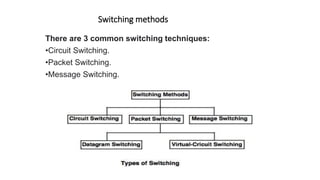
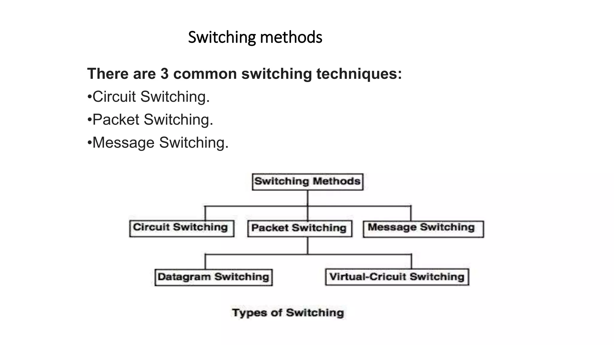
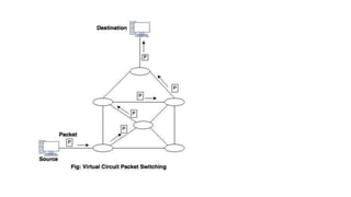
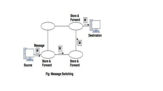
Switching methods
There are 3 common switching techniques:
•Circuit Switching.
•Packet Switching.
•Message Switching.
• Circuit Switching
• Circuit switched network consists of a set of switches connected by physical links.
• In circuit switched network, two nodes communicate with each other over a
dedicated communication path.
• There is a need of pre-specified route from which data will travel and no other
data is permitted.
• Before starting communication, the nodes must make a reservation for the
resources to be used during the communication.
• In this type of switching, once a connection is established, a dedicated path exists
between both ends until the connection is terminated.
•The end systems, such as telephones or
computers are directly connected to a switch.
•When system A needs to communicate with
system B, system A needs to request a
connection to system B that must be accepted by
all switches as well as by B itself.
•This is called as setup phase in which a circuit
is reserved on each link, and the combination of
circuits or channels defines a dedicated path.
•After the establishment of the dedicated circuit,
the data transfer can take place.
•After all data has been transferred, the circuit is
torn down.
• Packet Switching
• In packet switching, messages are divided into packets of fixed or variable size.
• The size of packet is decided by the network and the governing protocol.
• Resource allocation for a packet is not done in packet switching.
• Resources are allocated on demand.
• The resource allocation is done on first-come, first-served basis.
• Each switching node has a small amount of buffer space to hold packets
temporarily.
• If the outgoing line is busy, the packet stays in queue until the line becomes
available.
• Packet switching method uses two routing methods:1.
• Datagram Packet Switching
• Datagram packet switching is normally implemented in the network layer.
• In datagram network, each packet is routed independently through the network.
• Each packet carries a header that contains the full information about the destination.
• When the switch receives the packet, the destination address in the header of the packet is
examined; the routing table is consulted to find the corresponding port through which the packet
should be forwarded.
• 2. Virtual Circuit Packet Switching
• Virtual circuit packet switching is normally done at the data link layer.
• Virtual circuit packet switching establishes a fixed path between a source and a destination
to transfer the packets.
• It is also called as connection oriented network.
• A source and destination have to go through three phases in a virtual circuit packet
switching:
I. Setup phase
ii. Data transfer phase
iii. Connection release phase
A logical connection is established when a sender sends a setup request to the receiver and
the receiver sends back an acknowledgement to the sender if the receiver agree.
• All packets belonging to the same source and destination travel the same path.
• The information is delivered to the receiver in the same order as transmitted by the sender.
• Message Switching
• In message switching, it is not necessary to establish a dedicated path between transmitter and
receiver.
• In this, each message is routed independently through the network.
• Each message carries a header that contains the full information about the destination.
• Each intermediate device receives the whole message and buffers it until there are resources
available to transfer it to the next hop.
• If the next hop does not have enough resources to accommodate large size message, the
message is stored and switch waits.
• For this reason a message switching is sometimes called as Store and Forward Switching.
• Message switching is very slow because of store-and-forward technique.
• Message switching is not recommended for real time applications like voice and video.
•
Switching methods.pptx

Switching methods.pptx

  • 1.
    Switching methods There are3 common switching techniques: •Circuit Switching. •Packet Switching. •Message Switching.
  • 2.
    • Circuit Switching •Circuit switched network consists of a set of switches connected by physical links. • In circuit switched network, two nodes communicate with each other over a dedicated communication path. • There is a need of pre-specified route from which data will travel and no other data is permitted. • Before starting communication, the nodes must make a reservation for the resources to be used during the communication. • In this type of switching, once a connection is established, a dedicated path exists between both ends until the connection is terminated.
  • 3.
    •The end systems,such as telephones or computers are directly connected to a switch. •When system A needs to communicate with system B, system A needs to request a connection to system B that must be accepted by all switches as well as by B itself. •This is called as setup phase in which a circuit is reserved on each link, and the combination of circuits or channels defines a dedicated path. •After the establishment of the dedicated circuit, the data transfer can take place. •After all data has been transferred, the circuit is torn down.
  • 4.
    • Packet Switching •In packet switching, messages are divided into packets of fixed or variable size. • The size of packet is decided by the network and the governing protocol. • Resource allocation for a packet is not done in packet switching. • Resources are allocated on demand. • The resource allocation is done on first-come, first-served basis. • Each switching node has a small amount of buffer space to hold packets temporarily. • If the outgoing line is busy, the packet stays in queue until the line becomes available.
  • 5.
    • Packet switchingmethod uses two routing methods:1. • Datagram Packet Switching • Datagram packet switching is normally implemented in the network layer. • In datagram network, each packet is routed independently through the network. • Each packet carries a header that contains the full information about the destination. • When the switch receives the packet, the destination address in the header of the packet is examined; the routing table is consulted to find the corresponding port through which the packet should be forwarded.
  • 7.
    • 2. VirtualCircuit Packet Switching • Virtual circuit packet switching is normally done at the data link layer. • Virtual circuit packet switching establishes a fixed path between a source and a destination to transfer the packets. • It is also called as connection oriented network. • A source and destination have to go through three phases in a virtual circuit packet switching: I. Setup phase ii. Data transfer phase iii. Connection release phase A logical connection is established when a sender sends a setup request to the receiver and the receiver sends back an acknowledgement to the sender if the receiver agree. • All packets belonging to the same source and destination travel the same path. • The information is delivered to the receiver in the same order as transmitted by the sender.
  • 9.
    • Message Switching •In message switching, it is not necessary to establish a dedicated path between transmitter and receiver. • In this, each message is routed independently through the network. • Each message carries a header that contains the full information about the destination. • Each intermediate device receives the whole message and buffers it until there are resources available to transfer it to the next hop. • If the next hop does not have enough resources to accommodate large size message, the message is stored and switch waits. • For this reason a message switching is sometimes called as Store and Forward Switching. • Message switching is very slow because of store-and-forward technique. • Message switching is not recommended for real time applications like voice and video. •