SlideShare a Scribd company logo
1 of 177
Download to read offline
1
Iron will corrode in dilute nitric acid, but at higher
concentrations the corrosion rate of iron is very little or negligible.
2
 Iron is resistant to corrosion in nitric acid at concentrations around 70%. Faraday
also conformed this by cell made up of passive iron coupled to platinum in concentrated
nitric acid produced little or no current.
 Once passivated under these conditions, it can also exhibit low rates of corrosion as
the nitric acid is diluted.
 However, if this passive film is disturbed, rapid corrosion will begin and re-passivation
will not be possible until the nitric acid concentration is raised to a sufficient level.
Definition 1. A metal or alloy become passive on increasing the electrode potential
towards more noble values (anodic polarization), at which the rate of
 In the Eh – pH diagrams, resistance to metallic corrosion is indicated at stability regions
where either the metal remains thermodynamically stable (immunity) or the metal surface is
covered with an oxide/hydroxide layer (passivity).
 Passivity is due to the formation of thin, impermeable and adherent surface films under
oxidizing conditions (e.g., iron in chromate or nitrite solutions) often associated with anodic
polarization (e.g., iron in H2SO4).
3
towards more noble values (anodic polarization), at which the rate of
anodic dissolution is less than the less noble potential in given
environment.
i.e., noble potential, low corrosion rate
Definition 2. A metal or alloy become passive on increasing the concentration of an
oxidizing agent in an adjacent solution or gas phase in absence of
external current, at which the rate of anodic dissolution is less than
the lower concentration of the oxidizing agent.
 active potential, low corrosion rate
 Examples of metals or alloys (active-passive ) that are passive under Definition 1 are Cr, Ni,
Mo, Ti, Zr, the stainless steel, 70%Ni – 30%Cu alloys (Monel), iron in dissolved chromates
(passive in passivator solutions) and several other metals and alloys.
 Metals and alloys in this category show a marked tendency to polarize anodically and
corrosion potentials of this category approach the OCP of oxygen electrode (exhibit
potentials near those of the noble metals.)
Definition 1 usually conform as well as to Definition 2 based on low corrosion rates.
Definition 1
4
Definition 1 usually conform as well as to Definition 2 based on low corrosion rates.
 Examples of metals that are passive under Definition 2 (passive metals) are Pb immersed in
sulfuric acid, or Mg in water, or iron in inhibited pickling acid or zinc based on lowcorrosion
rates, despite pronounced corrosion tendencies according to thermodynamic data (e.m.f. series).
 Their corrosion potentials are relatively active, and polarization is not pronounced when they
are made the anode of a cell.
Definition 2
Electrochemical basis of active-passive behavior (anodic dissolution
behavior ) of a metal is illustrated in following figure.
5
 As the potential increases towards more noble direction (anodic polarization) than EM/M
+, the
rate of dissolution of the metal also increases. At this point partially insulating films (probably
porous metal sulphate, nitrate or chromate) on metal surface is formed .
 At this point the rate corrosion is maximum and maximum current density is called critical
current density (icritical). The potential corresponding to icritical is called the primary passive
potential (Epp) as it represents the transition of a metal from an active state to a passive state.
 The potential at which the current becomes virtually independent of potential and remains
virtually stationary is called the flade potential (EF). At this point much thinner films (probably
MxOy or Fe (OH)2 or FeO) on metal surface is formed and metal becomes passive.
6
 The minimum current density required to maintain the metal in a passive state is called
passive current density (ip). At ip, the metal dissolution occurs at a constant rate and the oxide
film begins to thicken. The dissolution rate in the passive region, therefore, remains constant.
 On further increase in potential leads to an accelerated rate of corrosion due the breakdown
of passive films and is called transpassive potential (Etranspassive). Now the corrosion product is
Fe3+ and O2 evolution, which causes a sharp increase in the current.
The transpassive potential corresponding to the end of passive region, which corresponds to
the initial point of anodic evolution of oxygen . This may correspond either to the breakdown
(electrolysis) voltage of water, or, to the pitting potential.
Stability of passivity is related to EF. The lower the Eo
F, the easier it
becomes for passivation and higher the film stability. For Cr – Fe alloys, the
value ranges from 0.63 V to -0.10V with 25% chromium addition.
The passive films maybe as thin as 2-10 nm, and they offer a limited
electronic conductivity, and behave like semi-conductors with metallic
properties rather than the properties shown by bulk oxides.
7
In a variety of Fe-Cr alloys, Epp and icritical substantially reduced than iron
because of the formation of uniform protective films.
8
The transpassive region increase with increasing chromium content. As the
film dissolves, cation vacancies are created in the oxide surface and the
conductivity of the film is increased.
 Metals, like Fe, Cr, Ni and Ti, show a strong active-passive behavior. The, cathodic reaction is
a deciding factor in the establishment of passivity. The rate of corrosion depends upon the
degree of polarization of the anode.
 A metal not showing any passivity will exhibit a linear E vs log i relationship. On the other
hand, a metal exhibiting passivity would exhibit a non-linear anodic polarization.
9
hand, a metal exhibiting passivity would exhibit a non-linear anodic polarization.
 Metals, like zinc, magnesium and aluminum, show a passive behavior in atmospheric corrosion.
The rate of corrosion depends on the degree of polarization of both the anode and the cathode.
Parameters Definitions of Parameters
Equilibrium potential
(Eeq or Eo or EM/Mz+)
The potential of an electrode in an electrolyte at which rate of
forward reaction is balanced by the rate of reverse reaction. At
equilibrium potential, the rates of the anodic (oxidation) and
cathodic (reduction) processes are equal, and there is no net
charge transfer.
10
charge transfer.
Passive potential
(Epassive)
The potential at which a metal surface changes from an active to a
passive state. Passive potential is defined as the potential below
which the metal surface remains active and above which the metal
surface remains passive.
Flade potential (EF). The potential at which a metal changes from a passive state to an
active state. Flade potential is defined as the potential below
which the metal surface remains passive and above which the
metal surface remains active.
Transpassive potential
(Etranspassive)
The potential corresponding to the end of passive region
which corresponds to the initial point of anodic evolution
of oxygen. This may correspond either to the breakdown
(electrolysis) voltage of water, or, to the pitting
potential.
Pitting potential (Ep). It is the potential at which there is a sudden increase in
the current density due to breakdown of passive film on
the metal surface in the anodic region.
11
Critical current density
(icritical)
The maximum current density observed in the active
region for a metal or alloy that exhibits an active-passive
behavior.
Passive current density
(ip)
The minimum current density required to maintain the
thickness of the film in the passive range.
 The stainless steel (SS) 316 with 2% Mo is a better material for seawater service than
SS 304 without molybdenum.
 Brass, bronze and copper based alloys are highly desirable for salt water transportation,
The development of alloys for controlling corrosion in specific aggressive
environments is certainly one of the great metallurgical developments of the
twentieth century. Iron - base alloys containing a minimum of 12 wt.% Cr are
known as the stainless steels, they remain bright and tarnish - free for
years, in contrast to iron .
12
 Brass, bronze and copper based alloys are highly desirable for salt water transportation,
however, they are vulnerable for an environment containing ammonia frequently encountered
in agriculture.
 Small alloying additions of copper, chromium, or nickel minimizes the atmospheric
corrosion.
1) The alloying element may reduce either icritical (e.g., chromium alloyed with iron), or ipassive
(e.g., nickel alloyed with copper)].
For the development of corrosion-resistant alloys through passivity
criterion, two approaches can be possible.
13
Elements, like chromium and nickel, which have a lower icritical and ipassive
than iron, reduce the icritical of iron
*Chromium-platinum alloys have a
low resistance to corrosion in
oxidizing acids and a high
resistance in non-oxidizing acid.
14
An increasing chromium content reduces i critical; on the other hand,
decreasing pH and increasing temperature increase i critical.
*In highly oxidizing conditions
the corrosion potential of
chromium is very near the
transpassive region.
15
An increasing Ni content reduces both icritical and ipassive.
2) Alloying with noble metals having high exchange currents densities stimulates the
cathodic reaction and there by increasing the anodic current density (only active EPP metals
such as Ti and Cr) to the critical value for passivation with out any oxidizer.
16
If platinum is added to titanium, the rate of corrosion of titanium is not increased
because, unlike chromium, titanium does not exhibit a transpassive region.
Impact of various cathodic reactions on the corrosion current:
17
Spontaneous passivation of titanium by galvanically coupling to platinum.
18
NOTE: Raises the possibility of anodic protection.
If passivating potential (flade potential > EH2/H+) corrosion rate increases
19
Passivating potential too noble for couple to passivate metal. If very large Pt
cathode coupled, corrosion can be increased to P.
1. Effect of deaeration, aeration, and stirring (velocity) on corrosion of
active-passive stainless steel in neutral saltwater.
20
For an active-passive metal exposed to a diffusion controlled cathodic reaction,
the corrosion rate will increase upto certain velocity levels, beyond which the
corrosion rate decreases rapidly to a very low value on the onset of passivity
and would remain at passive state for still higher velocities.
2. Effect of chloride ions and temperature:
21
 Chloride ions break down the passivity and increase the rate of anodic dissolution.
Breakdown of passivity by chloride ions is local and leads to pitting corrosion.
 An increase in temperature generally decreases the passive range (decreases polarization)
and increases the critical current density (icritical)
3. Effect of oxidizer (Fe2+ or CrO4
2-) concentration:
Fe
2+
or
CrO
4
2-
22
 Corrosion rate of an active-passive alloy initially increases with oxidizer concentration
(while in its active state).
 As soon as passive state is reached, the corrosion rate steeply decreases to a very
low value and remains at this low corrosion passive level.
This region is called region of ‘borderline passivity’ in which any surface disturbance
(scratching) will destabilize passivity, leading to increase in corrosion rate.
 With still further increase in oxidizer concentration, corrosion rate further
increases due to transpassive behavior.
Fe
 Corrosion rate is proportional to anodic current density in the
active state irrespective of whether the alloy is passive type or not.
 Rate of cathodic reduction must exceed icrit to ensure lower corrosion
rates in diffusion controlled process.
Avoid breakdown of passive films in oxidizing environments due to
transpassivity.
 Avoided Border line passivity and stable passive state in oxidizing
conditions is essential.
23
 If the cathodic reduction is activation controlled, a metal
or alloy with an more active Epp is will passivate faster.
 If the cathodic reduction process is diffusion
controlled, a metal or alloy having a small icrit will passivate
faster.
1. Oxide film theory
 The oxide theory attributes corrosion resistance of passive metals and alloys
due to the formation of a protective film on the metal surface.
 There is a formation of a primary layer of lower conductivity and high
porosity partially protective film on the metal surface in the beginning of passivity.
As the current increases in the pores, passive layer is formed at a potential closer
to the Flade potential.
24
 A stable passive film is free from porosity and presents a protective barrier
between the metal and the corrosive environment.
2. Adsorption theory
 The adsorption theory is based on chemisorbed films. Oxygen adsorption
on surfaces can reduce corrosion activity.
 Uhlig in 1946 observed Flade potential of passive iron is too noble by about
0.6V due to adsorbed oxygen atoms on its surface.
Adsorbed oxygen atoms significantly decrease the exchange current density,
thus increasing anodic polarization, favorable for passivation.
 Only potentiostatic approach allows a detailed study of the important parameters
influencing passivity.
 Galvanostatic methods are not adequate for establishing the active-passive behavior.
Above icrit, the curve no longer follows the anodic curve in the passive region;
suddenly jumping into the transpassive region with oxygen evolution in galvanostatic methods.
25
26
27
28
29
30
Show that when applied current density approaches the limiting current
density the over potential at the cathode increases rapidly where as over
potentialat the anode remains very small.
1
Illustration of hydrogen diffusion:
Hydrogen attack is a form of corrosion damage that occurs in carbon
and low-alloy steels exposed to high-pressure gas at high temperatures for
extended periods of time. The increased concentration of surface hydrogen
favors the entrance of hydrogen atoms into the metal lattice, causing
hydrogen embrittlement (loss of ductility). Some times the molecular gases
(H2, CH4, NH3) produced does not dissolve in the lattice, and internal gas
pressures lead to the formation of cracks or fissures in some stressed high -
strength ferrous alloys, called hydrogen cracking or hydrogen blistering.
2
Illustration of hydrogen diffusion:
Causes of hydrogen attack:
 During plating operations
 Pickling in sulfuric acid or hydrochloric acid after electroplating
 The presence sulfur or arsenic compounds in acids favor entrance of
hydrogen into the metal lattice leading to intensified cracking.
 In cleaning of high strength steels in chloride or fluoride solution.
 Manufacturing and fabrication processes.
3
Examples of hydrogen attack:
 Decarburization in nickel alloys during heat treatment at 2012°F (1100°C) in
hydrogen atmospheres.
 The formation of steam in welded steels, copper, nickel, and silver by
reacting with oxygen.
 Formation of ammonia in molybdenum by reaction with nitrogen.
 The disintegration of oxygen-containing copper in the presence of hydrogen.
1. Formation of hydrogen atoms at the steel surface and adsorption on the surface.
2. Diffusion of hydrogen atoms into the steel substrate.
3. Accumulation of hydrogen atoms at hydrogen traps, such as voids around inclusions
in the steel matrix, leading to increased internal pressure, crack initiation and
propagation, and linkage of separate cracks.
Example 1: Cracks or blistering formation in the presence of hydrogen sulfide
4
 Accumulation of hydrogen inside builds up high internal pressure inside the steels and
creates fissures or cracks preferentially at the grain boundary or non-metallic inclusions.
Example 2: Decarburization (High temperature hydrogen attack)
At temperatures above 230°C and hydrogen partial pressure above 100psi (7kg/cm2), atomic
hydrogen reacts with the carbon component in the steel to form methane.
 Accumulation of methane inside builds up high internal pressure inside the steels and creates
fissures preferentially at the grain boundary or non-metallic inclusions.
 Since neither molecular hydrogen or methane is not capable of diffusion through the steel
5
 Since neither molecular hydrogen or methane is not capable of diffusion through the steel
lattice, so these gases accumulate in the steel matrix.
1. Hydrogen embrittlement
2. Hydrogen blistering (Hydrogen induced cracking)
3. High temperature hydrogen attack (hydrogen damage)
The loss of ductility due to the entrance of hydrogen atoms into the
metal lattice is called hydrogen embrittlement.
6
Difference between SCC and hydrogen embrittlement:
 SCC begins at the surface, whereas hydrogen embrittlement begins
internally.
 The magnitude of corrosion is higher at the origin of SCC than observed
with hydrogen embrittlement.
In SCC a specimen becomes more anodic and cracking is accelerated on
applying a current.
7
applying a current.
 In hydrogen embrittlement a specimen becomes more anodic and cracking
is accelerated on applying a current.
Prevention of hydrogen embrittlement:
1. Proper plating and pickling conditions and coatings:
1. Avoid Chlorides and fluorides in plating and pickling baths.
2. Provide low temperature aging 160oC—370oC for long time after plating.
3. Very-high-strength steels should not be subjected to cadmium plating
or hot dip galvanizing.
4. Hydrogen embrittlement of titanium can be avoided if the ratio of
HNO3/HF exceeds 10.
8
1. The removal of hydrogen in steels can be carried out by heat treatment at
temperatures up to 392°F (200°C) after plating, a process known as baking.
2. Hydrogen can be removed from titanium, zirconium, and their alloys by
annealing in vacuum.
2. Heat treatment:
3. Alloying additions:
1. Alloys with nickel or molybdenum (< 0.75%) or vanadium reduce susceptibility
2. Carbon content should be kept low.
3. Add inhibitors to pickling baths to minimize hydrogen embrittlement.
4.The embrittlement of steel in gaseous environments can be inhibited by adding 0.4 to 0.7
vol.% oxygen
5. Use low hydrogen welding rods.
9
A crack or fissures in some stressed high - strength ferrous alloys
due to the formation of hydrogen molecules into the metal matrix is called
hydrogen blistering or hydrogen induced cracking.
10
 Accumulation of hydrogen inside builds up high internal pressure inside the steels and
creates fissures or cracks preferentially at the grain boundary or non-metallic inclusions.
Hydrogen induced cracking:
11
Blister formation:
12
Hydrogen blistering in the wall of a container:
13
Prevention of hydrogen blistering or crack:
1. The decreased solubility of hydrogen in bcc structural steel compared to the
fcc structure steel
2. A reduced cooling rate inhibits the formation of martensite and also allows
hydrogen to be slowly released from the steel, there by eliminating the damage.
3. Hot-rolled steel or annealed steel is preferable to cold-rolled steel.
4. The use of low-sulfur, calcium-treated, or argon-blown steels is recommended.
1. Heat treatment:
14
4. The use of low-sulfur, calcium-treated, or argon-blown steels is recommended.
2. Alloying additions:
1. Using steel resistance to hydrogen induces cracking, such as steels containing
Cu or cobalt. Carbon content should be kept low.
2. Treatment with synthetic slag (calcium aluminate, calcium silicate and calcium
fluoride) or the addition of rare earth metals can favor the formation of less
detrimental globular sulfides.
3. Inhibitors can minimize the hydrogen blistering because the cathodic reduction
of hydrogen ions is also retarded.
4.The Coating or lining. A rubber lining on steel, or the cladding of steel with
austenitic stainless steel or nickel can minimize the hydrogen blistering.
5. The incidence of hydrogen blistering can be greatly reduced by removing
such hydrogen evolution poisons as sulfides, arsenic compounds, and phosphorus-
containing ions from the environment.
15
A crack or fissures in some stressed high - strength ferrous alloys
due to the formation of other than hydrogen molecules like methane or
ammonia into the metal matrix is called high temperature hydrogen attack
(hydrogen damage)
MCQ 1:
16
17
1
Almost all metals, alloys and materials of technological interest will oxidize and
corrode at high temperatures, leading to scaling, loss of material and changes
in physical properties. This is sometimes called “ dry ” corrosion, in contrast
to “ wet ” corrosion.
 Gaseous attack is not limited to oxygen however, with sulphur-bearing gases, carbon oxides,
nitrous oxides and halogens attacking materials in a different manner.
 Furthermore, high temperature corrosion is not restricted to the gaseous phase – solid ash
2
 Furthermore, high temperature corrosion is not restricted to the gaseous phase – solid ash
and salt deposits contribute to the corrosive effect.
 In the liquid phase, molten metals and molten salts pose their own unique variety of
challenges
 Usually ions, rather than atoms, migrate through solid oxides, sulfides, or halides. The
migrating ions are not hydrated, and they diffuse simultaneously with electrons.
 For copper oxidizing in O2, or silver tarnishing in a contaminated atmosphere, the solid
electrolytes are Cu2O and Ag2S, respectively.
Present trend in most high - temperature processes industries is to increase the
operating temperatures in order to obtain to increased efficiency, but also to reduce
emissions, thereby helping to achieve sustainability and improving economics.
 For example, partially insulating the combustion chamber on a Diesel engine increased
the piston surface temperature from 450° C to 900° C, and it also increased the
combustion efficiency (decreased fuel consumption) by 20% and reduced the nonburned
hydrocarbons emission .
So, high temperature corrosion is a widespread problem in various industries
such as:
3
such as:
Power generation (nuclear and fossil fuel)
Heat treating, Refining and petrochemical
Mineral and metallurgical processing
Chemical processing, pulp and paper
Refining and petrochemical
Automotive and waste incineration
An oxidation reaction between a metal (M) and the oxygen gas (O2) can be
written as
Thermodynamically, an oxide will form on the surface of a metal when the
oxygen potential in the environment is greater than the oxygen partial
pressure (dissociation pressure ofthe oxide) in equilibrium with the oxide.
4
A graphical representations of standard free energies for the formation of
oxides as a function of temperature are known as Ellingham/Richardson
diagrams. The partial pressure of oxygen required for oxidation at various
temperatures can be read from the nomographic scale given on the right side
of the plot.
 The strong oxide former is shown at the bottom (more negative value of ΔGO ) of the
plot, while the weakest oxide forming metal is shown on the upper part of the curve.
 Ores can be reduced by carbon only if its ∆Go is above that one of the carbon oxidation
reaction. Practical refining temperature are generally limited to about 1500o K.
5
reaction. Practical refining temperature are generally limited to about 1500o K.
 A given metal can reduce the oxides of other metals whose lines lie above theirs on the
diagram. so magnesium can reduce titanium oxide to metallic titanium (or Cr or Ni or Zn).
 Used to determine the ratio of carbon monoxide to carbon dioxide (PCO/PCO2) that will
be able to reduce the oxide to metal at a given temperature.
 The harder the oxide is to reduce, the greater the proportion of CO needed in the
gases.
6
7
8
Pilling-Bedworth ratio describes the type of oxide film that forms on a metal
surface during oxidation. Three types of oxides may form, depending on the
volume ratio between the metal and the oxide.
 (a) magnesium produces a porous
oxide film.
9
 (b) aluminum forms a protective,
adherent, nonporous oxide film,
and
 (c) iron forms an oxide film that
spills off the surface and provides
poor protection.
The Pilling Bedworth ratio (PBR) is defined as the ratio of the molar volume of
metal to the molar volume of the oxide formed on it. It says whether the
volume of reaction product is greater or less than the volume of metal from
which the product forms.
10
A0 Molecular (or formula) weight of the oxide
AM Atomic weight of the metal
ρM Metal density
ρ0 Oxide density
PBR  1 -a protective scale is predicted to form (Al2O3,NiO,SiO2, CrO2)
-compressive stresses in oxide film → the scale remains adherent to the
substrate metal and uniformly cover metal surface
PBR  1 -the scale is formed in tension and tends to be non-protective (MgO, CaO,
Li2O, FeO, Cu2O)
-tensile stresses in oxide film → brittle oxide cracks
-alkali metals have a violent reaction when exposed to air
PBR  1 -more thick scales are non-protective (TiO2, WO3)
11
PBR  1
The Pilling - Bedworth ratios for some metals are listed in following table. As
shown, this ratio does not accurately predict oxidation resistance, although
there is some qualitative agreement.
12
In addition to the Pilling – Bedworth ratio,
protection by an oxide depends on good
adherence of the oxide to the substrate, low
vapor pressure and high melting temperature of
the oxide, slow oxide growth rate, high
thermodynamic stability, and low electrical
conductivity or low diffusion coefficients for
metal ions and oxygen.
The density of aluminum is 2.7 g/cm3 and that of Al2O3 is about 4 g/cm3.
Describe the characteristics of the aluminum-oxide film. Compare with
the oxide film that forms on tungsten. The density of tungsten is 19.254
g/cm3 and that of WO3 is 7.3 g/cm3.
Example 1:
Solutions:
13
Since P-B ~ 1 for aluminum, the Al2O3 film is nonporous and adherent, providing
protection to the underlying aluminum.
 However, P-B  2 for tungsten, so the WO should be non-adherent and non-
14
 However, P-B  2 for tungsten, so the WO3 should be non-adherent and non-
protective.
The three main equations that express weight gain per unit area or thickness
(W) of film or scale forming on any metal within time (t) are (1) the linear, (2)
the parabolic, and (3) the logarithmic. The k represents corresponding rate
constant.
1. Linear equation:  The rate of oxidation remains constant with time (or
dy/dt = kL= slope) and is independent of the amount of gas
or metal previously consumed in the reaction.
Such reactions usually take place by surface or phase
15
 Such reactions usually take place by surface or phase
boundary reactions.
 Alkali metals and alkaline earth metals oxidize linearly and
have oxide to metal volume ratio less than 1.
 The linear rate law is usually followed when a protective
scale cracks or spalls (WO3 or MoO3), leading to direct
access of gas to metal.
Other examples: Tantalum and columbium (niobium)
2. Parabolic equation:
 The parabolic rate law assumes that the
diffusion of metal cations or oxygen anions or
migration of electrons through the scale is
the rate controlling step and is derived from
Ex: Fe, Co, Ni and Cu
16
the rate controlling step and is derived from
Fick's first law of diffusion. It is an inversely
proportional to scale thickness.
 Most metals and engineering alloys follow
parabolic kinetics at elevated temperatures
and have oxide to metal volume ratio 1-2,
which is protective in nature. The parabolic
law was first derived by Wagner, assuming
diffusion of charged species through the
oxide layer.
3. Logarithmic behavior:
The rate of reaction rises very fast in the
beginning and then slows down, either following a
direct or inverse logarithmic law. It is generally
observed with thin oxide layers ( 1000 Å) at low
Ex: Al, Cu and Fe
17
observed with thin oxide layers ( 1000 Å) at low
temperatures or slightly elevated temperatures of
metals like Al, Cu and Fe.
 It is often difficult to distinguish between the
logarithmic and the inverse logarithmic equations.
These are based on the transport of either ions or
electrons (electrical potential gradent) through thin
oxide layers.
Ex: Zirconium and hafnium
18
19
20
MCQ 1:
21
MCQ 2:
MCQ 3:
MCQ 4:
22
MCQ 5:
MCQ 6:
23
MCQ 7:
MCQ 8:
24
MCQ 8:
MCQ 9:
MCQ 10:
25
MCQ 10:
MCQ 11:
MCQ 12:
26
MCQ 12:
27
1
Anodization involves thickening of oxide layers on metals
such as Al, Mg, Ti, and their alloys through application of a
voltage or current (100 or more A/m2) to a metal surface
that is immersed in a suitable electrolyte.
2
Anodizing developed around 1917 with first US patent in 1925
The oxide so formed must be hydrated to improve its
protective qualities by exposing anodized articles to steam
or hot water for several minutes, a process called sealing.
Cathode Rn.:
Anode Rn.:
Total Rn.:
The hydrogen ions moving to the cathode where they are reduced to
3
 The anodic films formed can be either porous or nonporous, depending on which
electrolyte is used.
 Sulfuric, chromic, phosphoric and oxalic acid electrolytes form both barrier and
porous layers while boric acid electrolytes produce only barrier films.
 Sulfuric acid is the most widely used electrolyte. To obtain the maximum corrosion
resistance, the porous coating must be sealed after dying.
The hydrogen ions moving to the cathode where they are reduced to
hydrogen gas. At the anode surface they react with the
oxide/hydroxide ions to form aluminum oxide.
4
Porous-type coatings exhibit a duplex structure consisting
of an inner barrier layer and a crystalline outer layer that
consists of a regularly spaced array of pores in certain
cases.
5
As with barrier film formation, Al3+cation and O2- and OH-
anion transport occurs during anodization, but in this case
Al3+ is ejected into solution instead of participating in film
formation. The Al3+ then reprecipitates on the previously
existing barrier layer leading to the formation of a porous
outer layer.
6
Bright anodizing :
 Bright anodizing is a special type of anodizing(in combination
with polishing) when glossy or shiny surfaces are required.
 Finishing trim components, automotive applications like
window trims and bumpers.
Hard anodizing :
 Hard anodizing is a term used to describe the production
of anodic coatings with film hardness (350-1400 HV) or
abrasion resistance as their primary characteristic.
7
abrasion resistance as their primary characteristic.
 Hard anodized aluminum shows a good heat resistance,
and a hard anodic oxide coating of 75µm withstands short
exposures to temperatures oft he order of 2000 0C.
 In industry for components which require a very wear
resistant surface such as pistons, cylinders, and hydraulic
gear.
8
9
10
11
TiO2 films have attracted attention for a great variety of applications such as:
dye-sensitizing solar cells,
photo catalysis,
gas sensing …
TiO2 nanoporous structures are desirible for these applications due to their high
surface area
TiO2 Nanotubes Arrays fabricated by anodizing process
A number of techniques have been used to make TiO2 films, including:
Sol-gel,
Chemical vapor deposition
Pulsed laser deposition
DC Power supply
(+) (-)
e - e -
Electrolyte (HF)
Anode Cathode
Oxide
Electrolyte
Oxide
Ti
4+
O 2-
Ti
H2O
H2O
Ti
TiO2 Nanotubes Arrays fabricated by anodizing process
Ti
Oxide
Ti
4+
Ti
TiO2
Ti 4+
Ti TiO2
Ti
Tubular morphology
TiO2 barrier oxide
Top view Side view
TiO2 Nanotubes Arrays fabricated by anodizing process
Tube wall: ~10 nm
Tube hole diameter: ~100 nm
Tube height : ~ 300 nm
Anodizing Voltage: 20V
Anodizing Time: 20 min
100
nm
10
nm
~300 nm
Morphology
Description
Forming
Conditions
Void volume estimated ~ 77 %
HF Solution
TiO2 Nanotubes Arrays fabricated by anodizing process
2 min 5 min
Tube size with varied anodizing time (10V)
TiO2 Nanotubes Arrays fabricated by anodizing process
10 min 20 min
TiO2 nanotubes formed at 20 V for 20 min in HF solution.
no heat treatment 300 oC, 3h heat treatment 700 oC, 3h heat treatment
TiO2 Nanotubes Arrays fabricated by anodizing process
2 0 3 0 4 0 5 0 6 0 7 0 8 0 9 0
0
1 0 0 0
2 0 0 0
3 0 0 0
4 0 0 0
5 0 0 0
T (2 0 1 )
T (1 0 3 )
T (1 0 2 )
T (0 0 2 )
T (1 0 0 )
T (1 0 1 )
R (1 1 0 )
R (1 0 1 ) R (2 1 1 )
A (1 0 1 )
H T (7 0 0
o
C , 3 h ) N T
H T (3 0 0
o
C , 3 h ) N T
A n o d iz e d (2 0 V ) T iO 2
N T
Intensity
2 
no heat treatment 300 oC, 3h heat treatment 700 oC, 3h heat treatment
General description of TONT
TiO2 Nanotubes Arrays fabricated by anodizing process
100 nm
TiO2 Nanotubes TiO2 Nanotubes coated with Pt or Pd
100 nm
What is Anodic Porous Alumina?
 Aluminum oxide grown on an Al substrate in an electrolytic cell. The resulting
structure consists of an array of tunable nanometer-sized pores surrounded
by an alumina backbone.
Purpose:
 To understand the mechanisms involved in the growth and
ordering of anodic porous alumina.
Motivation:
Why do we want to fabricate nanostructures?
 Interest in using anodic porous alumina as a nano- template to
fabricate nanometer-sized structures (e.g. nanofabrication of
quantum dots).
1. Fundamental physical interest in the nanometer size regime. Properties
of nano-sized structures are different from their bulk and molecular
counterparts.
2. Technological applications as electronic and optical devices.
 Microfiltration.
 Optical waveguides
and photonic crystals
for optical circuits.
Porous Alumina used as
optical waveguide.
H. Masuda, et. al., Jpn. J. Appl.
Phys. 38, L1403 (1999).
Commercially available
Anopore filter.
http://www.2spi.com/catalo
g/spec_prep/filter2.html
1. Physics:
 Explore optical, electrical,
and magnetic quantum
confinement.
2. Engineering:
for optical circuits.
 Template for carbon
nanotube growth for
electronic,
mechanical
applications.
 Ordered arrays of
quantum dots for
lasers,
photodetectors.
 ULSI memory devices
and ICs.
Ordered arrays of carbon
nanotubes fabricated using
a porous alumina template.
J. Li, et al., Appl. Phys. Lett.
75(3), 367 (1999).
Fabrication
 Anodize aluminum in electrolyte
(e.g. Oxalic Acid)
Two main types of anodic oxide films can be grown depending on
the nature of the electrolyte:
1. Barrier-Type Films:
 Grown Oxide Insoluble in Electrolyte
 Nearly Neutral Electrolytes (pH 5-7)
2. Porous-Type Films:
 Grown Oxide Slightly Soluble in Electrolyte
 Aqueous Sulfuric, Oxalic, and Phosphoric Acid
Electrolytes
 Anodize aluminum in electrolyte (e.g. Oxalic Acid).
 Oxide grows at the metal/oxide and oxide/electrolyte
interfaces, pores initiate at random positions by field-
assisted dissolution at the oxide/electrolyte interface.
 Ordering requires appropriate potentials and long
anodization times.
 Ordering results from repulsion between neighboring
pores due to mechanical stress at the metal/oxide
interface.
Apparatus
interface.
H. Masuda and K. Fukuda, Science 268, 1466 (1995).
Resulting Structure
 Oxide growth proceeds via ionic
conduction and reaction of Al
cations and oxygen containing
anions under the influence of an
applied field.
(e.g. 2Al+ + 3OH- 
Al2O3+3H++6e-)
 Pores initiate at random
positions through field-assisted
dissolution of the oxide at the
oxide/electrolyte interface.
V.P. Parkhutik, and V.I. Shershulsky, J. Phys. D:Appl. Phys. 25, 1258
(1992).
oxide/electrolyte interface.
 Initially oxide growth
dominates. (I)
 Dissolution becomes
competitive, barrier layer
thins, and pores initiate. (II)
 Approaches steady state
where both mechanisms
occur at roughly the same
rate. (III and IV)
Ordered Nano-Templates
 Tunable diameters and spacings
from 20 nm to 500 nm.
 Polycrystalline structure: ordered
micron-sized domains, defects at
grain boundaries.
 Low temperature growth produces
unordered 4-10 nm arrays.
Ordered
Oxalic
Near-Ordered
Sulfuric
Ordered Growth of Porous Alumina
 Ordered pore arrays obtained in three
different electrolytes for long
anodization times and appropriate
voltages (specific for each electrolyte).
 Polycrystalline structure with perfectly
ordered domains a few microns in size.
Defects occur at grain boundaries.
 Porous alumina used as an
evaporation mask to grow quantum
dots.
Thermally Evaporated Nano-Dots:
Gold
H. Masuda et al. , Jpn. J. Appl. Phys.
35, L126 (1996).
Overview: Mask Processing
AFM of
Unopened
Barrier Layer
(1 mm x 1 mm)
1.
2.
3.
1. Anodize sample for a
long time to achieve
ordered pores.
2. Chemically remove the
alumina in a mixture of
phosphoric and chromic
acid.
3. Anodize sample for a
short time.
4. Coat top surface of
alumina with a polymer
7. Remove collodion and
place alumina on desired
substrate.
H. Masuda et al. , Jpn. J. Appl. Phys. 35, L126
(1996).
4.
5.
6.
7.
alumina with a polymer
(collodion) to protect it
from further processing.
5. Remove Al Substrate in a
saturated HgCl2 solution.
6. Remove the barrier layer
in 5 wt.% Phosphoric
Acid.
 Apply black wax around the area that you want to anodize.
 Electropolish Aluminum surface to make it smooth.
 Anodize the sample that should be ordered for 15 hours in oxalic acid.
 Anodize the sample that should be disordered for 1 hour in oxalic acid.
 Chemically remove the alumina in a mixture of phosphoric and
chromic acid.
 Anodize both samples for one hour in oxalic acid.
 Coat top surface of alumina with a polymer (collodion) to protect it
from further processing.
 Remove Al substrate in a saturated HgCl2 solution.
 Use a piece of silicon to pick up oxide and polymer and move to 5 wt. %
phosphoric acid. This removes barrier layer.
 Remove collodion and place alumina on desired substrate- silicon for
SEM characterization and quartz for UV-Vis characterization.
Ordered AAO (100k magnification) Unordered AAO (100k magnification)
Ordered Au dots (100k magnification) Unordered Au dots (100k magnification)
1
The term “conversion coating” is used to describe coatings in which
the substrate metal provides ions that become part of the protective
coating due to the reaction of the metal surface with a chemical medium.
Conversion coating has a dimensional growth and final product have
greater volume than the original metal. The coating layers are
composed of inorganic compounds that are chemically inert.
The corrosion products thus formed build a barrier protection
for the substrate metal. This barrier reduces the active surface
2
for the substrate metal. This barrier reduces the active surface
area on the base metal, thereby delaying the transport of oxidizers
and aggressive species. By so doing, the coating inhibits the
formation of corrosion cells.
 To improve the adherence of the organic layers by the formation of a
uniform corrosion product layer
 To provide a uniform, grease-free surface and electrically insulating barrier
layers with high surface tension
 removal of contaminants (oils, fats, particles)
To provide active corrosion inhibition by reducing the rate of the
oxygen reduction reaction, or by passivating the metallic substrate
Conversion layers are used for various reasons, including:
3
oxygen reduction reaction, or by passivating the metallic substrate
 Secondary barrier action of corrosion products
Conversion coatings belonging in this group are
phosphate, chromate, oxide, and anodized coatings.
These coatings are composed of corrosion products
that have been formed artificially by chemical or
electrochemical reactions in selected solutions.
Phosphate coating transforms the base metal surface
(e.g., iron, steel, zinc, aluminum, and their alloys.) into
phosphate layers by treating with a weak phosphoric acid
solution of iron, zinc, or manganese phosphate.
 Phosphate films are formed by the dissolution of base metal and the precipitation of
phosphate films.
 The metal surface must be free of greases, oils, and other carbonaceous materials
4
 The metal surface must be free of greases, oils, and other carbonaceous materials
before immersion in the phosphating solution or before spray application.
 Baths operating at 120°F (50°C) have pH values of approximately 2 while those
operating below 120°F (50°C) have pH values of approximately 3.
The zinc phosphate coating is basically the result of a corrosion process. Reactions
of iron and steel in a zinc phosphate solution are as follows:
5
With these reactions, the phosphate film consists of
phosphophyllite and Hopeite.
6
7
Applications:
 Phosphating increases the uniformity in the surface texture and surface
area, which improves paint adhesion, and in turn increases the service life of
a paint film. -----------Useful preparation for painting of automobiles
 They are porous and so make an attractive base for application of paints
and organic coatings.
 Phosphate solubility's are lowest in the pH range of 6 to 8. They are
stable in neutral environments and are non-electric conductive compounds.
8
stable in neutral environments and are non-electric conductive compounds.
Limitations :
 Phosphate film deposits on cathodic areas and anodic sites remain in
the form of pinholes. Consequently, the continuity of phosphate films is not
as good as those of anodic oxide and chromate films.
 Alkaline residues on the surface of the base metal lead to under film
corrosion.
9
10
Chromate coating transforms the base metal surface (e.g.,
Al and its alloys, Mg, Zn, and Cd) into amorphous gel-
like continuous layer consisting of insoluble chromium
compounds and soluble hexavalent chromium compounds by
treating with a source of hexavalent chromium ion (e.g.,
chromate, dichromate, or chromic acid) and an acid.
 The coating structure provides a secondary barrier, inhibiting action, and also good
11
 The coating structure provides a secondary barrier, inhibiting action, and also good
adhesion for lacquer films.
Chromate coatings provide their corrosion resistance based on the following three
properties:
Chrome baths always contain a source of hexavalent chromium ion
(e.g., chromate, dichromate, or chromic acid) and an acid to produce a
12
(e.g., chromate, dichromate, or chromic acid) and an acid to produce a
low pH, which is usually in the range of 0 to 3. During the
reaction, hexavalent chromium is partially reduced to trivalent
chromium, forming a complex mixture consisting largely of hydrated
hydroxides of both chromium and aluminum:
Chromic acid processes:
There are two types of processes by which conversion coatings can be produced:
chromic acid processes and chromic-phosphoric acid processes.
 This conversion coating is yellow to brown in
color and consists primarily of oxide Cr2O3, better
described as an amorphous hydroxide Cr(OH)3.
13
Chromic-phosphoric acid processes:
described as an amorphous hydroxide Cr(OH)3.
 This conversion coating is greenish in color and
consists primarily of hydrated chromium phosphate with
hydrated chromium oxide concentrated toward the metal.
Applications:
 Chromium conversion coatings can be used as a base for paints or alone for
corrosion protection.
 Previously it was described how the leached hexavalent chromium acts as an
anodic inhibitor by forming passive films over defects in the coating.
Limitations :
14
 The longer the time of wetness or direct atmosphere, the shorter the service
life of the coating because chromate coatings absorb moisture and moisture results
in the leaching of hexavalent chromium.
 A source of fluoride ions is also usually present. These fluoride ions will
attack the original (natural) aluminum oxide film, and also fluoride ions prevents the
aluminum ions (from base substrate) from precipitating by forming complex ions.
 Because the films formed on Al by the chromic acid-phosphoric acid process contain
no hexavalent chromium, they do not provide self-healing from defects.
 Iron or steel articles to be coated are heated in a closed retort to a temperature of
1600°F (871°C), after which superheated steam is admitted.
 This results in the formation of red oxide (FeO) and magnetic oxide (Fe3O4).
 Carbon monoxide is then admitted to the retort, reducing the red oxide to magnetic
oxide, which is resistant to corrosion. Each operation takes approximately 20 min
Such coatings, blue, brown, or black in color, consist mostly of Fe3O4 and, phosphate
coatings, are not protective against corrosion.
15
Iron and steel may also be coated by electrolytic means. The article to be
coated is made the anode in an alkaline solution (anodic oxidation). These
coatings are primarily for appearance, such as for cast iron stove parts.
1
2
 Plasma is an ionized gaseous cloud composed of free electrons, positive
ions, neutral atoms and molecules because of its unique properties.
 Some have referred to it as the fourth state of matter.
 Plasma is generated whenever sufficient energy is imparted to a gas to
cause some of it to ionize.
 State of ionized gas (plasma) is possible when the mean kinetic energy
of plasma particles is of the order of magnitude of the ionization
energy
Plasma :
3
plasma spraying, a thermal spray process in which a non-transferred
arc is a source of heat that ionizes a gas which melts the coating material and
deposit it on to the work piece.
Plasma spray deposition is a process that combines particle melting, quenching
and consolidation in a single operation.
Non transferred arc plasma gun Schematic
4
1. When the plasma jet is formed, a powder through nozzles carried by
the carrier gas is injected into it.
2. Accelerated and melted powder particles leave the plasma jet in the
form of molten particle stream.
3. The molten particles bombard the substrate surface deposited on the
surface.
4. Then they cool and forming a coating.
5. Every molten particle has a high thrust which leads to high bond
strength of the coat.
6. The temperature of the substrate remains below 100 ˚C.
7. Thickness of the coat varies between 0.3 and 1 mm, but it may be also
up to 5 mm
Plasma spraying process
5
8. The temperature at the core of the plasma jet is 10,000-15,000 K.
9. Metal or ceramic particles injected into the plasma undergo rapid melting
and at the same time are accelerated.
10. These molten droplets moving at high velocities, exceeding 100 m/s,
impact on the surfaces of the substrate forming adherent coating.
11. The coating is incrementally built up by the impact of successive particles
by the process of flattening, cooling and solidification.
12. By virtue of the high cooling rates, typically 105 to 106 K/sec., the
resulting microstructures are fine-grained and homogeneous
 The plasma spray process is mostly used in normal atmospheric conditions
(air or atmospheric plasma spray - APS).
 It also has the ability to operate in an inert atmosphere using method of
Low Pressure Plasma Spraying (LPPS) or Vacuum Plasma Spraying (VPS).
 This enables deposition of materials sensitive to oxidation (Ti, Mg).
6
Plasma spray process
7
 Plasma sprayed coatings are extensively used for high temperature
chemical barrier applications.
 Plasma spraying is used for both metallic and non-metallic materials usually
more suitable for high melting point materials like refractory materials and
cremets.
 Temperature in the plasma arc can be as high as 2,000°C to 20,000°C and
is capable of melting anything.
Requirements for the plasma spraying
 Roughness of the substrate surface
 Cleanliness of the substrate surfaces
 Bond coat
 Cooling water
8
Process parameters for the plasma spraying
 Arc power
 Plasma gas
 Carrier gas
 Mass flow rate of powder
 Powder related variables(size,MP etc.,)
 Stand-0ff-distance (Spray Distance)
 Spraying angle
 Substrate cooling
 Angle of powder injection
9
Industrial applications of the plasma spraying
 Steel industry
 Aircraft industry
 Paper industry
 Gas turbine industry
 Glass industry
 Automotive industry and production of combustion engines
 Medical industry
 Chemical plants
 Foundry mills
 Textile industry
10
Advantages of Plasma spraying
1. Very flexible in coating material selection and optimization for specific
resistance to corrosive environments and particle abrasion/erosion.
2. Unique alloys and microstructures can be obtained with thermal spraying
which are not possible with a wrought material.
3. Costs of the coating solution are normally significantly lower than those
of a highly alloyed bulk material.
4. Forms microstructure with fine, equiaxed grains and without columnar
boundaries.
5. Produces deposits that do not change in composition with thickness
(length of deposition time).
6. Can change from depositing a metal to a continuously varying mixture of
metals ceramics (i.e. functionally graded materials).
11
7. High deposition rates (4kg/h).
8. Fabricates freestanding forms of virtually any material or any materials
combination.
9. Process materials in virtually any environment e.g. air, reduced pressure
inert gas, high pressure etc.
1
2
Sputter deposition:
When a solid surface is bombarded with energetic ions, surface atoms of the
solid are scattered backward due to collisions between the surface atoms and
the energetic particles. The phenomenon is called “back-sputtering” or simply
“sputtering
Several types of sputtering systems are used in practice including
DC diode, RF-diode, magnetron diode, and ion beam sputtering.
3
 Operation pressure (~1-100mTorr)
 Power (few 100W)
 For DC sputtering, voltage -2 to -5kV.
 Additional substrate bias voltage.
 Substrate temperature (20-700oC)
Major sputtering process parameters:
Sputtering process can be run in DC or RF mode
In addition to IC industry, a wide range of industrial products use sputtering:
 LCD
 computer hard drives
 hard coatings for tools
 metals on plastics.
4
Sputter deposition advantages
1. Able to deposit a wide variety of metals, insulators, alloys and
composites.
2. Replication of target composition in the deposited films.
3. Capable of in-situ cleaning prior to film deposition by reversing the
potential on the electrodes .
4. Better film quality and step coverage than evaporation.
5. More reproducible deposition control – same deposition rate for same
process parameters (not true for evaporation), so easy film thickness
control via time.
6. Can use large area targets for uniform thickness over large substrates.
7. Sufficient target material for many depositions.
8. No x-ray damage.
5
Disadvantages:
1. Substrate damage due to ion bombardment or UV generated by plasma.
2. Higher pressures 1 –100 mtorr (  10-5 torr in evaporation), more
contaminations unless using ultra clean gasses and ultra clean targets.
3. Deposition rate of some materials quite low.
4. Some materials (e.g., organics) degrade due to ionic bombardment.
5. Most of the energy incident on the target becomes heat, which must be
removed.
6
Mechanisms of sputtering and alloy sputtering
 The ion impact may set up a series of collisions between atoms of the target, possibly
leading to the ejection of some of these atoms. This ejection process is known as
sputtering.
 Here we are interested in sputter deposition. Of course sputter can also be used as
an etching method (the substrate to be etched will be the ‘target’), which is called
sputter etching.
 Unlike evaporation, composition of alloy in film is approximately the same as target.
 Target NOT melted, slow diffusion (no material flow) mixing.
 When target reaches steady state, surface composition balances sputter yield.
DC plasma
 Plasma is ionized gas, with nearly equal number of ions and electrons, plus
neutrals (un-ionized molecules including those at ground state and excited
state; free radicals such as atomic O, H, F – but no free radicals for Ar
plasma).
 Glow is due to de-excitation of excited Ar. So glow only exists where there
are lots of electrons to excite Ar.
 Cathode glow region: very close to cathode, secondary electrons are
created by Ar bombardment of target material.
 Cathode dark space/sheath: electrons pass too fast with little excitation.
 Anode sheath: electrons lost to anode due to its faster random movement
Sputter yield
The sputter yield S, which is the removal rate of surface atoms due to ion
bombardment, is defined as the mean number of atoms removed from the
surface of a solid per incident ion and is given by
S=Atoms removed/Incident ions
Sputtering is caused by the interactions of incident ions with target
Surface atoms.
• Energy of incident ions
• Target materials
• Incident angles of ions
• Crystal structure of the target surface.
Sputter yield factors
9
1 .Weight loss of target
2. Decrease of target thickness
3. Collection of the sputtered materials
4. Detection of sputtered particles in flight
Sputter yield Measurement methods
RF (Radio frequency ) sputter deposition
1. Good for insulating materials because, positive charge (Ar+) build up on
the cathode (target) in DC sputtering systems. Alternating potential can
avoid charge buildup
2. When frequencies less than 50kHz, both electrons and ions can follow
the switching of the anode and cathode, basically DC sputtering of both
surfaces.
3. When frequencies well above 50kHz, ions (heavy) can no longer follow the
switching, and electrons can neutralize positive charge buildup on each
electrode during each half cycle.
4. As now electrons gain energy directly from RF powder (no need of
secondary electrons to maintain plasma), and oscillating electrons are more
efficient to ionize the gas, RF sputter is capable of running in lower pressure
(1-15 mTorr), so fewer gas collisions and more
line of sight deposition.
11
 For symmetric target-substrate configuration, sputtering of both
surfaces will occur, though in the opposite half cycles.
 When the electrode areas are not equal, the field must be higher at the
smaller electrode (higher current density), to maintain overall current
continuity.
 It was found that voltage drop across the dark sheath of the two
electrodes satisfy the relation: (A is the area of the electrode)
 Thus by making the target electrode much smaller, sputtering occurs
only on the target. Wafer electrode can also be connected to chamber
walls, further increasing V2/V1.
RF Plasma

V1
V2

A2
A1






m
12
Chemical Vapor Deposition (CVD)
SHRIDEVI S BHAT
06/09/2013
Introduction
• CVD is a chemical process used to produce high-purity,
high-performance solid materials.
• This technique is suitable for the manufacture of
coatings, powders, fibers and monolithic components.
• This technique is often used in many thin film
applications.
• By varying the experimental conditions—substrate
material, substrate temperature, composition of the
reaction gas mixture, total pressure gas flows, etc.—
materials with different properties can be grown.
Definition and Types
Chemical vapour deposition may be defined as the deposition of a solid on a
heated surface from a chemical reaction in the vapour phase. It belongs to the
class of vapour-transfer processes which is atomistic in nature, that is the
deposition species are atoms or molecules or a combination of these.
Schematic of a simple thermal CVD reactor
Sequence of events during deposition
Classified by operating pressure:
 Atmospheric pressure CVD (APCVD) – CVD at atmospheric pressure.
 Low-pressure CVD (LPCVD) – CVD at sub-atmospheric pressures.
 Ultrahigh vacuum CVD (UHVCVD) – CVD at very low pressure, below 10−6
Pa (~10−8 torr).
Classified by physical characteristics of vapour:
 Aerosol assisted CVD (AACVD) – CVD in which the precursors are transported to
the substrate by means of a liquid/gas aerosol, which can be generated
ultrasonically.
 Direct liquid injection CVD (DLICVD) – CVD in which the precursors are in liquid
form (liquid or solid dissolved in a convenient solvent). Liquid solutions are
injected in a vaporization chamber towards injectors. The precursor vapours are
then transported to the substrate as in classical CVD.
Plasma methods:
 Microwave plasma-assisted CVD (MPCVD)
 Plasma-Enhanced CVD(PECVD) – CVD that utilizes plasma to enhance chemical
reaction rates of the precursors.
 Remote plasma-enhanced CVD (RPECVD) – Similar to PECVD except that the
wafer substrate is not directly in the plasma discharge region.
 Atomic-layer CVD (ALCVD)
 Combustion Chemical Vapour
Deposition (CCVD)
 Hot filament CVD (HFCVD)
 Hybrid Physical-Chemical Vapour
Deposition(HPCVD)
 Metalorganic chemical vapor
deposition (MOCVD)
 Rapid thermal CVD (RTCVD)
 Vapour-phase epitaxy
 Photo-initiated CVD (PICVD)
Historical perspective
 1960: Introduction of the terms CVD and PVD to distinguish “chemical vapour
deposition” from “physical vapour deposition.”
 1960: Introduction of CVD in semiconductor fabrication.
 1960: CVD TiC coating on cemented carbide tools introduced and development
of CVD tungsten.
 1963: Introduction of plasma CVD in electronics.
 1968: Start of industrial use of CVD coated cemented carbides.
 1980s: Introduction of CVD diamond coatings.
 1990s: Rapid expansion of metallo-organic CVD (MOCVD) for ceramic and
metal deposition.
 1990s: Development of cluster tools combining CVD, PVD and other processing
steps in a single tool for semiconductor fabrication. Major development of CVD
in optics and optoelectronics.
Classification of CVD reactions
Thermal decomposition (pyrolysis) reactions
Hydrogen reduction reactions
Co-reduction reactions
Metal reduction of halides
Oxidation and hydrolysis reactions
Carbidization and nitridation
1. The reaction gas dispensing
system.
2. The reactor, including components
for defining the gas flows.
3. The exhaust system containing a
total pressure controller, vacuum
pump, scrubber and/or reactant
recycle system.
CVD system
• In semiconductor and microelectronic industries
• In metallurgical coating industries
• Optical fibers for telecommunications
• Wear resistant coatings, corrosion resistant
coatings, heat-resistant coatings etc.
• Preparation of high temperature materials
Applications
1
2
 Thermal spraying, a group of coating processes in which finely divided metallic or
nonmetallic materials are deposited in a molten or semimolten condition to form a coating.
The coating material may be in the form of powder, ceramic-rod, wire, or molten materials
Thermal spray coating process
3
Thermal spray processes
Flame spray processes
Electrical process
Flame spray processes
Molten metal Powder Wire Ceramic
rod
Detonation HVOF
Electrical processes
Non-trance arc plasma RF Plasma
Wire-Electric arc
4
Flame spray process
Flame spray coating utilizes combustible gasses to create the energy necessary
to melt the coating material.
Common fuel gases are hydrogen, acetylene, propane, natural gas, etc.
Flame spraying process is a thermal spraying process that includes low-velocity
powder flame, rod flame, and wire flame processes and high-velocity processes
such as HVOF and the detonation gun (D-Gun) process based on the type of
feed material .
Types of flame spray processes
 Molten metal flame spray
 Powder flame spray
 Wire flame spray
 Detonation gun spray
5
Molten metal flame spraying, a thermal spraying process in which the
metallic material to be sprayed is in the molten condition. This process is also
called as Melt bath spraying(MBT).
1. Molten metal Flame spraying process
Procedure/Mechanism

 In MBS process the feed stack material is in molten form inside the
crucible and then atomized through a nozzle.
 The heated air was used to pressurize a crucible filled with molten metal
and eject it out as a fine spray that would adhere to a suitable surface.
 The atomizing gas, usually compressed air, is most commonly applied in
pre-heated state
 The mass flow of the melt can be controlled by adjusting the pressure
inside the crucible.
Principle of Molten metal flame spray technique
7
 The molten metal process has advantages and disadvantages.
Advantages :
 Cheap raw materials
 Use of inexpensive gases
 Gun design is very basic.
Dis advantages :
 Gun is to be use in the manual mode
 Gun can only be held in a horizontal plane
 High maintenance due to high temperature
oxidation and molten metal corrosion
 Useful only with low melting temperature metals
9
2. Powder flame spray process
Powder flame spraying, a thermal spray process in which the material
to be sprayed is in powder form.
Process/Mechanism
1. Feed a powder through the center bore of a nozzle where it melts.
2. The melted powder carried by the flame and air jets on to the work
piece.
3. Then the melted powder deposited on the substrate and forms a film.
The energy source melting and acceleration of Feed stock in PFS(Powder
flame spray) is a Oxy-fuel gas
Particle speed is relatively low (100 m/s), and bond strength of the deposits
is generally lower than the higher velocity processes.
10
Principle of the powder flame Spray process
 Deposition rate is similarly low in PFS
 Porosity can be high and cohesive strength is generally lower.
 Not only metals Ceramics also can be processed by PFS
11
Wire flame spraying Process
wire flame spraying, spray process in which the feed stock is in wire
or rod form.
The diameter of the feedstock can vary in the range between less than 1mm
and 8mm
Process/Mechanism
 Feedstock material fed axially into the flame chamber. By using the
feed rollers or also by using the guns.
 At the wire tip the feedstock is melted and then atomized by means
of an atomizing gas.
 Usually acetylene, propane or hydrogen are applied as combustion
gases and compressed air as atomizing gas.
 The melted feed material is sprayed on to the substrate through the
nozzle and then a thin film formed on to the substrate.
12
 Wire flame Spray is used for the deposition of Aluminum or Zinc coatings for
cathodic corrosion protection of Steel structure.
 WFS is also used for the noble materials like Platinum.
 In this process the feedstock material is relatively expensive.
Principle of the wire flame spray process
13
 Substrate temperatures often range from 95 to 205 °C (200 to 400 °F)
because of the excess energy input required for flame melting.
 In most thermal spray processes, less than 10% of the input energy is
actually used to melt the feedstock material.
Detonation gun spraying
This process is a “thermal spray process variation in which the controlled
explosion of a mixture of fuel gas, oxygen, and powdered coating material is
utilized to melt and propel the material to the work piece
Process/Mechanism
 Oxygen and acetylene are introduced in a barrel or tube (about1 m long),
closed at one end.
 The ignition of the mixture by a spark plug close to the closed end
generates a detonation
 Pressures around 2 MPa are generated and particles injected about in the
middle of the tube are accelerated and heated, and in most cases melted.
 Nitrogen is used as carrier gas to feed the feedstock material (in Powder
form).
Detonation gun spraying is characterized by relatively high process gas
temperatures, which can be up to 4,0000c, and high particle velocities
i.e.,900m/s.
The high particles velocities results in high coating densities and high bond
strength.
15
 The D-Gun produces premium coatings, especially metallic and cermet
ones, with properties which have been the goal of all other spraying
processes to reproduce, i.e., higher density, improved corrosion barrier,
higher hardness, better wear resistance, higher bonding and cohesive
strength, almost no oxidation, thicker coatings, and smoother as-sprayed
surfaces.
 Coating porosity is low (below 1 %)
 The deposition efficiency is about 90%
1
2
Coating is a layer of material, formed naturally or
synthetically or deposited artificially on the surface of an
object made of another material, with the aim of obtaining
required technical or decorative properties.
3
 To maintain routine control in production of surface coating.
 To make improvement over the existing coating.
 To increase the lives of machines or components exposed to abrasion
or erosion.
 Also to increase the anticorrosion, fatigue, and corrosion fatigue-
resistance performance of the machining tools and dies.
 The thicknesses of coatings or surface treated layers may vary from
less than 100 lm to 100 mm.
4
Metallic Coatings
Non-Metallic Coatings
Such coatings are made from different metals, metal
alloys and metal composites, and deposited on substrates,
most often themselves metallic, by different methods.
These coatings, numerous and varied, are made from
organic materials (paint, rubber, plastic) and inorganic
(enamels, ceramics), of natural and synthetic origin and
bearing many different trade and chemical names.
5
1.X-Ray Diffraction
2.Electron Microscopy
2.1.Scanning Electron Microscopy
2.2.Transmission Electron Microscopy
3.Hardness Test
4.Surface Stickiness
Surface Characterization Techniques
6
Defects in Surface Coating
 Non uniform growth
 Outgrowth
 Undesirable crystalline Phase
 Undesirable crystallographic orientation
 Cracks, void and porosity in the coating

More Related Content

Similar to Surface Science and Engineering-2.pdf

Corrosion of constructional steels in marine and industrial environment
Corrosion of constructional steels in marine and industrial environmentCorrosion of constructional steels in marine and industrial environment
Corrosion of constructional steels in marine and industrial environment
Springer
 
Corrosion of constructional steels in marine and industrial environment
Corrosion of constructional steels in marine and industrial environmentCorrosion of constructional steels in marine and industrial environment
Corrosion of constructional steels in marine and industrial environment
Springer
 
ENGINEERING CHEMISTRY: Module 2-corrosion &amp; its control - metal finishing
ENGINEERING CHEMISTRY: Module 2-corrosion &amp; its control - metal finishingENGINEERING CHEMISTRY: Module 2-corrosion &amp; its control - metal finishing
ENGINEERING CHEMISTRY: Module 2-corrosion &amp; its control - metal finishing
rashmi m rashmi
 
Chapter5 corrosion
Chapter5 corrosionChapter5 corrosion
Chapter5 corrosion
Wan Zulfadli
 
Corrosion and degradation of materials
Corrosion and degradation of materialsCorrosion and degradation of materials
Corrosion and degradation of materials
Ghassan Alshahiri
 

Similar to Surface Science and Engineering-2.pdf (20)

Corrosion of Stainless Steels PPP.pptx
Corrosion of Stainless Steels PPP.pptxCorrosion of Stainless Steels PPP.pptx
Corrosion of Stainless Steels PPP.pptx
 
Corrosion-Dr. Surendran Parambadath
Corrosion-Dr. Surendran ParambadathCorrosion-Dr. Surendran Parambadath
Corrosion-Dr. Surendran Parambadath
 
Corrosion
CorrosionCorrosion
Corrosion
 
CORROSION ENGINEERING.pptx
CORROSION ENGINEERING.pptxCORROSION ENGINEERING.pptx
CORROSION ENGINEERING.pptx
 
Corrosion
CorrosionCorrosion
Corrosion
 
Wet corrosion and its types with mechanisms
Wet corrosion and its types with mechanismsWet corrosion and its types with mechanisms
Wet corrosion and its types with mechanisms
 
Factors affecting corrosion & control measures
Factors affecting corrosion & control measuresFactors affecting corrosion & control measures
Factors affecting corrosion & control measures
 
Pitting Corrosion_Rahul
Pitting Corrosion_RahulPitting Corrosion_Rahul
Pitting Corrosion_Rahul
 
2-Corrosion-Its-Control.ppt
2-Corrosion-Its-Control.ppt2-Corrosion-Its-Control.ppt
2-Corrosion-Its-Control.ppt
 
Corrosion and its Control.ppt
Corrosion and its Control.pptCorrosion and its Control.ppt
Corrosion and its Control.ppt
 
2-Corrosion-Its-Control.ppt
2-Corrosion-Its-Control.ppt2-Corrosion-Its-Control.ppt
2-Corrosion-Its-Control.ppt
 
Corrosion of constructional steels in marine and industrial environment
Corrosion of constructional steels in marine and industrial environmentCorrosion of constructional steels in marine and industrial environment
Corrosion of constructional steels in marine and industrial environment
 
Corrosion of constructional steels in marine and industrial environment
Corrosion of constructional steels in marine and industrial environmentCorrosion of constructional steels in marine and industrial environment
Corrosion of constructional steels in marine and industrial environment
 
2. Corrosion.pdf
2. Corrosion.pdf2. Corrosion.pdf
2. Corrosion.pdf
 
Rusting Of Iron
Rusting Of Iron Rusting Of Iron
Rusting Of Iron
 
Corrosion
CorrosionCorrosion
Corrosion
 
ENGINEERING CHEMISTRY: Module 2-corrosion &amp; its control - metal finishing
ENGINEERING CHEMISTRY: Module 2-corrosion &amp; its control - metal finishingENGINEERING CHEMISTRY: Module 2-corrosion &amp; its control - metal finishing
ENGINEERING CHEMISTRY: Module 2-corrosion &amp; its control - metal finishing
 
Chapter5 corrosion
Chapter5 corrosionChapter5 corrosion
Chapter5 corrosion
 
Eight forms of corrosion
Eight  forms of corrosionEight  forms of corrosion
Eight forms of corrosion
 
Corrosion and degradation of materials
Corrosion and degradation of materialsCorrosion and degradation of materials
Corrosion and degradation of materials
 

Recently uploaded

Seal of Good Local Governance (SGLG) 2024Final.pptx
Seal of Good Local Governance (SGLG) 2024Final.pptxSeal of Good Local Governance (SGLG) 2024Final.pptx
Seal of Good Local Governance (SGLG) 2024Final.pptx
negromaestrong
 
1029 - Danh muc Sach Giao Khoa 10 . pdf
1029 -  Danh muc Sach Giao Khoa 10 . pdf1029 -  Danh muc Sach Giao Khoa 10 . pdf
1029 - Danh muc Sach Giao Khoa 10 . pdf
QucHHunhnh
 
Activity 01 - Artificial Culture (1).pdf
Activity 01 - Artificial Culture (1).pdfActivity 01 - Artificial Culture (1).pdf
Activity 01 - Artificial Culture (1).pdf
ciinovamais
 
Beyond the EU: DORA and NIS 2 Directive's Global Impact
Beyond the EU: DORA and NIS 2 Directive's Global ImpactBeyond the EU: DORA and NIS 2 Directive's Global Impact
Beyond the EU: DORA and NIS 2 Directive's Global Impact
PECB
 

Recently uploaded (20)

TỔNG ÔN TẬP THI VÀO LỚP 10 MÔN TIẾNG ANH NĂM HỌC 2023 - 2024 CÓ ĐÁP ÁN (NGỮ Â...
TỔNG ÔN TẬP THI VÀO LỚP 10 MÔN TIẾNG ANH NĂM HỌC 2023 - 2024 CÓ ĐÁP ÁN (NGỮ Â...TỔNG ÔN TẬP THI VÀO LỚP 10 MÔN TIẾNG ANH NĂM HỌC 2023 - 2024 CÓ ĐÁP ÁN (NGỮ Â...
TỔNG ÔN TẬP THI VÀO LỚP 10 MÔN TIẾNG ANH NĂM HỌC 2023 - 2024 CÓ ĐÁP ÁN (NGỮ Â...
 
Presentation by Andreas Schleicher Tackling the School Absenteeism Crisis 30 ...
Presentation by Andreas Schleicher Tackling the School Absenteeism Crisis 30 ...Presentation by Andreas Schleicher Tackling the School Absenteeism Crisis 30 ...
Presentation by Andreas Schleicher Tackling the School Absenteeism Crisis 30 ...
 
Seal of Good Local Governance (SGLG) 2024Final.pptx
Seal of Good Local Governance (SGLG) 2024Final.pptxSeal of Good Local Governance (SGLG) 2024Final.pptx
Seal of Good Local Governance (SGLG) 2024Final.pptx
 
Energy Resources. ( B. Pharmacy, 1st Year, Sem-II) Natural Resources
Energy Resources. ( B. Pharmacy, 1st Year, Sem-II) Natural ResourcesEnergy Resources. ( B. Pharmacy, 1st Year, Sem-II) Natural Resources
Energy Resources. ( B. Pharmacy, 1st Year, Sem-II) Natural Resources
 
Mixin Classes in Odoo 17 How to Extend Models Using Mixin Classes
Mixin Classes in Odoo 17  How to Extend Models Using Mixin ClassesMixin Classes in Odoo 17  How to Extend Models Using Mixin Classes
Mixin Classes in Odoo 17 How to Extend Models Using Mixin Classes
 
How to Give a Domain for a Field in Odoo 17
How to Give a Domain for a Field in Odoo 17How to Give a Domain for a Field in Odoo 17
How to Give a Domain for a Field in Odoo 17
 
Unit-IV- Pharma. Marketing Channels.pptx
Unit-IV- Pharma. Marketing Channels.pptxUnit-IV- Pharma. Marketing Channels.pptx
Unit-IV- Pharma. Marketing Channels.pptx
 
Web & Social Media Analytics Previous Year Question Paper.pdf
Web & Social Media Analytics Previous Year Question Paper.pdfWeb & Social Media Analytics Previous Year Question Paper.pdf
Web & Social Media Analytics Previous Year Question Paper.pdf
 
1029 - Danh muc Sach Giao Khoa 10 . pdf
1029 -  Danh muc Sach Giao Khoa 10 . pdf1029 -  Danh muc Sach Giao Khoa 10 . pdf
1029 - Danh muc Sach Giao Khoa 10 . pdf
 
ICT role in 21st century education and it's challenges.
ICT role in 21st century education and it's challenges.ICT role in 21st century education and it's challenges.
ICT role in 21st century education and it's challenges.
 
ComPTIA Overview | Comptia Security+ Book SY0-701
ComPTIA Overview | Comptia Security+ Book SY0-701ComPTIA Overview | Comptia Security+ Book SY0-701
ComPTIA Overview | Comptia Security+ Book SY0-701
 
psychiatric nursing HISTORY COLLECTION .docx
psychiatric  nursing HISTORY  COLLECTION  .docxpsychiatric  nursing HISTORY  COLLECTION  .docx
psychiatric nursing HISTORY COLLECTION .docx
 
Activity 01 - Artificial Culture (1).pdf
Activity 01 - Artificial Culture (1).pdfActivity 01 - Artificial Culture (1).pdf
Activity 01 - Artificial Culture (1).pdf
 
Measures of Central Tendency: Mean, Median and Mode
Measures of Central Tendency: Mean, Median and ModeMeasures of Central Tendency: Mean, Median and Mode
Measures of Central Tendency: Mean, Median and Mode
 
Explore beautiful and ugly buildings. Mathematics helps us create beautiful d...
Explore beautiful and ugly buildings. Mathematics helps us create beautiful d...Explore beautiful and ugly buildings. Mathematics helps us create beautiful d...
Explore beautiful and ugly buildings. Mathematics helps us create beautiful d...
 
Unit-V; Pricing (Pharma Marketing Management).pptx
Unit-V; Pricing (Pharma Marketing Management).pptxUnit-V; Pricing (Pharma Marketing Management).pptx
Unit-V; Pricing (Pharma Marketing Management).pptx
 
Sociology 101 Demonstration of Learning Exhibit
Sociology 101 Demonstration of Learning ExhibitSociology 101 Demonstration of Learning Exhibit
Sociology 101 Demonstration of Learning Exhibit
 
Nutritional Needs Presentation - HLTH 104
Nutritional Needs Presentation - HLTH 104Nutritional Needs Presentation - HLTH 104
Nutritional Needs Presentation - HLTH 104
 
Grant Readiness 101 TechSoup and Remy Consulting
Grant Readiness 101 TechSoup and Remy ConsultingGrant Readiness 101 TechSoup and Remy Consulting
Grant Readiness 101 TechSoup and Remy Consulting
 
Beyond the EU: DORA and NIS 2 Directive's Global Impact
Beyond the EU: DORA and NIS 2 Directive's Global ImpactBeyond the EU: DORA and NIS 2 Directive's Global Impact
Beyond the EU: DORA and NIS 2 Directive's Global Impact
 

Surface Science and Engineering-2.pdf

  • 1. 1
  • 2. Iron will corrode in dilute nitric acid, but at higher concentrations the corrosion rate of iron is very little or negligible. 2  Iron is resistant to corrosion in nitric acid at concentrations around 70%. Faraday also conformed this by cell made up of passive iron coupled to platinum in concentrated nitric acid produced little or no current.  Once passivated under these conditions, it can also exhibit low rates of corrosion as the nitric acid is diluted.  However, if this passive film is disturbed, rapid corrosion will begin and re-passivation will not be possible until the nitric acid concentration is raised to a sufficient level.
  • 3. Definition 1. A metal or alloy become passive on increasing the electrode potential towards more noble values (anodic polarization), at which the rate of  In the Eh – pH diagrams, resistance to metallic corrosion is indicated at stability regions where either the metal remains thermodynamically stable (immunity) or the metal surface is covered with an oxide/hydroxide layer (passivity).  Passivity is due to the formation of thin, impermeable and adherent surface films under oxidizing conditions (e.g., iron in chromate or nitrite solutions) often associated with anodic polarization (e.g., iron in H2SO4). 3 towards more noble values (anodic polarization), at which the rate of anodic dissolution is less than the less noble potential in given environment. i.e., noble potential, low corrosion rate Definition 2. A metal or alloy become passive on increasing the concentration of an oxidizing agent in an adjacent solution or gas phase in absence of external current, at which the rate of anodic dissolution is less than the lower concentration of the oxidizing agent.  active potential, low corrosion rate
  • 4.  Examples of metals or alloys (active-passive ) that are passive under Definition 1 are Cr, Ni, Mo, Ti, Zr, the stainless steel, 70%Ni – 30%Cu alloys (Monel), iron in dissolved chromates (passive in passivator solutions) and several other metals and alloys.  Metals and alloys in this category show a marked tendency to polarize anodically and corrosion potentials of this category approach the OCP of oxygen electrode (exhibit potentials near those of the noble metals.) Definition 1 usually conform as well as to Definition 2 based on low corrosion rates. Definition 1 4 Definition 1 usually conform as well as to Definition 2 based on low corrosion rates.  Examples of metals that are passive under Definition 2 (passive metals) are Pb immersed in sulfuric acid, or Mg in water, or iron in inhibited pickling acid or zinc based on lowcorrosion rates, despite pronounced corrosion tendencies according to thermodynamic data (e.m.f. series).  Their corrosion potentials are relatively active, and polarization is not pronounced when they are made the anode of a cell. Definition 2
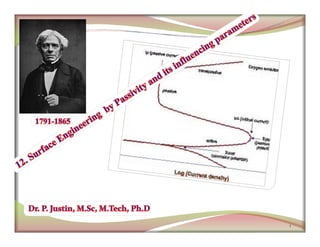
  • 5. Electrochemical basis of active-passive behavior (anodic dissolution behavior ) of a metal is illustrated in following figure. 5
  • 6.  As the potential increases towards more noble direction (anodic polarization) than EM/M +, the rate of dissolution of the metal also increases. At this point partially insulating films (probably porous metal sulphate, nitrate or chromate) on metal surface is formed .  At this point the rate corrosion is maximum and maximum current density is called critical current density (icritical). The potential corresponding to icritical is called the primary passive potential (Epp) as it represents the transition of a metal from an active state to a passive state.  The potential at which the current becomes virtually independent of potential and remains virtually stationary is called the flade potential (EF). At this point much thinner films (probably MxOy or Fe (OH)2 or FeO) on metal surface is formed and metal becomes passive. 6  The minimum current density required to maintain the metal in a passive state is called passive current density (ip). At ip, the metal dissolution occurs at a constant rate and the oxide film begins to thicken. The dissolution rate in the passive region, therefore, remains constant.  On further increase in potential leads to an accelerated rate of corrosion due the breakdown of passive films and is called transpassive potential (Etranspassive). Now the corrosion product is Fe3+ and O2 evolution, which causes a sharp increase in the current. The transpassive potential corresponding to the end of passive region, which corresponds to the initial point of anodic evolution of oxygen . This may correspond either to the breakdown (electrolysis) voltage of water, or, to the pitting potential.
  • 7. Stability of passivity is related to EF. The lower the Eo F, the easier it becomes for passivation and higher the film stability. For Cr – Fe alloys, the value ranges from 0.63 V to -0.10V with 25% chromium addition. The passive films maybe as thin as 2-10 nm, and they offer a limited electronic conductivity, and behave like semi-conductors with metallic properties rather than the properties shown by bulk oxides. 7
  • 8. In a variety of Fe-Cr alloys, Epp and icritical substantially reduced than iron because of the formation of uniform protective films. 8
  • 9. The transpassive region increase with increasing chromium content. As the film dissolves, cation vacancies are created in the oxide surface and the conductivity of the film is increased.  Metals, like Fe, Cr, Ni and Ti, show a strong active-passive behavior. The, cathodic reaction is a deciding factor in the establishment of passivity. The rate of corrosion depends upon the degree of polarization of the anode.  A metal not showing any passivity will exhibit a linear E vs log i relationship. On the other hand, a metal exhibiting passivity would exhibit a non-linear anodic polarization. 9 hand, a metal exhibiting passivity would exhibit a non-linear anodic polarization.  Metals, like zinc, magnesium and aluminum, show a passive behavior in atmospheric corrosion. The rate of corrosion depends on the degree of polarization of both the anode and the cathode.
  • 10. Parameters Definitions of Parameters Equilibrium potential (Eeq or Eo or EM/Mz+) The potential of an electrode in an electrolyte at which rate of forward reaction is balanced by the rate of reverse reaction. At equilibrium potential, the rates of the anodic (oxidation) and cathodic (reduction) processes are equal, and there is no net charge transfer. 10 charge transfer. Passive potential (Epassive) The potential at which a metal surface changes from an active to a passive state. Passive potential is defined as the potential below which the metal surface remains active and above which the metal surface remains passive. Flade potential (EF). The potential at which a metal changes from a passive state to an active state. Flade potential is defined as the potential below which the metal surface remains passive and above which the metal surface remains active.
  • 11. Transpassive potential (Etranspassive) The potential corresponding to the end of passive region which corresponds to the initial point of anodic evolution of oxygen. This may correspond either to the breakdown (electrolysis) voltage of water, or, to the pitting potential. Pitting potential (Ep). It is the potential at which there is a sudden increase in the current density due to breakdown of passive film on the metal surface in the anodic region. 11 Critical current density (icritical) The maximum current density observed in the active region for a metal or alloy that exhibits an active-passive behavior. Passive current density (ip) The minimum current density required to maintain the thickness of the film in the passive range.
  • 12.  The stainless steel (SS) 316 with 2% Mo is a better material for seawater service than SS 304 without molybdenum.  Brass, bronze and copper based alloys are highly desirable for salt water transportation, The development of alloys for controlling corrosion in specific aggressive environments is certainly one of the great metallurgical developments of the twentieth century. Iron - base alloys containing a minimum of 12 wt.% Cr are known as the stainless steels, they remain bright and tarnish - free for years, in contrast to iron . 12  Brass, bronze and copper based alloys are highly desirable for salt water transportation, however, they are vulnerable for an environment containing ammonia frequently encountered in agriculture.  Small alloying additions of copper, chromium, or nickel minimizes the atmospheric corrosion.
  • 13. 1) The alloying element may reduce either icritical (e.g., chromium alloyed with iron), or ipassive (e.g., nickel alloyed with copper)]. For the development of corrosion-resistant alloys through passivity criterion, two approaches can be possible. 13 Elements, like chromium and nickel, which have a lower icritical and ipassive than iron, reduce the icritical of iron
  • 14. *Chromium-platinum alloys have a low resistance to corrosion in oxidizing acids and a high resistance in non-oxidizing acid. 14 An increasing chromium content reduces i critical; on the other hand, decreasing pH and increasing temperature increase i critical. *In highly oxidizing conditions the corrosion potential of chromium is very near the transpassive region.
  • 15. 15 An increasing Ni content reduces both icritical and ipassive.
  • 16. 2) Alloying with noble metals having high exchange currents densities stimulates the cathodic reaction and there by increasing the anodic current density (only active EPP metals such as Ti and Cr) to the critical value for passivation with out any oxidizer. 16 If platinum is added to titanium, the rate of corrosion of titanium is not increased because, unlike chromium, titanium does not exhibit a transpassive region.
  • 17. Impact of various cathodic reactions on the corrosion current: 17
  • 18. Spontaneous passivation of titanium by galvanically coupling to platinum. 18 NOTE: Raises the possibility of anodic protection.
  • 19. If passivating potential (flade potential > EH2/H+) corrosion rate increases 19 Passivating potential too noble for couple to passivate metal. If very large Pt cathode coupled, corrosion can be increased to P.
  • 20. 1. Effect of deaeration, aeration, and stirring (velocity) on corrosion of active-passive stainless steel in neutral saltwater. 20 For an active-passive metal exposed to a diffusion controlled cathodic reaction, the corrosion rate will increase upto certain velocity levels, beyond which the corrosion rate decreases rapidly to a very low value on the onset of passivity and would remain at passive state for still higher velocities.
  • 21. 2. Effect of chloride ions and temperature: 21  Chloride ions break down the passivity and increase the rate of anodic dissolution. Breakdown of passivity by chloride ions is local and leads to pitting corrosion.  An increase in temperature generally decreases the passive range (decreases polarization) and increases the critical current density (icritical)
  • 22. 3. Effect of oxidizer (Fe2+ or CrO4 2-) concentration: Fe 2+ or CrO 4 2- 22  Corrosion rate of an active-passive alloy initially increases with oxidizer concentration (while in its active state).  As soon as passive state is reached, the corrosion rate steeply decreases to a very low value and remains at this low corrosion passive level. This region is called region of ‘borderline passivity’ in which any surface disturbance (scratching) will destabilize passivity, leading to increase in corrosion rate.  With still further increase in oxidizer concentration, corrosion rate further increases due to transpassive behavior. Fe
  • 23.  Corrosion rate is proportional to anodic current density in the active state irrespective of whether the alloy is passive type or not.  Rate of cathodic reduction must exceed icrit to ensure lower corrosion rates in diffusion controlled process. Avoid breakdown of passive films in oxidizing environments due to transpassivity.  Avoided Border line passivity and stable passive state in oxidizing conditions is essential. 23  If the cathodic reduction is activation controlled, a metal or alloy with an more active Epp is will passivate faster.  If the cathodic reduction process is diffusion controlled, a metal or alloy having a small icrit will passivate faster.
  • 24. 1. Oxide film theory  The oxide theory attributes corrosion resistance of passive metals and alloys due to the formation of a protective film on the metal surface.  There is a formation of a primary layer of lower conductivity and high porosity partially protective film on the metal surface in the beginning of passivity. As the current increases in the pores, passive layer is formed at a potential closer to the Flade potential. 24  A stable passive film is free from porosity and presents a protective barrier between the metal and the corrosive environment. 2. Adsorption theory  The adsorption theory is based on chemisorbed films. Oxygen adsorption on surfaces can reduce corrosion activity.  Uhlig in 1946 observed Flade potential of passive iron is too noble by about 0.6V due to adsorbed oxygen atoms on its surface. Adsorbed oxygen atoms significantly decrease the exchange current density, thus increasing anodic polarization, favorable for passivation.
  • 25.  Only potentiostatic approach allows a detailed study of the important parameters influencing passivity.  Galvanostatic methods are not adequate for establishing the active-passive behavior. Above icrit, the curve no longer follows the anodic curve in the passive region; suddenly jumping into the transpassive region with oxygen evolution in galvanostatic methods. 25
  • 26. 26
  • 27. 27
  • 28. 28
  • 29. 29
  • 30. 30 Show that when applied current density approaches the limiting current density the over potential at the cathode increases rapidly where as over potentialat the anode remains very small.
  • 31. 1
  • 32. Illustration of hydrogen diffusion: Hydrogen attack is a form of corrosion damage that occurs in carbon and low-alloy steels exposed to high-pressure gas at high temperatures for extended periods of time. The increased concentration of surface hydrogen favors the entrance of hydrogen atoms into the metal lattice, causing hydrogen embrittlement (loss of ductility). Some times the molecular gases (H2, CH4, NH3) produced does not dissolve in the lattice, and internal gas pressures lead to the formation of cracks or fissures in some stressed high - strength ferrous alloys, called hydrogen cracking or hydrogen blistering. 2 Illustration of hydrogen diffusion:
  • 33. Causes of hydrogen attack:  During plating operations  Pickling in sulfuric acid or hydrochloric acid after electroplating  The presence sulfur or arsenic compounds in acids favor entrance of hydrogen into the metal lattice leading to intensified cracking.  In cleaning of high strength steels in chloride or fluoride solution.  Manufacturing and fabrication processes. 3 Examples of hydrogen attack:  Decarburization in nickel alloys during heat treatment at 2012°F (1100°C) in hydrogen atmospheres.  The formation of steam in welded steels, copper, nickel, and silver by reacting with oxygen.  Formation of ammonia in molybdenum by reaction with nitrogen.  The disintegration of oxygen-containing copper in the presence of hydrogen.
  • 34. 1. Formation of hydrogen atoms at the steel surface and adsorption on the surface. 2. Diffusion of hydrogen atoms into the steel substrate. 3. Accumulation of hydrogen atoms at hydrogen traps, such as voids around inclusions in the steel matrix, leading to increased internal pressure, crack initiation and propagation, and linkage of separate cracks. Example 1: Cracks or blistering formation in the presence of hydrogen sulfide 4  Accumulation of hydrogen inside builds up high internal pressure inside the steels and creates fissures or cracks preferentially at the grain boundary or non-metallic inclusions.
  • 35. Example 2: Decarburization (High temperature hydrogen attack) At temperatures above 230°C and hydrogen partial pressure above 100psi (7kg/cm2), atomic hydrogen reacts with the carbon component in the steel to form methane.  Accumulation of methane inside builds up high internal pressure inside the steels and creates fissures preferentially at the grain boundary or non-metallic inclusions.  Since neither molecular hydrogen or methane is not capable of diffusion through the steel 5  Since neither molecular hydrogen or methane is not capable of diffusion through the steel lattice, so these gases accumulate in the steel matrix.
  • 36. 1. Hydrogen embrittlement 2. Hydrogen blistering (Hydrogen induced cracking) 3. High temperature hydrogen attack (hydrogen damage) The loss of ductility due to the entrance of hydrogen atoms into the metal lattice is called hydrogen embrittlement. 6
  • 37. Difference between SCC and hydrogen embrittlement:  SCC begins at the surface, whereas hydrogen embrittlement begins internally.  The magnitude of corrosion is higher at the origin of SCC than observed with hydrogen embrittlement. In SCC a specimen becomes more anodic and cracking is accelerated on applying a current. 7 applying a current.  In hydrogen embrittlement a specimen becomes more anodic and cracking is accelerated on applying a current.
  • 38. Prevention of hydrogen embrittlement: 1. Proper plating and pickling conditions and coatings: 1. Avoid Chlorides and fluorides in plating and pickling baths. 2. Provide low temperature aging 160oC—370oC for long time after plating. 3. Very-high-strength steels should not be subjected to cadmium plating or hot dip galvanizing. 4. Hydrogen embrittlement of titanium can be avoided if the ratio of HNO3/HF exceeds 10. 8 1. The removal of hydrogen in steels can be carried out by heat treatment at temperatures up to 392°F (200°C) after plating, a process known as baking. 2. Hydrogen can be removed from titanium, zirconium, and their alloys by annealing in vacuum. 2. Heat treatment: 3. Alloying additions: 1. Alloys with nickel or molybdenum (< 0.75%) or vanadium reduce susceptibility 2. Carbon content should be kept low.
  • 39. 3. Add inhibitors to pickling baths to minimize hydrogen embrittlement. 4.The embrittlement of steel in gaseous environments can be inhibited by adding 0.4 to 0.7 vol.% oxygen 5. Use low hydrogen welding rods. 9
  • 40. A crack or fissures in some stressed high - strength ferrous alloys due to the formation of hydrogen molecules into the metal matrix is called hydrogen blistering or hydrogen induced cracking. 10  Accumulation of hydrogen inside builds up high internal pressure inside the steels and creates fissures or cracks preferentially at the grain boundary or non-metallic inclusions.
  • 43. Hydrogen blistering in the wall of a container: 13
  • 44. Prevention of hydrogen blistering or crack: 1. The decreased solubility of hydrogen in bcc structural steel compared to the fcc structure steel 2. A reduced cooling rate inhibits the formation of martensite and also allows hydrogen to be slowly released from the steel, there by eliminating the damage. 3. Hot-rolled steel or annealed steel is preferable to cold-rolled steel. 4. The use of low-sulfur, calcium-treated, or argon-blown steels is recommended. 1. Heat treatment: 14 4. The use of low-sulfur, calcium-treated, or argon-blown steels is recommended. 2. Alloying additions: 1. Using steel resistance to hydrogen induces cracking, such as steels containing Cu or cobalt. Carbon content should be kept low. 2. Treatment with synthetic slag (calcium aluminate, calcium silicate and calcium fluoride) or the addition of rare earth metals can favor the formation of less detrimental globular sulfides.
  • 45. 3. Inhibitors can minimize the hydrogen blistering because the cathodic reduction of hydrogen ions is also retarded. 4.The Coating or lining. A rubber lining on steel, or the cladding of steel with austenitic stainless steel or nickel can minimize the hydrogen blistering. 5. The incidence of hydrogen blistering can be greatly reduced by removing such hydrogen evolution poisons as sulfides, arsenic compounds, and phosphorus- containing ions from the environment. 15 A crack or fissures in some stressed high - strength ferrous alloys due to the formation of other than hydrogen molecules like methane or ammonia into the metal matrix is called high temperature hydrogen attack (hydrogen damage)
  • 47. 17
  • 48. 1
  • 49. Almost all metals, alloys and materials of technological interest will oxidize and corrode at high temperatures, leading to scaling, loss of material and changes in physical properties. This is sometimes called “ dry ” corrosion, in contrast to “ wet ” corrosion. Gaseous attack is not limited to oxygen however, with sulphur-bearing gases, carbon oxides, nitrous oxides and halogens attacking materials in a different manner. Furthermore, high temperature corrosion is not restricted to the gaseous phase – solid ash 2 Furthermore, high temperature corrosion is not restricted to the gaseous phase – solid ash and salt deposits contribute to the corrosive effect. In the liquid phase, molten metals and molten salts pose their own unique variety of challenges Usually ions, rather than atoms, migrate through solid oxides, sulfides, or halides. The migrating ions are not hydrated, and they diffuse simultaneously with electrons. For copper oxidizing in O2, or silver tarnishing in a contaminated atmosphere, the solid electrolytes are Cu2O and Ag2S, respectively.
  • 50. Present trend in most high - temperature processes industries is to increase the operating temperatures in order to obtain to increased efficiency, but also to reduce emissions, thereby helping to achieve sustainability and improving economics. For example, partially insulating the combustion chamber on a Diesel engine increased the piston surface temperature from 450° C to 900° C, and it also increased the combustion efficiency (decreased fuel consumption) by 20% and reduced the nonburned hydrocarbons emission . So, high temperature corrosion is a widespread problem in various industries such as: 3 such as: Power generation (nuclear and fossil fuel) Heat treating, Refining and petrochemical Mineral and metallurgical processing Chemical processing, pulp and paper Refining and petrochemical Automotive and waste incineration
  • 51. An oxidation reaction between a metal (M) and the oxygen gas (O2) can be written as Thermodynamically, an oxide will form on the surface of a metal when the oxygen potential in the environment is greater than the oxygen partial pressure (dissociation pressure ofthe oxide) in equilibrium with the oxide. 4
  • 52. A graphical representations of standard free energies for the formation of oxides as a function of temperature are known as Ellingham/Richardson diagrams. The partial pressure of oxygen required for oxidation at various temperatures can be read from the nomographic scale given on the right side of the plot. The strong oxide former is shown at the bottom (more negative value of ΔGO ) of the plot, while the weakest oxide forming metal is shown on the upper part of the curve. Ores can be reduced by carbon only if its ∆Go is above that one of the carbon oxidation reaction. Practical refining temperature are generally limited to about 1500o K. 5 reaction. Practical refining temperature are generally limited to about 1500o K. A given metal can reduce the oxides of other metals whose lines lie above theirs on the diagram. so magnesium can reduce titanium oxide to metallic titanium (or Cr or Ni or Zn). Used to determine the ratio of carbon monoxide to carbon dioxide (PCO/PCO2) that will be able to reduce the oxide to metal at a given temperature. The harder the oxide is to reduce, the greater the proportion of CO needed in the gases.
  • 53. 6
  • 54. 7
  • 55. 8
  • 56. Pilling-Bedworth ratio describes the type of oxide film that forms on a metal surface during oxidation. Three types of oxides may form, depending on the volume ratio between the metal and the oxide. (a) magnesium produces a porous oxide film. 9 (b) aluminum forms a protective, adherent, nonporous oxide film, and (c) iron forms an oxide film that spills off the surface and provides poor protection.
  • 57. The Pilling Bedworth ratio (PBR) is defined as the ratio of the molar volume of metal to the molar volume of the oxide formed on it. It says whether the volume of reaction product is greater or less than the volume of metal from which the product forms. 10 A0 Molecular (or formula) weight of the oxide AM Atomic weight of the metal ρM Metal density ρ0 Oxide density
  • 58. PBR 1 -a protective scale is predicted to form (Al2O3,NiO,SiO2, CrO2) -compressive stresses in oxide film → the scale remains adherent to the substrate metal and uniformly cover metal surface PBR 1 -the scale is formed in tension and tends to be non-protective (MgO, CaO, Li2O, FeO, Cu2O) -tensile stresses in oxide film → brittle oxide cracks -alkali metals have a violent reaction when exposed to air PBR 1 -more thick scales are non-protective (TiO2, WO3) 11 PBR 1
  • 59. The Pilling - Bedworth ratios for some metals are listed in following table. As shown, this ratio does not accurately predict oxidation resistance, although there is some qualitative agreement. 12 In addition to the Pilling – Bedworth ratio, protection by an oxide depends on good adherence of the oxide to the substrate, low vapor pressure and high melting temperature of the oxide, slow oxide growth rate, high thermodynamic stability, and low electrical conductivity or low diffusion coefficients for metal ions and oxygen.
  • 60. The density of aluminum is 2.7 g/cm3 and that of Al2O3 is about 4 g/cm3. Describe the characteristics of the aluminum-oxide film. Compare with the oxide film that forms on tungsten. The density of tungsten is 19.254 g/cm3 and that of WO3 is 7.3 g/cm3. Example 1: Solutions: 13
  • 61. Since P-B ~ 1 for aluminum, the Al2O3 film is nonporous and adherent, providing protection to the underlying aluminum. However, P-B 2 for tungsten, so the WO should be non-adherent and non- 14 However, P-B 2 for tungsten, so the WO3 should be non-adherent and non- protective.
  • 62. The three main equations that express weight gain per unit area or thickness (W) of film or scale forming on any metal within time (t) are (1) the linear, (2) the parabolic, and (3) the logarithmic. The k represents corresponding rate constant. 1. Linear equation: The rate of oxidation remains constant with time (or dy/dt = kL= slope) and is independent of the amount of gas or metal previously consumed in the reaction. Such reactions usually take place by surface or phase 15 Such reactions usually take place by surface or phase boundary reactions. Alkali metals and alkaline earth metals oxidize linearly and have oxide to metal volume ratio less than 1. The linear rate law is usually followed when a protective scale cracks or spalls (WO3 or MoO3), leading to direct access of gas to metal. Other examples: Tantalum and columbium (niobium)
  • 63. 2. Parabolic equation: The parabolic rate law assumes that the diffusion of metal cations or oxygen anions or migration of electrons through the scale is the rate controlling step and is derived from Ex: Fe, Co, Ni and Cu 16 the rate controlling step and is derived from Fick's first law of diffusion. It is an inversely proportional to scale thickness. Most metals and engineering alloys follow parabolic kinetics at elevated temperatures and have oxide to metal volume ratio 1-2, which is protective in nature. The parabolic law was first derived by Wagner, assuming diffusion of charged species through the oxide layer.
  • 64. 3. Logarithmic behavior: The rate of reaction rises very fast in the beginning and then slows down, either following a direct or inverse logarithmic law. It is generally observed with thin oxide layers ( 1000 Å) at low Ex: Al, Cu and Fe 17 observed with thin oxide layers ( 1000 Å) at low temperatures or slightly elevated temperatures of metals like Al, Cu and Fe. It is often difficult to distinguish between the logarithmic and the inverse logarithmic equations. These are based on the transport of either ions or electrons (electrical potential gradent) through thin oxide layers.
  • 65. Ex: Zirconium and hafnium 18
  • 66. 19
  • 67. 20
  • 74. 27
  • 75. 1
  • 76. Anodization involves thickening of oxide layers on metals such as Al, Mg, Ti, and their alloys through application of a voltage or current (100 or more A/m2) to a metal surface that is immersed in a suitable electrolyte. 2 Anodizing developed around 1917 with first US patent in 1925 The oxide so formed must be hydrated to improve its protective qualities by exposing anodized articles to steam or hot water for several minutes, a process called sealing.
  • 77. Cathode Rn.: Anode Rn.: Total Rn.: The hydrogen ions moving to the cathode where they are reduced to 3  The anodic films formed can be either porous or nonporous, depending on which electrolyte is used.  Sulfuric, chromic, phosphoric and oxalic acid electrolytes form both barrier and porous layers while boric acid electrolytes produce only barrier films.  Sulfuric acid is the most widely used electrolyte. To obtain the maximum corrosion resistance, the porous coating must be sealed after dying. The hydrogen ions moving to the cathode where they are reduced to hydrogen gas. At the anode surface they react with the oxide/hydroxide ions to form aluminum oxide.
  • 78. 4
  • 79. Porous-type coatings exhibit a duplex structure consisting of an inner barrier layer and a crystalline outer layer that consists of a regularly spaced array of pores in certain cases. 5 As with barrier film formation, Al3+cation and O2- and OH- anion transport occurs during anodization, but in this case Al3+ is ejected into solution instead of participating in film formation. The Al3+ then reprecipitates on the previously existing barrier layer leading to the formation of a porous outer layer.
  • 80. 6
  • 81. Bright anodizing :  Bright anodizing is a special type of anodizing(in combination with polishing) when glossy or shiny surfaces are required.  Finishing trim components, automotive applications like window trims and bumpers. Hard anodizing :  Hard anodizing is a term used to describe the production of anodic coatings with film hardness (350-1400 HV) or abrasion resistance as their primary characteristic. 7 abrasion resistance as their primary characteristic.  Hard anodized aluminum shows a good heat resistance, and a hard anodic oxide coating of 75µm withstands short exposures to temperatures oft he order of 2000 0C.  In industry for components which require a very wear resistant surface such as pistons, cylinders, and hydraulic gear.
  • 82. 8
  • 83. 9
  • 84. 10
  • 85. 11
  • 86. TiO2 films have attracted attention for a great variety of applications such as: dye-sensitizing solar cells, photo catalysis, gas sensing … TiO2 nanoporous structures are desirible for these applications due to their high surface area TiO2 Nanotubes Arrays fabricated by anodizing process A number of techniques have been used to make TiO2 films, including: Sol-gel, Chemical vapor deposition Pulsed laser deposition
  • 87. DC Power supply (+) (-) e - e - Electrolyte (HF) Anode Cathode Oxide Electrolyte Oxide Ti 4+ O 2- Ti H2O H2O Ti TiO2 Nanotubes Arrays fabricated by anodizing process Ti Oxide Ti 4+ Ti TiO2 Ti 4+ Ti TiO2 Ti Tubular morphology TiO2 barrier oxide
  • 88. Top view Side view TiO2 Nanotubes Arrays fabricated by anodizing process Tube wall: ~10 nm Tube hole diameter: ~100 nm Tube height : ~ 300 nm Anodizing Voltage: 20V Anodizing Time: 20 min 100 nm 10 nm ~300 nm Morphology Description Forming Conditions Void volume estimated ~ 77 % HF Solution
  • 89. TiO2 Nanotubes Arrays fabricated by anodizing process
  • 90. 2 min 5 min Tube size with varied anodizing time (10V) TiO2 Nanotubes Arrays fabricated by anodizing process 10 min 20 min
  • 91. TiO2 nanotubes formed at 20 V for 20 min in HF solution. no heat treatment 300 oC, 3h heat treatment 700 oC, 3h heat treatment TiO2 Nanotubes Arrays fabricated by anodizing process 2 0 3 0 4 0 5 0 6 0 7 0 8 0 9 0 0 1 0 0 0 2 0 0 0 3 0 0 0 4 0 0 0 5 0 0 0 T (2 0 1 ) T (1 0 3 ) T (1 0 2 ) T (0 0 2 ) T (1 0 0 ) T (1 0 1 ) R (1 1 0 ) R (1 0 1 ) R (2 1 1 ) A (1 0 1 ) H T (7 0 0 o C , 3 h ) N T H T (3 0 0 o C , 3 h ) N T A n o d iz e d (2 0 V ) T iO 2 N T Intensity 2  no heat treatment 300 oC, 3h heat treatment 700 oC, 3h heat treatment
  • 92. General description of TONT TiO2 Nanotubes Arrays fabricated by anodizing process 100 nm TiO2 Nanotubes TiO2 Nanotubes coated with Pt or Pd 100 nm
  • 93. What is Anodic Porous Alumina?  Aluminum oxide grown on an Al substrate in an electrolytic cell. The resulting structure consists of an array of tunable nanometer-sized pores surrounded by an alumina backbone. Purpose:  To understand the mechanisms involved in the growth and ordering of anodic porous alumina. Motivation: Why do we want to fabricate nanostructures?  Interest in using anodic porous alumina as a nano- template to fabricate nanometer-sized structures (e.g. nanofabrication of quantum dots). 1. Fundamental physical interest in the nanometer size regime. Properties of nano-sized structures are different from their bulk and molecular counterparts. 2. Technological applications as electronic and optical devices.
  • 94.  Microfiltration.  Optical waveguides and photonic crystals for optical circuits. Porous Alumina used as optical waveguide. H. Masuda, et. al., Jpn. J. Appl. Phys. 38, L1403 (1999). Commercially available Anopore filter. http://www.2spi.com/catalo g/spec_prep/filter2.html 1. Physics:  Explore optical, electrical, and magnetic quantum confinement. 2. Engineering: for optical circuits.  Template for carbon nanotube growth for electronic, mechanical applications.  Ordered arrays of quantum dots for lasers, photodetectors.  ULSI memory devices and ICs. Ordered arrays of carbon nanotubes fabricated using a porous alumina template. J. Li, et al., Appl. Phys. Lett. 75(3), 367 (1999).
  • 95. Fabrication  Anodize aluminum in electrolyte (e.g. Oxalic Acid) Two main types of anodic oxide films can be grown depending on the nature of the electrolyte: 1. Barrier-Type Films:  Grown Oxide Insoluble in Electrolyte  Nearly Neutral Electrolytes (pH 5-7) 2. Porous-Type Films:  Grown Oxide Slightly Soluble in Electrolyte  Aqueous Sulfuric, Oxalic, and Phosphoric Acid Electrolytes
  • 96.  Anodize aluminum in electrolyte (e.g. Oxalic Acid).  Oxide grows at the metal/oxide and oxide/electrolyte interfaces, pores initiate at random positions by field- assisted dissolution at the oxide/electrolyte interface.  Ordering requires appropriate potentials and long anodization times.  Ordering results from repulsion between neighboring pores due to mechanical stress at the metal/oxide interface. Apparatus interface. H. Masuda and K. Fukuda, Science 268, 1466 (1995). Resulting Structure
  • 97.  Oxide growth proceeds via ionic conduction and reaction of Al cations and oxygen containing anions under the influence of an applied field. (e.g. 2Al+ + 3OH-  Al2O3+3H++6e-)  Pores initiate at random positions through field-assisted dissolution of the oxide at the oxide/electrolyte interface. V.P. Parkhutik, and V.I. Shershulsky, J. Phys. D:Appl. Phys. 25, 1258 (1992). oxide/electrolyte interface.  Initially oxide growth dominates. (I)  Dissolution becomes competitive, barrier layer thins, and pores initiate. (II)  Approaches steady state where both mechanisms occur at roughly the same rate. (III and IV)
  • 98. Ordered Nano-Templates  Tunable diameters and spacings from 20 nm to 500 nm.  Polycrystalline structure: ordered micron-sized domains, defects at grain boundaries.  Low temperature growth produces unordered 4-10 nm arrays. Ordered Oxalic Near-Ordered Sulfuric
  • 99. Ordered Growth of Porous Alumina  Ordered pore arrays obtained in three different electrolytes for long anodization times and appropriate voltages (specific for each electrolyte).  Polycrystalline structure with perfectly ordered domains a few microns in size. Defects occur at grain boundaries.
  • 100.  Porous alumina used as an evaporation mask to grow quantum dots. Thermally Evaporated Nano-Dots: Gold H. Masuda et al. , Jpn. J. Appl. Phys. 35, L126 (1996).
  • 101. Overview: Mask Processing AFM of Unopened Barrier Layer (1 mm x 1 mm) 1. 2. 3. 1. Anodize sample for a long time to achieve ordered pores. 2. Chemically remove the alumina in a mixture of phosphoric and chromic acid. 3. Anodize sample for a short time. 4. Coat top surface of alumina with a polymer 7. Remove collodion and place alumina on desired substrate. H. Masuda et al. , Jpn. J. Appl. Phys. 35, L126 (1996). 4. 5. 6. 7. alumina with a polymer (collodion) to protect it from further processing. 5. Remove Al Substrate in a saturated HgCl2 solution. 6. Remove the barrier layer in 5 wt.% Phosphoric Acid.
  • 102.  Apply black wax around the area that you want to anodize.  Electropolish Aluminum surface to make it smooth.  Anodize the sample that should be ordered for 15 hours in oxalic acid.  Anodize the sample that should be disordered for 1 hour in oxalic acid.
  • 103.  Chemically remove the alumina in a mixture of phosphoric and chromic acid.  Anodize both samples for one hour in oxalic acid.  Coat top surface of alumina with a polymer (collodion) to protect it from further processing.
  • 104.  Remove Al substrate in a saturated HgCl2 solution.  Use a piece of silicon to pick up oxide and polymer and move to 5 wt. % phosphoric acid. This removes barrier layer.  Remove collodion and place alumina on desired substrate- silicon for SEM characterization and quartz for UV-Vis characterization.
  • 105. Ordered AAO (100k magnification) Unordered AAO (100k magnification) Ordered Au dots (100k magnification) Unordered Au dots (100k magnification)
  • 106. 1
  • 107. The term “conversion coating” is used to describe coatings in which the substrate metal provides ions that become part of the protective coating due to the reaction of the metal surface with a chemical medium. Conversion coating has a dimensional growth and final product have greater volume than the original metal. The coating layers are composed of inorganic compounds that are chemically inert. The corrosion products thus formed build a barrier protection for the substrate metal. This barrier reduces the active surface 2 for the substrate metal. This barrier reduces the active surface area on the base metal, thereby delaying the transport of oxidizers and aggressive species. By so doing, the coating inhibits the formation of corrosion cells.
  • 108.  To improve the adherence of the organic layers by the formation of a uniform corrosion product layer  To provide a uniform, grease-free surface and electrically insulating barrier layers with high surface tension  removal of contaminants (oils, fats, particles) To provide active corrosion inhibition by reducing the rate of the oxygen reduction reaction, or by passivating the metallic substrate Conversion layers are used for various reasons, including: 3 oxygen reduction reaction, or by passivating the metallic substrate  Secondary barrier action of corrosion products Conversion coatings belonging in this group are phosphate, chromate, oxide, and anodized coatings. These coatings are composed of corrosion products that have been formed artificially by chemical or electrochemical reactions in selected solutions.
  • 109. Phosphate coating transforms the base metal surface (e.g., iron, steel, zinc, aluminum, and their alloys.) into phosphate layers by treating with a weak phosphoric acid solution of iron, zinc, or manganese phosphate.  Phosphate films are formed by the dissolution of base metal and the precipitation of phosphate films.  The metal surface must be free of greases, oils, and other carbonaceous materials 4  The metal surface must be free of greases, oils, and other carbonaceous materials before immersion in the phosphating solution or before spray application.  Baths operating at 120°F (50°C) have pH values of approximately 2 while those operating below 120°F (50°C) have pH values of approximately 3. The zinc phosphate coating is basically the result of a corrosion process. Reactions of iron and steel in a zinc phosphate solution are as follows:
  • 110. 5 With these reactions, the phosphate film consists of phosphophyllite and Hopeite.
  • 111. 6
  • 112. 7
  • 113. Applications:  Phosphating increases the uniformity in the surface texture and surface area, which improves paint adhesion, and in turn increases the service life of a paint film. -----------Useful preparation for painting of automobiles  They are porous and so make an attractive base for application of paints and organic coatings.  Phosphate solubility's are lowest in the pH range of 6 to 8. They are stable in neutral environments and are non-electric conductive compounds. 8 stable in neutral environments and are non-electric conductive compounds. Limitations :  Phosphate film deposits on cathodic areas and anodic sites remain in the form of pinholes. Consequently, the continuity of phosphate films is not as good as those of anodic oxide and chromate films.  Alkaline residues on the surface of the base metal lead to under film corrosion.
  • 114. 9
  • 115. 10
  • 116. Chromate coating transforms the base metal surface (e.g., Al and its alloys, Mg, Zn, and Cd) into amorphous gel- like continuous layer consisting of insoluble chromium compounds and soluble hexavalent chromium compounds by treating with a source of hexavalent chromium ion (e.g., chromate, dichromate, or chromic acid) and an acid.  The coating structure provides a secondary barrier, inhibiting action, and also good 11  The coating structure provides a secondary barrier, inhibiting action, and also good adhesion for lacquer films. Chromate coatings provide their corrosion resistance based on the following three properties:
  • 117. Chrome baths always contain a source of hexavalent chromium ion (e.g., chromate, dichromate, or chromic acid) and an acid to produce a 12 (e.g., chromate, dichromate, or chromic acid) and an acid to produce a low pH, which is usually in the range of 0 to 3. During the reaction, hexavalent chromium is partially reduced to trivalent chromium, forming a complex mixture consisting largely of hydrated hydroxides of both chromium and aluminum:
  • 118. Chromic acid processes: There are two types of processes by which conversion coatings can be produced: chromic acid processes and chromic-phosphoric acid processes.  This conversion coating is yellow to brown in color and consists primarily of oxide Cr2O3, better described as an amorphous hydroxide Cr(OH)3. 13 Chromic-phosphoric acid processes: described as an amorphous hydroxide Cr(OH)3.  This conversion coating is greenish in color and consists primarily of hydrated chromium phosphate with hydrated chromium oxide concentrated toward the metal.
  • 119. Applications:  Chromium conversion coatings can be used as a base for paints or alone for corrosion protection.  Previously it was described how the leached hexavalent chromium acts as an anodic inhibitor by forming passive films over defects in the coating. Limitations : 14  The longer the time of wetness or direct atmosphere, the shorter the service life of the coating because chromate coatings absorb moisture and moisture results in the leaching of hexavalent chromium.  A source of fluoride ions is also usually present. These fluoride ions will attack the original (natural) aluminum oxide film, and also fluoride ions prevents the aluminum ions (from base substrate) from precipitating by forming complex ions.  Because the films formed on Al by the chromic acid-phosphoric acid process contain no hexavalent chromium, they do not provide self-healing from defects.
  • 120.  Iron or steel articles to be coated are heated in a closed retort to a temperature of 1600°F (871°C), after which superheated steam is admitted.  This results in the formation of red oxide (FeO) and magnetic oxide (Fe3O4).  Carbon monoxide is then admitted to the retort, reducing the red oxide to magnetic oxide, which is resistant to corrosion. Each operation takes approximately 20 min Such coatings, blue, brown, or black in color, consist mostly of Fe3O4 and, phosphate coatings, are not protective against corrosion. 15 Iron and steel may also be coated by electrolytic means. The article to be coated is made the anode in an alkaline solution (anodic oxidation). These coatings are primarily for appearance, such as for cast iron stove parts.
  • 121. 1
  • 122. 2  Plasma is an ionized gaseous cloud composed of free electrons, positive ions, neutral atoms and molecules because of its unique properties.  Some have referred to it as the fourth state of matter.  Plasma is generated whenever sufficient energy is imparted to a gas to cause some of it to ionize.  State of ionized gas (plasma) is possible when the mean kinetic energy of plasma particles is of the order of magnitude of the ionization energy Plasma :
  • 123. 3 plasma spraying, a thermal spray process in which a non-transferred arc is a source of heat that ionizes a gas which melts the coating material and deposit it on to the work piece. Plasma spray deposition is a process that combines particle melting, quenching and consolidation in a single operation. Non transferred arc plasma gun Schematic
  • 124. 4 1. When the plasma jet is formed, a powder through nozzles carried by the carrier gas is injected into it. 2. Accelerated and melted powder particles leave the plasma jet in the form of molten particle stream. 3. The molten particles bombard the substrate surface deposited on the surface. 4. Then they cool and forming a coating. 5. Every molten particle has a high thrust which leads to high bond strength of the coat. 6. The temperature of the substrate remains below 100 ˚C. 7. Thickness of the coat varies between 0.3 and 1 mm, but it may be also up to 5 mm Plasma spraying process
  • 125. 5 8. The temperature at the core of the plasma jet is 10,000-15,000 K. 9. Metal or ceramic particles injected into the plasma undergo rapid melting and at the same time are accelerated. 10. These molten droplets moving at high velocities, exceeding 100 m/s, impact on the surfaces of the substrate forming adherent coating. 11. The coating is incrementally built up by the impact of successive particles by the process of flattening, cooling and solidification. 12. By virtue of the high cooling rates, typically 105 to 106 K/sec., the resulting microstructures are fine-grained and homogeneous  The plasma spray process is mostly used in normal atmospheric conditions (air or atmospheric plasma spray - APS).  It also has the ability to operate in an inert atmosphere using method of Low Pressure Plasma Spraying (LPPS) or Vacuum Plasma Spraying (VPS).  This enables deposition of materials sensitive to oxidation (Ti, Mg).
  • 127. 7  Plasma sprayed coatings are extensively used for high temperature chemical barrier applications.  Plasma spraying is used for both metallic and non-metallic materials usually more suitable for high melting point materials like refractory materials and cremets.  Temperature in the plasma arc can be as high as 2,000°C to 20,000°C and is capable of melting anything. Requirements for the plasma spraying  Roughness of the substrate surface  Cleanliness of the substrate surfaces  Bond coat  Cooling water
  • 128. 8 Process parameters for the plasma spraying  Arc power  Plasma gas  Carrier gas  Mass flow rate of powder  Powder related variables(size,MP etc.,)  Stand-0ff-distance (Spray Distance)  Spraying angle  Substrate cooling  Angle of powder injection
  • 129. 9 Industrial applications of the plasma spraying  Steel industry  Aircraft industry  Paper industry  Gas turbine industry  Glass industry  Automotive industry and production of combustion engines  Medical industry  Chemical plants  Foundry mills  Textile industry
  • 130. 10 Advantages of Plasma spraying 1. Very flexible in coating material selection and optimization for specific resistance to corrosive environments and particle abrasion/erosion. 2. Unique alloys and microstructures can be obtained with thermal spraying which are not possible with a wrought material. 3. Costs of the coating solution are normally significantly lower than those of a highly alloyed bulk material. 4. Forms microstructure with fine, equiaxed grains and without columnar boundaries. 5. Produces deposits that do not change in composition with thickness (length of deposition time). 6. Can change from depositing a metal to a continuously varying mixture of metals ceramics (i.e. functionally graded materials).
  • 131. 11 7. High deposition rates (4kg/h). 8. Fabricates freestanding forms of virtually any material or any materials combination. 9. Process materials in virtually any environment e.g. air, reduced pressure inert gas, high pressure etc.
  • 132. 1
  • 133. 2 Sputter deposition: When a solid surface is bombarded with energetic ions, surface atoms of the solid are scattered backward due to collisions between the surface atoms and the energetic particles. The phenomenon is called “back-sputtering” or simply “sputtering Several types of sputtering systems are used in practice including DC diode, RF-diode, magnetron diode, and ion beam sputtering.
  • 134. 3  Operation pressure (~1-100mTorr)  Power (few 100W)  For DC sputtering, voltage -2 to -5kV.  Additional substrate bias voltage.  Substrate temperature (20-700oC) Major sputtering process parameters: Sputtering process can be run in DC or RF mode In addition to IC industry, a wide range of industrial products use sputtering:  LCD  computer hard drives  hard coatings for tools  metals on plastics.
  • 135. 4 Sputter deposition advantages 1. Able to deposit a wide variety of metals, insulators, alloys and composites. 2. Replication of target composition in the deposited films. 3. Capable of in-situ cleaning prior to film deposition by reversing the potential on the electrodes . 4. Better film quality and step coverage than evaporation. 5. More reproducible deposition control – same deposition rate for same process parameters (not true for evaporation), so easy film thickness control via time. 6. Can use large area targets for uniform thickness over large substrates. 7. Sufficient target material for many depositions. 8. No x-ray damage.
  • 136. 5 Disadvantages: 1. Substrate damage due to ion bombardment or UV generated by plasma. 2. Higher pressures 1 –100 mtorr ( 10-5 torr in evaporation), more contaminations unless using ultra clean gasses and ultra clean targets. 3. Deposition rate of some materials quite low. 4. Some materials (e.g., organics) degrade due to ionic bombardment. 5. Most of the energy incident on the target becomes heat, which must be removed.
  • 137. 6 Mechanisms of sputtering and alloy sputtering  The ion impact may set up a series of collisions between atoms of the target, possibly leading to the ejection of some of these atoms. This ejection process is known as sputtering.  Here we are interested in sputter deposition. Of course sputter can also be used as an etching method (the substrate to be etched will be the ‘target’), which is called sputter etching.  Unlike evaporation, composition of alloy in film is approximately the same as target.  Target NOT melted, slow diffusion (no material flow) mixing.  When target reaches steady state, surface composition balances sputter yield.
  • 138. DC plasma  Plasma is ionized gas, with nearly equal number of ions and electrons, plus neutrals (un-ionized molecules including those at ground state and excited state; free radicals such as atomic O, H, F – but no free radicals for Ar plasma).  Glow is due to de-excitation of excited Ar. So glow only exists where there are lots of electrons to excite Ar.  Cathode glow region: very close to cathode, secondary electrons are created by Ar bombardment of target material.  Cathode dark space/sheath: electrons pass too fast with little excitation.  Anode sheath: electrons lost to anode due to its faster random movement
  • 139. Sputter yield The sputter yield S, which is the removal rate of surface atoms due to ion bombardment, is defined as the mean number of atoms removed from the surface of a solid per incident ion and is given by S=Atoms removed/Incident ions Sputtering is caused by the interactions of incident ions with target Surface atoms. • Energy of incident ions • Target materials • Incident angles of ions • Crystal structure of the target surface. Sputter yield factors
  • 140. 9 1 .Weight loss of target 2. Decrease of target thickness 3. Collection of the sputtered materials 4. Detection of sputtered particles in flight Sputter yield Measurement methods RF (Radio frequency ) sputter deposition 1. Good for insulating materials because, positive charge (Ar+) build up on the cathode (target) in DC sputtering systems. Alternating potential can avoid charge buildup 2. When frequencies less than 50kHz, both electrons and ions can follow the switching of the anode and cathode, basically DC sputtering of both surfaces.
  • 141. 3. When frequencies well above 50kHz, ions (heavy) can no longer follow the switching, and electrons can neutralize positive charge buildup on each electrode during each half cycle. 4. As now electrons gain energy directly from RF powder (no need of secondary electrons to maintain plasma), and oscillating electrons are more efficient to ionize the gas, RF sputter is capable of running in lower pressure (1-15 mTorr), so fewer gas collisions and more line of sight deposition.
  • 142. 11  For symmetric target-substrate configuration, sputtering of both surfaces will occur, though in the opposite half cycles.  When the electrode areas are not equal, the field must be higher at the smaller electrode (higher current density), to maintain overall current continuity.  It was found that voltage drop across the dark sheath of the two electrodes satisfy the relation: (A is the area of the electrode)  Thus by making the target electrode much smaller, sputtering occurs only on the target. Wafer electrode can also be connected to chamber walls, further increasing V2/V1. RF Plasma  V1 V2  A2 A1       m
  • 143. 12
  • 144. Chemical Vapor Deposition (CVD) SHRIDEVI S BHAT 06/09/2013
  • 145. Introduction • CVD is a chemical process used to produce high-purity, high-performance solid materials. • This technique is suitable for the manufacture of coatings, powders, fibers and monolithic components. • This technique is often used in many thin film applications. • By varying the experimental conditions—substrate material, substrate temperature, composition of the reaction gas mixture, total pressure gas flows, etc.— materials with different properties can be grown.
  • 146. Definition and Types Chemical vapour deposition may be defined as the deposition of a solid on a heated surface from a chemical reaction in the vapour phase. It belongs to the class of vapour-transfer processes which is atomistic in nature, that is the deposition species are atoms or molecules or a combination of these. Schematic of a simple thermal CVD reactor
  • 147. Sequence of events during deposition
  • 148. Classified by operating pressure:  Atmospheric pressure CVD (APCVD) – CVD at atmospheric pressure.  Low-pressure CVD (LPCVD) – CVD at sub-atmospheric pressures.  Ultrahigh vacuum CVD (UHVCVD) – CVD at very low pressure, below 10−6 Pa (~10−8 torr). Classified by physical characteristics of vapour:  Aerosol assisted CVD (AACVD) – CVD in which the precursors are transported to the substrate by means of a liquid/gas aerosol, which can be generated ultrasonically.  Direct liquid injection CVD (DLICVD) – CVD in which the precursors are in liquid form (liquid or solid dissolved in a convenient solvent). Liquid solutions are injected in a vaporization chamber towards injectors. The precursor vapours are then transported to the substrate as in classical CVD.
  • 149. Plasma methods:  Microwave plasma-assisted CVD (MPCVD)  Plasma-Enhanced CVD(PECVD) – CVD that utilizes plasma to enhance chemical reaction rates of the precursors.  Remote plasma-enhanced CVD (RPECVD) – Similar to PECVD except that the wafer substrate is not directly in the plasma discharge region.  Atomic-layer CVD (ALCVD)  Combustion Chemical Vapour Deposition (CCVD)  Hot filament CVD (HFCVD)  Hybrid Physical-Chemical Vapour Deposition(HPCVD)  Metalorganic chemical vapor deposition (MOCVD)  Rapid thermal CVD (RTCVD)  Vapour-phase epitaxy  Photo-initiated CVD (PICVD)
  • 150. Historical perspective  1960: Introduction of the terms CVD and PVD to distinguish “chemical vapour deposition” from “physical vapour deposition.”  1960: Introduction of CVD in semiconductor fabrication.  1960: CVD TiC coating on cemented carbide tools introduced and development of CVD tungsten.  1963: Introduction of plasma CVD in electronics.  1968: Start of industrial use of CVD coated cemented carbides.  1980s: Introduction of CVD diamond coatings.  1990s: Rapid expansion of metallo-organic CVD (MOCVD) for ceramic and metal deposition.  1990s: Development of cluster tools combining CVD, PVD and other processing steps in a single tool for semiconductor fabrication. Major development of CVD in optics and optoelectronics.
  • 151. Classification of CVD reactions Thermal decomposition (pyrolysis) reactions
  • 153. Metal reduction of halides Oxidation and hydrolysis reactions Carbidization and nitridation
  • 154. 1. The reaction gas dispensing system. 2. The reactor, including components for defining the gas flows. 3. The exhaust system containing a total pressure controller, vacuum pump, scrubber and/or reactant recycle system. CVD system
  • 155. • In semiconductor and microelectronic industries • In metallurgical coating industries • Optical fibers for telecommunications • Wear resistant coatings, corrosion resistant coatings, heat-resistant coatings etc. • Preparation of high temperature materials Applications
  • 156.
  • 157. 1
  • 158. 2  Thermal spraying, a group of coating processes in which finely divided metallic or nonmetallic materials are deposited in a molten or semimolten condition to form a coating. The coating material may be in the form of powder, ceramic-rod, wire, or molten materials Thermal spray coating process
  • 159. 3 Thermal spray processes Flame spray processes Electrical process Flame spray processes Molten metal Powder Wire Ceramic rod Detonation HVOF Electrical processes Non-trance arc plasma RF Plasma Wire-Electric arc
  • 160. 4 Flame spray process Flame spray coating utilizes combustible gasses to create the energy necessary to melt the coating material. Common fuel gases are hydrogen, acetylene, propane, natural gas, etc. Flame spraying process is a thermal spraying process that includes low-velocity powder flame, rod flame, and wire flame processes and high-velocity processes such as HVOF and the detonation gun (D-Gun) process based on the type of feed material . Types of flame spray processes  Molten metal flame spray  Powder flame spray  Wire flame spray  Detonation gun spray
  • 161. 5 Molten metal flame spraying, a thermal spraying process in which the metallic material to be sprayed is in the molten condition. This process is also called as Melt bath spraying(MBT). 1. Molten metal Flame spraying process Procedure/Mechanism   In MBS process the feed stack material is in molten form inside the crucible and then atomized through a nozzle.  The heated air was used to pressurize a crucible filled with molten metal and eject it out as a fine spray that would adhere to a suitable surface.  The atomizing gas, usually compressed air, is most commonly applied in pre-heated state  The mass flow of the melt can be controlled by adjusting the pressure inside the crucible.
  • 162. Principle of Molten metal flame spray technique
  • 163. 7  The molten metal process has advantages and disadvantages. Advantages :  Cheap raw materials  Use of inexpensive gases  Gun design is very basic. Dis advantages :  Gun is to be use in the manual mode  Gun can only be held in a horizontal plane  High maintenance due to high temperature oxidation and molten metal corrosion  Useful only with low melting temperature metals
  • 164.
  • 165. 9 2. Powder flame spray process Powder flame spraying, a thermal spray process in which the material to be sprayed is in powder form. Process/Mechanism 1. Feed a powder through the center bore of a nozzle where it melts. 2. The melted powder carried by the flame and air jets on to the work piece. 3. Then the melted powder deposited on the substrate and forms a film. The energy source melting and acceleration of Feed stock in PFS(Powder flame spray) is a Oxy-fuel gas Particle speed is relatively low (100 m/s), and bond strength of the deposits is generally lower than the higher velocity processes.
  • 166. 10 Principle of the powder flame Spray process  Deposition rate is similarly low in PFS  Porosity can be high and cohesive strength is generally lower.  Not only metals Ceramics also can be processed by PFS
  • 167. 11 Wire flame spraying Process wire flame spraying, spray process in which the feed stock is in wire or rod form. The diameter of the feedstock can vary in the range between less than 1mm and 8mm Process/Mechanism  Feedstock material fed axially into the flame chamber. By using the feed rollers or also by using the guns.  At the wire tip the feedstock is melted and then atomized by means of an atomizing gas.  Usually acetylene, propane or hydrogen are applied as combustion gases and compressed air as atomizing gas.  The melted feed material is sprayed on to the substrate through the nozzle and then a thin film formed on to the substrate.
  • 168. 12  Wire flame Spray is used for the deposition of Aluminum or Zinc coatings for cathodic corrosion protection of Steel structure.  WFS is also used for the noble materials like Platinum.  In this process the feedstock material is relatively expensive. Principle of the wire flame spray process
  • 169. 13  Substrate temperatures often range from 95 to 205 °C (200 to 400 °F) because of the excess energy input required for flame melting.  In most thermal spray processes, less than 10% of the input energy is actually used to melt the feedstock material. Detonation gun spraying This process is a “thermal spray process variation in which the controlled explosion of a mixture of fuel gas, oxygen, and powdered coating material is utilized to melt and propel the material to the work piece
  • 170. Process/Mechanism  Oxygen and acetylene are introduced in a barrel or tube (about1 m long), closed at one end.  The ignition of the mixture by a spark plug close to the closed end generates a detonation  Pressures around 2 MPa are generated and particles injected about in the middle of the tube are accelerated and heated, and in most cases melted.  Nitrogen is used as carrier gas to feed the feedstock material (in Powder form). Detonation gun spraying is characterized by relatively high process gas temperatures, which can be up to 4,0000c, and high particle velocities i.e.,900m/s. The high particles velocities results in high coating densities and high bond strength.
  • 171. 15  The D-Gun produces premium coatings, especially metallic and cermet ones, with properties which have been the goal of all other spraying processes to reproduce, i.e., higher density, improved corrosion barrier, higher hardness, better wear resistance, higher bonding and cohesive strength, almost no oxidation, thicker coatings, and smoother as-sprayed surfaces.  Coating porosity is low (below 1 %)  The deposition efficiency is about 90%
  • 172. 1
  • 173. 2 Coating is a layer of material, formed naturally or synthetically or deposited artificially on the surface of an object made of another material, with the aim of obtaining required technical or decorative properties.
  • 174. 3  To maintain routine control in production of surface coating.  To make improvement over the existing coating.  To increase the lives of machines or components exposed to abrasion or erosion.  Also to increase the anticorrosion, fatigue, and corrosion fatigue- resistance performance of the machining tools and dies.  The thicknesses of coatings or surface treated layers may vary from less than 100 lm to 100 mm.
  • 175. 4 Metallic Coatings Non-Metallic Coatings Such coatings are made from different metals, metal alloys and metal composites, and deposited on substrates, most often themselves metallic, by different methods. These coatings, numerous and varied, are made from organic materials (paint, rubber, plastic) and inorganic (enamels, ceramics), of natural and synthetic origin and bearing many different trade and chemical names.
  • 176. 5 1.X-Ray Diffraction 2.Electron Microscopy 2.1.Scanning Electron Microscopy 2.2.Transmission Electron Microscopy 3.Hardness Test 4.Surface Stickiness Surface Characterization Techniques
  • 177. 6 Defects in Surface Coating  Non uniform growth  Outgrowth  Undesirable crystalline Phase  Undesirable crystallographic orientation  Cracks, void and porosity in the coating