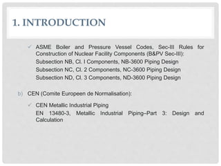
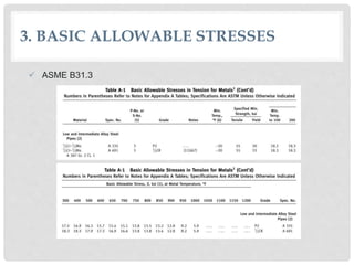
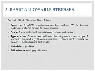
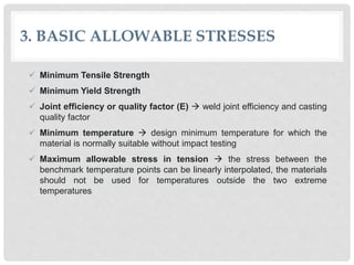
2. CONTENT
1. INTRODUCTION
2. LOADINGS TO BE CONSIDERED
3. BASIC ALLOWABLE STRESSES
4. PRESSURE DESIGN
5. STRESSES OF PIPING COMPONENTS
6. Code Application in Caesar Software
3. 1. INTRODUCTION
• Code is a set of procedures and specifications covering the
minimum requirements for material, design, fabrication, erection,
inspection, and testing.
• The main objective of piping codes is to ensure the structural
integrity of the piping systems.
• The piping is ensured of proper safety factor on structural integrity
when all code requirements are followed and satisfied.
4. 1. INTRODUCTION
• Two main systems covering the design of piping systems:
a) ASME (American Society of Mechanical Engineers)
ASME Code for Pressure Piping:
B31.1 Power Piping
B31.3 Process Piping
B31.4 Pipeline Transportation System for Liquid Hydrocarbons
and Other Liquids
B31.8 Gas Transmission and Distribution Piping Systems
B31.9 Building Services Piping
B31.11 Slurry Transportation Piping Systems
5. 1. INTRODUCTION
ASME Boiler and Pressure Vessel Codes, Sec-III Rules for
Construction of Nuclear Facility Components (B&PV Sec-III):
Subsection NB, Cl. I Components, NB-3600 Piping Design
Subsection NC, Cl. 2 Components, NC-3600 Piping Design
Subsection ND, Cl. 3 Components, ND-3600 Piping Design
b) CEN (Comite Europeen de Normalisation):
CEN Metallic Industrial Piping
EN 13480-3, Metallic Industrial Piping–Part 3: Design and
Calculation
6. 2. LOADINGS TO BE CONSIDERED
a) Pressure
Internal pressure
External pressure
Test Pressure not a design parameter. It is a quality control
measure used especially for poor-quality welds
If the longitudinal stress resulting from the test pressure exceed the
limit temporary supports are required
𝑃𝑇 = test pressure
𝑃 = design pressure
𝑆𝑇 = allowable stress at test temperature
𝑆 = allowable stress at design temperature
𝑃𝑇 =
1.5𝑃𝑆𝑇
𝑆
7. 2. LOADINGS TO BE CONSIDERED
b) Temperature
Uniform temperature distribution across the whole cross-section
creates uniform expansion used in common flexibility analysis
Variant temperature distribution across the whole cross-section
creates thermal bowing
8. 2. LOADINGS TO BE CONSIDERED
c) Weight Effects
Dead loads weight of piping components, insulation, and other
permanent loads
Live loads include the weight of fluid, snow, and ice
d) Wind Load
Can be specified either with basic wind speed or the actual wind force
Basic wind speed use ASCE-7 or UBC
Normally only two mutually perpendicular horizontal directions are
considered
Wind effect on piping inside an enclosed building or shielded by
proper object can be ignored
Wind Load.pdf
9. 2. LOADINGS TO BE CONSIDERED
e) Earthquake
Analyzed via the dynamic approach or static approach
The magnitude of acceleration (called g factor), can be determined
according to ASCE-7 or UBC
Normally applies to all three directions with smaller magnitude in
vertical direction
The earthquake load and wind load are generally not required
considered as acting concurrently
f) Passive Loads
Including support friction force, spring hanger resistance, soil
resistance, etc.
Generated because of the movements of piping
Prevent the piping from moving, do not have move the pipe
10. 2. LOADINGS TO BE CONSIDERED
g) Dynamic Fluid Loads
Vortex shedding when the fluid flows past an object or a cavity
generates force perpendicular to the flow direction has a
characteristic frequency vibration on piping
Slug flow most often exists at saturated liquid lines creates
density discontinuity imposes an impact force when flow passes a
turning bend vibration on piping
11. 2. LOADINGS TO BE CONSIDERED
Acoustic pulsation usually comes from reciprocating machine
the inlet/outlet flow rate changes periodically proportional to the
rotational speed of machine creates a periodic pressure pulsation
vibration on piping
Pressure wave created when the flow abruptly altered come
with noisy banging sound that mimic hammering (called steam/water
hammer) vibration on piping
14. 3. BASIC ALLOWABLE STRESSES
• Content of Basic Allowable Stress Tables
Spec. no ASTM specification number, prefixed “A” for ferrous
materials, prefix “B” for non-ferrous materials
Grade associated with material compositions and strength
Type or class associated with manufacturing method and scope of
inspection required, e.g.: S means seamless, E means electric resistance
welded, F means furnace butt-welded
Material composition
P-Number welding qualification
15. 3. BASIC ALLOWABLE STRESSES
Minimum Tensile Strength
Minimum Yield Strength
Joint efficiency or quality factor (E) weld joint efficiency and casting
quality factor
Minimum temperature design minimum temperature for which the
material is normally suitable without impact testing
Maximum allowable stress in tension the stress between the
benchmark temperature points can be linearly interpolated, the materials
should not be used for temperatures outside the two extreme
temperatures
16. 4. PRESSURE DESIGN
• Pipe stress analysis shall ensure that each piping component is strong
enough to contain the service pressure
• Pressure design can be accomplished by several different ways:
Use of standard components having established ratings design
by selection no calculation is involved
e.g.: flanges (ASME B16.5 and ASME B16.47), valves (ASME B16.34)
Use of standard components not having specific ratings select
the components that have the materials and nominal wall thickness same
as the connecting pipe
e.g.: butt-welding fittings (ASME B16.9, ASME B16.11, etc.)
By design calculations based on formula provided by codes
e.g.: calculations for straight pipe, smooth bend, miter bend, branch
connection, etc.
ASME B16.5 Rating Flanges.pdf
17. 4. PRESSURE DESIGN
a) Straight Pipe
Pressure resisting capability is determined by its thickness
Serves as the reference thickness for other components
Steps to select the pipe thickness:
1) Calculate the minimum required net thickness
𝑡 = minimum required net thickness
𝑃 = design pressure
𝐷 = outside diameter of pipe
𝑆 = allowable stress at design temperature
𝐸 = longitudinal joint efficiency or quality factor
𝑊 = weld strength reduction factor
𝑐 = allowance for corrosion, erosion, and others
𝑦 = coefficient value
18. 4. PRESSURE DESIGN
2) Add net thickness with allowances
3) Select commercially available nominal thickness (𝑡𝑛)
𝑡𝑚 = minimum required thickness, including mechanical, corrosion,
and erosion allowance
𝑡 = minimum required net thickness
𝑐 = allowance for corrosion, erosion, and others
𝑢 = manufacturing under-tolerance, generally 12.5%
𝑣 = manufacturing under-tolerance specified by absolute thickness,
applicable to some welded pipes rolled from plates
19. 4. PRESSURE DESIGN
Example of Calculation
• Material: ASTM A-106 Gr. B, seamless
• Design pressure: 3.5 kg/cm2
• Design temperature: 427 o C
• NPS: 10 in (OD = 273 mm)
• Corrosion allowance: 1.7 mm
• Manufacturing under-tolerance: 12.5%
• Wall thickness required calculated based on ASME B31.3:
t = 0.6 mm
• Add wall thickness with corrosion allowance and manufacturing under-tolerance:
tm= 2.6 mm
• Commercial available nominal thickness (𝑡𝑛) schedule 20 (6.35 mm)
Pipe Wall Thickness.pdf
Table A-1 ASME B31.3.pdf
Table A-1B ASME B31.3.pdf
Weld Joint Factor.pdf
Y coefficient.pdf
20. 4. PRESSURE DESIGN
b) Curved Segment of Pipe
Pipe Bends
Forged Elbows the thickness is suitable for the design pressure
given by the pressure-temperature rating of such standards
𝐼 = bend stress intensification factors
𝑅1 = bend radius
𝐷 = outside diameter
21. 4. PRESSURE DESIGN
c) Miter Bends
𝑃 = maximum allowable pressure
𝑆 = allowable stress at design temperature
𝐸 = longitudinal joint efficiency or quality factor
𝑊 = weld strength reduction factor
𝑡𝑛 = miter pipe wall thickness (measured or
minimum per purchase specification)
𝑐 = allowance for corrosion, erosion, and others
𝑟 = mean radius of pipe
𝑡 = minimum net thickness required
θ = angle of miter cut
22. 5. STRESSES OF PIPING COMPONENTS
a) Sustained Stresses
ASME B31.1
ASME B31.3
Only specifies the allowable for the longitudinal stress without giving
formula for the calculation:
𝑆𝐿 = sum of the longitudinal stresses due to
pressure, weight, and other sustained loads
𝑃 = internal design pressure
𝐷𝑜 = outside diameter of pipe
𝑡𝑛 = nominal pipe wall thickness
𝑖 = stress intensification factor
𝑀𝐴 = resultant moment loading on cross section
due to weight and other sustained load
𝑍 = section modulus
𝑆ℎ = basic material allowable stress at maximum
temperature (from the allowable stress tables)
𝑆𝐿 ≤ 𝑆ℎ
23. 5. STRESSES OF PIPING COMPONENTS
b) Occasional Stresses
ASME B31.1
ASME B31.3
𝑆𝐿 + 𝑆𝑜𝑐𝑐 ≤ 𝑘 𝑆ℎ
𝑀𝐵 = resultant moment loading on cross section
due to occasional load
𝑘 = 1.15 for occasional loads acting for no more
than 8 hours at any one time and no more than
800 hours/year
𝑘 = 1.2 for occasional loads acting for no more
than 1 hour at any one time and no more than
80 hours/year
𝑆𝐿 + 𝑆𝑜𝑐𝑐 ≤ 1.33 𝑆ℎ
24. 5. STRESSES OF PIPING COMPONENTS
c) Thermal Expansion and Displacement Stress Range
ASME B31.1
𝑆𝐸 ≤ 𝑆𝐴
𝑆𝐸 = computed displacement stress range
𝑆𝐴 = allowable displacement stress range
𝑆𝐶 = basic allowable stress at ambient temperature
𝑆ℎ = basic allowable stress at maximum metal
temperature
𝑆𝐿 = sum of the longitudinal stresses due to
pressure, weight, and other sustained loads
𝑀𝐶 = range of resultant moments due to thermal
expansion
𝑓 = stress range reduction factor
𝑖 = stress intensification factor
𝑍 = section modulus
𝑆𝐸 =
𝑖𝑀𝑐
𝑍
≤ 𝑆𝐴 = 𝑓(1.25𝑆𝐶+0.25𝑆ℎ)
when 𝑆ℎ greater than 𝑆𝐿:
𝑆𝐸 =
𝑖𝑀𝑐
𝑍
≤ 𝑆𝐴 = 𝑓{1.25(𝑆𝐶+𝑆ℎ) - 𝑆𝐿}