IMPLICATIONS OF THE ABOVE HOLISTIC UNDERSTANDING OF HARMONY ON PROFESSIONAL E...
StaticBalancing_RotatingMassess in Sigle Plane.pdf
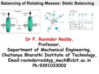
1. Dr P. Ravinder Reddy,
Professor,
Department of Mechanical Engineering,
Chaitanya Bharathi Institute of Technology,
Email:ravinderreddyp_mech@cbit.ac.in
Ph:9391033002
Balancing of Rotating Masses: Static Balancing
2.
3. UNIT-III: Balancing of Rotating Masses:
Forces on bearings due to rotating shaft carrying
several masses in several planes.
Determination of balance masses from the forces on
the bearings.
4. What is balancing of rotating members?
Balancing means a process of restoring a
rotor which has unbalance to a balanced
state by adjusting the mass distribution of
the rotor about its axis of rotation
5. Balancing
"is the process of attempting to
improve the mass distribution
of a body so that it rotates in its
bearings without unbalanced
centrifugal forces”
6.
7.
8. Mass balancing is routine for rotating
machines,some reciprocating machines,
and vehicles
Mass balancing is necessary for quiet
operation, high speeds , long bearing life,
operator comfort, controls free of malfunctioning,
or a "quality" feel
9. • Pulley & gear
shaft assemblies • Starter armatures • Airspace
components
• High speed
machine tool
spindles
• Flywheels • Impellers
• Centrifuge rotors • Electric motor
rotors • Fan and blowers
• Compressor
rotors • Turbochargers • Precision shafts
• Crank shafts • Grinding wheels • Steam & Gas
Turbine rotors
Rotating components for balancing
14. Benefits of balancing
Increase quality of operation.
Minimize vibration.
Minimize audible and signal noises.
Minimize structural fatigue stresses.
Minimize operator annoyance and fatigue.
Increase bearing life.
Minimize power loss.
15. Rotating a rotor which has unbalance
causes the following problems.
The whole machine vibrates.
Noise occurs due to vibration of
the whole machine.
Abrasion of bearings may shorten
the life of the machine.
NEED FOR BALANCING
NEED FOR BALANCING
16. Rotating Unbalance occurs due to the
following reasons.
The shape of the rotor is unsymmetrical.
Un symmetrical exists due to a machining error.
The material is not uniform, especially in
Castings.
A deformation exists due to a distortion.
17. An eccentricity exists due to a gap of
fitting.
An eccentricity exists in the inner ring of
rolling bearing.
Non-uniformity exists in either keys or key
seats.
Non-uniformity exists in the mass of flange
Unbalance due to unequal distribution
of masses
18. . Types of Unbalance
Static Unbalance: A system of rotating masses
is said to be in static balance if the combined
mass centre of the system lies on the axis of
rotation.
Dynamic Unbalance: When several masses
rotate in different planes, the centrifugal
forces, in addition to being out of balance,
also form couples. A system of rotating
masses is in dynamic balance when there
does not exist any resultant centrifugal force
as well as resultant couple.
19. Balancing of rotating masses:
The process of providing the second mass in order to
counteract the effect of the centrifugal force of the
first mass is called balancing of rotating masses.
Static Balancing:
The net dynamic force acting on the shaft is equal to
zero. This requires that the line of action of three
centrifugal forces must be the same. In other words,
the centre of the masses of the system must lie on the
axis of the rotation. This is the condition for static
balancing.
Dynamic Balancing
The net couple due to dynamic forces acting on the
shaft is equal to zero. The algebraic sum of the
moments about any point in the plane must be zero.
22. m2
m1
m4
m3
x
y
1
2
3
m4r4 2
m1r1 2
m2r2 2
m3r3 2
Balancing of several masses revolving in the
same plane using a Single balancing mass
Balancing of several masses revolving in the
same plane using a Single balancing mass
bearing
m b
23. m1r1 2
m2r2 2
m3r3 2
m4r4 2
m b r b 2
b
Graphical method of determination magnitude
and angular position of the balancing mass
Graphical method of determination magnitude
and angular position of the balancing mass
Force vector polygon
O
24. m1r1 2
cos 1+ m2r2 2
cos 2
+ m3r3 2
cos 3+ m4r4 2
cos 4
= mb cos b
m1r1 2
sin 1+ m2r2 2
sin 2
+ m3r3 2
sin 3+ m4r4 2
sin 4
= mb sin b
magnitude ‘m b’ and position ‘b’ can be determined
by solving the above two equations.
Determination of magnitude and angular position of the balancing
mass
25. m r 2
m r 2
l
Brg A Brg B
Statically balanced
but dynamically unbalanced
Load on each support Brg
due to unbalance = (m r 2
l)/ L
r
r
Dynamic or "Dual-Plane" balancing
26. Several masses revolving in different planes
Apply dynamic couple on the rotating shaft
Dynamic unbalance
27. Balancing of several masses rotating in different planes
F a
F b
F c
F d
A B C D
L M
End view
28. Plane Mass
M
( kg)
Radius
r
(cm)
Force / 2
,
M r =F ,
(kg. cm)
Dist. From
ref plane
l , (cm)
Couple / 2
M r l = C
(kg cm 2
)
A Ma
ra
Ma
ra
-la -Ma
ra
la
L
(Ref.plane)
Ml rl
Ml
rl
0 0
B Mb rb
Mb
rb
lb Mb
rb
lb
C Mc rc
Mc
rc
lc Mc
rc
lc
M Mm rm
Mm
rm
d Mm
rm
d
D Md
rd
Md
rd
ld
Md
rd
ld
29. la
lb
lc
ld
d
A B C D
L,
Ref plane
M
Fc
Fb
Fa
Fd
Fm
F l
End view
side view of the planes
30. Fc
Fb
Fa
Fd
Fm =?
F l =?
Couple polygon force polygon
Ca
Cc
Cd
Cb
Cm=Mm
rm
d Fa
Fb
Fc
Fd
Fm
Fl=Ml
rl
From couple polygon, by measurement, Cm = Mm X r m X d
From force polygon, by measurement, Fl = Ml X rl