1. STATIC & DYNAMIC BALANCING
AIM:
To find static the position and magnitude of balancing masses in a given system
of rotating masses.
APPARATUS:
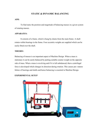
It consists of a frame, which is hung by chains from the main frame. A shaft
rotates within bearings in the frame. Four eccentric weights are supplied which can be
easily fitted over the shaft.
THEORY:
Balancing of masses is an important aspect of Machine Design. When a mass is
stationary it can be easily balanced by putting suitable counter weight on the opposite
side of mass. When a mass is revolving and if it is left unbalanced, then a centrifugal
force is developed which changes its direction during rotation. This causes pre- mature
failure of bearings and shafts and hence balancing is essential in Machine Design.
EXPERIMENTAL SETUP
2. PROCEDURE:
Static balancing:-
Remove the leather rope over the pulley.
Fix the pointer to 0° position.
Attach the balancing pans.
Remove locking screw and go on adding steel balls to the pan till, the pointer
rotates through 90o count number of balls. This The weight of balls in the
balancing weight for the eccentric weight similarly, find out relative weight for all
eccentric weights and note down.
Dynamic balancing:-
From the relative weight (number of balls) assume position of two of the weights
over shaft, draw the force polygon and find out position of other weights.
Mount the weights at proper position over the shaft.
Put the leather belt over the pulley and start the motor.
If the system is balanced, the shaft will rotate free from vibrations.
Calculations:
1) Static balancing: -
Let the given weights be m1r1 and m2r2 with an angle between them be 0,
m3r3 and m4r4 are the balancing weights whose angular position are to be determined.
Draw positions of m1r1 and m2r2 in position diagram. To draw force polygon (Fig.b.)
draw ‘ab’ parallel to min to some scale From ‘a’, draw an arc whose radius is
proportional to m4r4 and from ‘c’ draw an arc with radius proportional to m3r3 The
intersection of the arc gives point ‘d.’ Join ‘ad’ and ‘cd’ draw parallel lines to ‘cd’ and ab
in position diagram, this will give angular position of m3r3 and m4r4 respectively.
3. 2) Dynamic balancing: -
Follow the procedure for static balancing of the system and find out
angular position of balance weights. To find the linear position couple polygon (Fig.d.) is
required, assume linear position of m1r1 taking moments about rotating plane of m3r3
couples are 1) m1r1x, 2) m2r2a2, 3) m4r4a1
Draw ‘ab’ parallel to m1r1 to the scale of m1r1 couple. From ‘b’ draw
parallel to m2r2 from ‘a’ draw parallel line to m4r4 The intersection gives point ‘c’ “bo” is
proportional to m2r2a2 and “ac” is proportional to m4r4a1. As m2r2 and m4r4 are known
values then a. & a2 can be determined.
Calculation:
m1 = gr
m2 = gr
m3 = gr
m4 = gr
r1 = cm
r2 = cm
r3 = cm
r4 = cm