
Recommended
More Related Content
What's hot
What's hot (20)
Similar to BALANCING OF RECIPROCATING MASSES.ppt
Similar to BALANCING OF RECIPROCATING MASSES.ppt (20)
More from karthik R
More from karthik R (17)
Recently uploaded
Recently uploaded (20)
BALANCING OF RECIPROCATING MASSES.ppt
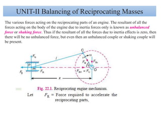
- 1. UNIT-II Balancing of Reciprocating Masses The various forces acting on the reciprocating parts of an engine. The resultant of all the forces acting on the body of the engine due to inertia forces only is known as unbalanced force or shaking force. Thus if the resultant of all the forces due to inertia effects is zero, then there will be no unbalanced force, but even then an unbalanced couple or shaking couple will be present.
- 2. Since FR and FI are equal in magnitude but opposite in direction, therefore they balance each other. The horizontal component of FB (i.e. FBH) acting along the line of reciprocation is also equal and opposite to FI. This force FBH = FU is an unbalanced force or shaking force and required to be properly balanced. The force on the sides of the cylinder walls (FN) and the vertical component of FB (i.e. FBV) are equal and opposite and thus form a shaking couple of magnitude FN × x or FBV × x. From above we see that the effect of the reciprocating parts is to produce a shaking force and a shaking couple. Since the shaking force and a shaking couple vary in magnitude and direction during the engine cycle, therefore they cause very objectionable vibrations. Thus the purpose of balancing the reciprocating masses is to eliminate the shaking force and a shaking couple. In most of the mechanisms, we can reduce the shaking force and a shaking couple by adding appropriate balancing mass, but it is usually not practical to eliminate them completely. In other words, the reciprocating masses are only partially balanced.
- 5. 3. From above we see that secondary unbalanced force is 1/n times the maximum primary unbalanced force. 4. In case of moderate speeds, the secondary unbalanced force is so small that it may be neglected as compared to primary unbalanced force. 5. The unbalanced force due to reciprocating masses varies in magnitude but constant in direction while due to the revolving masses, the unbalanced force is constant in magnitude but varies in direction. Partial Balancing of Unbalanced Primary Force in a Reciprocating Engine
- 6. Partial Balancing of Locomotives The locomotives, usually, have two cylinders with cranks placed at right angles to each other in order to have uniformity in turning moment diagram. The two cylinder locomotives may be classified as : 1. Inside cylinder locomotives ; and 2. Outside cylinder locomotives. In the inside cylinder locomotives, the two cylinders are placed in between the planes of two driving wheels as shown in Fig. 22.3 (a) ; whereas in the outside cylinder locomotives, the two cylinders are placed outside the driving wheels, one on each side of the driving wheel, as shown in Fig. 22.3 (b). The locomotives may be
- 7. A single or uncoupled locomotive is one, in which the effort is transmitted to one pair of the wheels only ; whereas in coupled locomotives, the driving wheels are connected to the leading and trailing wheel by an outside coupling rod. Effect of Partial Balancing of Reciprocating Parts of Two Cylinder Locomotives Due to this partial balancing of the reciprocating parts, there is an unbalanced primary force along the line of stroke and also an unbalanced primary force perpendicular to the line of stroke. The effect of an unbalanced primary force along the line of stroke is to produce; 1. Variation in tractive force along the line of stroke ; and 2. Swaying couple. The effect of an unbalanced primary force perpendicular to the line of stroke is to produce variation in pressure on the rails, which results in hammering action on the rails. The maximum magnitude of the unbalanced force along the perpendicular to the line of stroke is known as a hammer blow. We shall now discuss the effects of an unbalanced primary force in the following articles. Variation of Tractive Force The resultant unbalanced force due to the two cylinders, along the line of stroke, is known as tractive force.
- 8. Maximum and minimum value of the tractive force or the variation in tractive force Swaying Couple The unbalanced forces along the line of stroke for the two cylinders constitute a couple about the centre line YY between the cylinders as shown in Fig. 22.5. This couple has swaying effect about a vertical axis, and tends to sway the engine alternately in clockwise and anticlockwise directions. Hence the couple is known as swaying couple. a = Distance between the centre lines of the two cylinders. Maximum and minimum value of the swaying couple
- 9. Hammer Blow We have already discussed that the maximum magnitude of the unbalanced force along the perpendicular to the line of stroke is known as hammer blow. We know that the unbalanced force along the perpendicular to the line of stroke due to the balancing mass B, at a radius b, in order to balance reciprocating parts only is B. 2.b sin . This force will be maximum when sin is unity, i.e. when = 90° or 270°. Hammer blow = B.2.b The effect of hammer blow is to cause the variation in pressure between the wheel and the rail. Net pressure between the wheel and the rail = P B.2.b If (P–B.2.b) is negative, then the wheel will be lifted from the rails. Therefore the limiting condition in order that the wheel does not lift from the rails is given by P= B.2.b
- 10. An inside cylinder locomotive has its cylinder centre lines 0.7 m apart and has a stroke of 0.6 m. The rotating masses per cylinder are equivalent to 150 kg at the crank pin, and the reciprocating masses per cylinder to 180 kg. The wheel centre lines are 1.5 m apart. The cranks are at right angles. The whole of the rotating and 2/3 of the reciprocating masses are to be balanced by masses placed at a radius of 0.6 m. Find the magnitude and direction of the balancing masses. Find the fluctuation in rail pressure under one wheel, variation of tractive effort and the magnitude of swaying couple at a crank speed of 300 r.p.m. Solution. Given : a = 0.7 m; lB = lC = 0.6 m or rB = rC = 0.3 m; m1 = 150 kg; m2 = 180 kg; c = 2/3; rA = rD = 0.6 m; N = 300 r.p.m. or = 2 x π x300 / 60 = 31.42 rad/s We know that the equivalent mass of the rotating parts to be balanced per cylinder at the crank pin, m = mB = mC = m1 + c.m2
- 11. Magnitude and direction of the balancing masses 0.9 mD = vector c’o’ = 94.5 kg-m2 or mD = 105 kg D = 250°
- 13. 0.6 mA = vector do = 63 kg-m or mA = 105 kg A = 200°
- 14. Fluctuation in rail pressure
- 15. The following data apply to an outside cylinder uncoupled locomotive : Mass of rotating parts per cylinder = 360 kg ; Mass of reciprocating parts per cylinder = 300 kg ; Angle between cranks = 90° ; Crank radius = 0.3 m ; Cylinder centres = 1.75 m ; Radius of balance masses = 0.75 m ; Wheel centres = 1.45 m. If whole of the rotating and two-thirds of reciprocating parts are to be balanced in planes of the driving wheels, find : 1. Magnitude and angular positions of balance masses, 2. Speed in kilometres per hour at which the wheel will lift off the rails when the load on each driving wheel is 30 kN and the diameter of tread of driving wheels is 1.8 m, and 3. Swaying couple at speed arrived at in (2) above. Solution : Given : m1 = 360 kg ; m2 = 300 kg ; AOD = 90° ; rA = rD = 0.3 m ; a = 1.75 m ; rB = rC = 0.75 m ; c = 2 / 3. m = mA = mD = m1 + c.m2 =
- 16. 1. Magnitude and angular position of balance masses
- 17. 1.08 mC = 269.6 kg-m2 or mC = 249 kg C = 275°
- 18. 0.75 mB = 186.75 kg-m or mB = 249 kg Ans. B = 174.5°
- 20. Balancing of Primary Forces of Multi-cylinder In-line Engines A five cylinder in-line engine running at 750 r.p.m. has successive cranks 144° apart, the distance between the cylinder centre lines being 375 mm. The piston stroke is 225 mm and the ratio of the connecting rod to the crank is 4. Examine the engine for balance of primary and secondary forces and couples. Find the maximum values of these and the position of the central crank at which these maximum values occur. The reciprocating mass for each cylinder is 15 kg.
- 24. Maximum unbalanced primary couple gives the maximum unbalanced primary couple. By measurement, we find that maximum unbalanced primary couple is proportional to 1.62 kg-m2. Maximum unbalanced primary couple, U.P.C. = 1.62 × ω2 = 1.62 (78.55)2 = 9996 N-m Ans. Maximum unbalanced secondary couple Maximum unbalanced secondary couple gives the maximum unbalanced secondary couple. By measurement, we find that maximum unbalanced secondary couple is proportional to 2.7 kg-m2 Therefore, the maximum unbalanced secondary couple occurs when crank 3 is at 45° and at successive intervals of 90° (i.e. 135°, 225° and 315°) from the line of stroke.