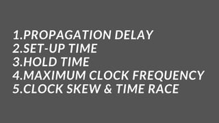
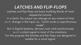
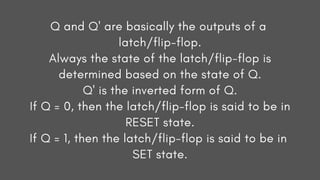
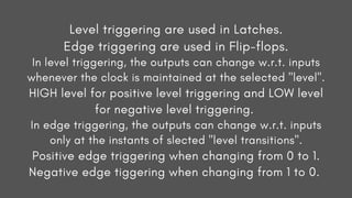
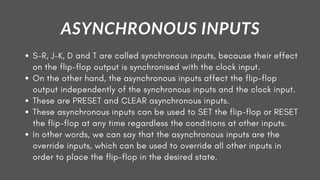
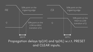
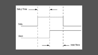
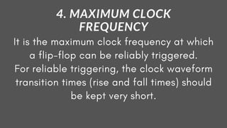
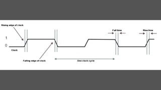
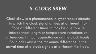
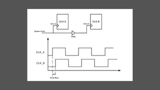
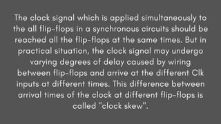
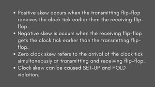
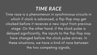
OPERATING CHARACTERISTICS
OF A FLIP-FLOP
1.PROPAGATION DELAY
2.SET-UP TIME
3.HOLD TIME
4.MAXIMUM CLOCK FREQUENCY
5.CLOCK SKEW & TIME RACE
Latches and flip-flops are basic building blocks of most
sequential circuits.
In a latch, the output can change at any instant of time
w.r.t. change in the input i.e., "Latch works in asynchronous
mode".
But in Digital Systems, devices must work synchronously
w.r.t. a clock signal in most of the situations.
For this purpose the latches and flip-flops are designed to
enable for a clock signal.
LATCHES AND FLIP-FLOPS
Q and Q' are basically the outputs of a
latch/flip-flop.
Always the state of the latch/flip-flop is
determined based on the state of Q.
Q' is the inverted form of Q.
If Q = 0, then the latch/flip-flop is said to be in
RESET state.
If Q = 1, then the latch/flip-flop is said to be in
SET state.
Level triggering are used in Latches.
Edge triggering are used in Flip-flops.
In level triggering, the outputs can change w.r.t. inputs
whenever the clock is maintained at the selected "level".
HIGH level for positive level triggering and LOW level
for negative level triggering.
In edge triggering, the outputs can change w.r.t. inputs
only at the instants of slected "level transitions".
Positive edge triggering when changing from 0 to 1.
Negative edge tiggering when changing from 1 to 0.
The output of a flip-flop will not change state
immediately after the application of the clock
signal or asynchronous inputs. The time interval
between the time of application of the triggering
edge or asynchronous inputs and the time at which
the output actually makes a transition is called the
"propagation delay time of the flip-flop".
1. PROPAGATION DELAY
S-R, J-K, D and T are called synchronous inputs, because their effect
on the flip-flop output is synchronised with the clock input.
On the other hand, the asynchronous inputs affect the flip-flop
output independently of the synchronous inputs and the clock input.
These are PRESET and CLEAR asynchronous inputs.
These asynchronous inputs can be used to SET the flip-flop or RESET
the flip-flop at any time regardless the conditions at other inputs.
In other words, we can say that the asynchronous inputs are the
override inputs, which can be used to override all other inputs in
order to place the flip-flop in the desired state.
ASYNCHRONOUS INPUTS
Active-High Asynchronous Inputs
D Flip-Flop
D Q
Q
Q'
Q'
Clk
Clk
Cr
Pr
x
Y
Clk
Clk
tp(LH) tp(HL)
Q Q
Clk
Propagation delays tp(LH) and tp(HL) w.r.t. Clk
50% point on the
trigeering edge
50% point on the
LOW-to-HIGH
transition of Q
50% point on the
HIGH-to-LOW
transition of Q
50% point on the
trigeering edge
PRE
Q Q
CLR
50% point on the
trigeering edge
50% point on the
trigeering edge
50% point on the
LOW-to-HIGH
transition of Q
50% point on the
HIGH-to-LOW
transition of Q
Propagation delays tp(LH) and tp(HL) w.r.t. PRESET
and CLEAR inputs.
tp(LH) tp(HL)
It is the minimum time for which the control
signals need to be maintained constant on
the input terminals of the flip-flop, prior to
the arrival of the triggering edge of the
clock pulse, in order to enable the flip-flop
to respond for the input reliably.
2. SET-UP TIME
It is the minimum time for which the control
signals need to be maintained constant on
the input terminals of the flip-flop, after
the arrival of the triggering edge of the
clock pulse, in order to enable the flip-flop
to respond for the input reliably.
3. HOLD TIME
It is the maximum clock frequency at which
a flip-flop can be reliably triggered.
For reliable triggering, the clock waveform
transition times (rise and fall times) should
be kept very short.
4. MAXIMUM CLOCK
FREQUENCY
Clock skew is a phenomenon in synchronous circuits
in which the clock signal arrives at different flip-
flops at different times. It may be due to wire
interconnect length or temperature variations or
differences in input capacitance on the clock inputs.
So, clock skew is the maximum difference in the
arrival time of a clock signals at different flip-flops.
5. CLOCK SKEW
The clock signal which is applied simultaneously to
the all flip-flops in a synchronous circuits should be
reached all the flip-flops at the same times. But in
practical situation, the clock signal may undergo
varying degrees of delay caused by wiring
between flip-flops and arrive at the different Clk
inputs at different times. This difference between
arrival times of the clock at different flip-flops is
called "clock skew".
Positive skew occurs when the transmitting flip-flop
receives the clock tick earlier than the receiving flip-
flop.
Negative skew is occurs when the receiving flip-flop
gets the clock tick earlier than the transmitting flip-
flop.
Zero clock skew refers to the arrival of the clock tick
simultaneously at transmitting and receiving flip-flop.
Clock skew can be caused SET-UP and HOLD
violation.
Time race is a phenomenon in synchronous circuits in
which if clock is advanced, a flip-flop may get
clocked before it receives a new input from previous
stage. On the other hand, if the clock pulse is
delayed significantly, the inputs to the flip-flop may
have changed before the clock pulse arrives. In
these situations, we have a kind of race between
the two competing signals.
TIME RACE

Static Timing Analysis Fundamentals Part-1

  • 1.
  • 2.
    1.PROPAGATION DELAY 2.SET-UP TIME 3.HOLDTIME 4.MAXIMUM CLOCK FREQUENCY 5.CLOCK SKEW & TIME RACE
  • 3.
    Latches and flip-flopsare basic building blocks of most sequential circuits. In a latch, the output can change at any instant of time w.r.t. change in the input i.e., "Latch works in asynchronous mode". But in Digital Systems, devices must work synchronously w.r.t. a clock signal in most of the situations. For this purpose the latches and flip-flops are designed to enable for a clock signal. LATCHES AND FLIP-FLOPS
  • 4.
    Q and Q'are basically the outputs of a latch/flip-flop. Always the state of the latch/flip-flop is determined based on the state of Q. Q' is the inverted form of Q. If Q = 0, then the latch/flip-flop is said to be in RESET state. If Q = 1, then the latch/flip-flop is said to be in SET state.
  • 5.
    Level triggering areused in Latches. Edge triggering are used in Flip-flops. In level triggering, the outputs can change w.r.t. inputs whenever the clock is maintained at the selected "level". HIGH level for positive level triggering and LOW level for negative level triggering. In edge triggering, the outputs can change w.r.t. inputs only at the instants of slected "level transitions". Positive edge triggering when changing from 0 to 1. Negative edge tiggering when changing from 1 to 0.
  • 6.
    The output ofa flip-flop will not change state immediately after the application of the clock signal or asynchronous inputs. The time interval between the time of application of the triggering edge or asynchronous inputs and the time at which the output actually makes a transition is called the "propagation delay time of the flip-flop". 1. PROPAGATION DELAY
  • 7.
    S-R, J-K, Dand T are called synchronous inputs, because their effect on the flip-flop output is synchronised with the clock input. On the other hand, the asynchronous inputs affect the flip-flop output independently of the synchronous inputs and the clock input. These are PRESET and CLEAR asynchronous inputs. These asynchronous inputs can be used to SET the flip-flop or RESET the flip-flop at any time regardless the conditions at other inputs. In other words, we can say that the asynchronous inputs are the override inputs, which can be used to override all other inputs in order to place the flip-flop in the desired state. ASYNCHRONOUS INPUTS
  • 8.
    Active-High Asynchronous Inputs DFlip-Flop D Q Q Q' Q' Clk Clk Cr Pr x Y
  • 9.
    Clk Clk tp(LH) tp(HL) Q Q Clk Propagationdelays tp(LH) and tp(HL) w.r.t. Clk 50% point on the trigeering edge 50% point on the LOW-to-HIGH transition of Q 50% point on the HIGH-to-LOW transition of Q 50% point on the trigeering edge
  • 10.
    PRE Q Q CLR 50% pointon the trigeering edge 50% point on the trigeering edge 50% point on the LOW-to-HIGH transition of Q 50% point on the HIGH-to-LOW transition of Q Propagation delays tp(LH) and tp(HL) w.r.t. PRESET and CLEAR inputs. tp(LH) tp(HL)
  • 11.
    It is theminimum time for which the control signals need to be maintained constant on the input terminals of the flip-flop, prior to the arrival of the triggering edge of the clock pulse, in order to enable the flip-flop to respond for the input reliably. 2. SET-UP TIME
  • 12.
    It is theminimum time for which the control signals need to be maintained constant on the input terminals of the flip-flop, after the arrival of the triggering edge of the clock pulse, in order to enable the flip-flop to respond for the input reliably. 3. HOLD TIME
  • 14.
    It is themaximum clock frequency at which a flip-flop can be reliably triggered. For reliable triggering, the clock waveform transition times (rise and fall times) should be kept very short. 4. MAXIMUM CLOCK FREQUENCY
  • 16.
    Clock skew isa phenomenon in synchronous circuits in which the clock signal arrives at different flip- flops at different times. It may be due to wire interconnect length or temperature variations or differences in input capacitance on the clock inputs. So, clock skew is the maximum difference in the arrival time of a clock signals at different flip-flops. 5. CLOCK SKEW
  • 18.
    The clock signalwhich is applied simultaneously to the all flip-flops in a synchronous circuits should be reached all the flip-flops at the same times. But in practical situation, the clock signal may undergo varying degrees of delay caused by wiring between flip-flops and arrive at the different Clk inputs at different times. This difference between arrival times of the clock at different flip-flops is called "clock skew".
  • 19.
    Positive skew occurswhen the transmitting flip-flop receives the clock tick earlier than the receiving flip- flop. Negative skew is occurs when the receiving flip-flop gets the clock tick earlier than the transmitting flip- flop. Zero clock skew refers to the arrival of the clock tick simultaneously at transmitting and receiving flip-flop. Clock skew can be caused SET-UP and HOLD violation.
  • 20.
    Time race isa phenomenon in synchronous circuits in which if clock is advanced, a flip-flop may get clocked before it receives a new input from previous stage. On the other hand, if the clock pulse is delayed significantly, the inputs to the flip-flop may have changed before the clock pulse arrives. In these situations, we have a kind of race between the two competing signals. TIME RACE