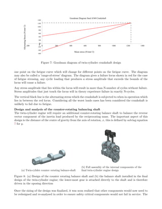
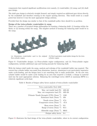
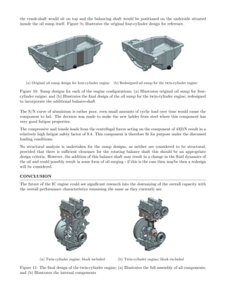
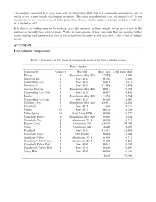
DAVID JOHN STANSFIELD
Twin cylinder engine design with a rotating balance saft
19 Rowan Drive, Chepstow, Monmouthshire, NP16 5RR, UK
Stansfield.DavidJohn@gmail.com
(+44) 7825 580119
ABSTRACT
The internal combustion engine was invented in 1862 by German invertor Nikolaus Otto, since then the
reciprocating combustion engine has advanced and has been developed to this point we have today. The
designs of the modern-day combustion engines have to meet strict Euro-emissions laws to help in order
to better protect the environment in which we live. This results in lower CO2 and NOx emissions and an
improved fuel economy without the reduction in powertrain outputs of performance. As fuel prices continue
to rise car manufacturers are forced to design their vehicles and more importantly their engine technologies
to suit the ever changing market requirements, costs and legislation. The FIAT motor company were
the first to supply a twin-cylinder engine for the current automotive market and have proved to be very
successful with their powertrain technologies and decisions. With high demands on fuel resources, engine
downsizing is one approach that will help meet the needs for the future combustion engines.
(a) Original four-cylinder engine (b) Downsized twin-cylinder engine
Figure 1: Two engines discussed herein; (a) Illustrates the original four-cylinder enigne; and (b) Illustrates
the final design of the downsized twin-cylinder engine.
INTRODUCTION
This document provides an overview of the approach used in engine downsizing, and also discusses the
implications this may have on the design of various components. The original four-cylinder design is based
on the Ford Eco-boost inline 1600cc engine; whereby the author has full access to the complete engine with
full permission to dismantle and reverse engineer any components required.
The main aim is to downsize this 1600cc four cylinder enigne to an 800cc engine whilst maintaining
similar fatigue factors of safety for all critical components. The new downsized engine will also require an
additional balancing shaft in order to counteract the now unblanaced first order forces generated from the
reciprocating mass of the piston and connecting rod assemly.
All computer aided design (CAD), computer aided engineering (CAE) and finite element analysis (FEA)
will be completed within Unigraphics UGS NX-8. This tool offers the ability for a design engineer to
draw/sketch and model components to gain critical information and also include the analysis to aid the
design process.
The design of the current four-cylinder Ford enigne makes it an ideal candidate for this downsizing project.
If we compare it directly to FIAT’s twin-air design, it is evident that similar aspects such as the direct fuel
injection, variable valve timing and the capability of turbo-charging, we see that the Fords Eco-boost can
quite easily be used as the reference model of a new twin-cylinder engine. The new twin cylinder for future
vehicles can be paired with turbo-hybrid technologies which would further see a reduction of up to 35% in
fuel consumption - although this may add additional mass these figures are essentially academic.
DESIGN OF THE FOUR-CYLINDER ENGINE
In order to design a twin-cylinder engine to the specifications of current engine designs, it was necessary
to reverse-engineer the current Force Eco-boost engine accurately and via analytical analysis as well as
numerical FEA it was possible to define a design fatigue safety factor for each of the critical components.
These design fatigue safety factors are then be used to redesign the components for the twin-cylinder engine
components.
Figure 2: Full CAD model of the Ford Eco-boost 1600cc enging
Figure 2 illustrates the reverse-engineering of the Ford Eco-boost engine, it was necessary for this to be
completed with the highest degree of accuracy in order to ensure any validation was correct to the best of
the authors knowledge.
BALANCING THE ROTATING AND RECIPROCATING VECTORS
Balancing the rotating mass
When a mass M attached at a radius r to a shaft, is rotated with an angular velocity ω, there exists an
outward radial force of Mrω2. This produces a bending moment in the shaft. In order to counteract the
effect of this interia force, a balance weight may be introduced into the plane of rotation of the original
mass, such that the interia forces of the two masses equal.
With respect to the rotation of the crankshaft, for every degree of crank rotation θ, the vertical acceleration
is defined as follows,
d2s
dt2
= rω2
cos θ +
r2
l
ω2
cos 2θ + O(r3
) (1)
where the higher order terms can be ignored, as the first and second orders provide sufficient approximation
to the vertical acceleration, however it is also acceptable to negate this second order force as this occur
at twice engine speed and therefore prove more of a challenge to counteract here without the inclusion of
addition unnecessary mass. Therefore, the vertical intertia load, Prot
vert (the load applied to the connecting
rod and crankshaft due to the rotating mass of the system) can therefore be approximated as follows,
Prot
vert = Mrot
d2s
dt2
= Mrot rω2
cos θ (2)
where Mrot is the total rotating mass, r is the crankthrow radius.
Balancing the forward reciprocating mass
The reciprocating forces are also an important aspect of any internal combustion (IC) engine, these are
defined in a similar manner as the rotating inertia forces, however in this instance we assume a forward
and a reverse rotating vector. This is essentially because the point of rotation of the crank is inline with
the point of rotation about the gudgen-pin, for equilibrium to exist the forces must therefore act directly
along the central plane. For the problem to be solved it must be assumed that the system is in equilibrium
at all angles. The only way this is possible is for a second reverse vector to exists of the same magnitude
as that of the forward vector acting in the −θ direction.
The component of the vertical inertia load due to the forward rotating vector, Pf
vert, is defined as fol-
lows,
Pf
vert =
1
2
Mrec rω2
cos θ (3)
where Mrec is the mass-fraction of the total mass assumed to be reciprocating rather than rotating about
the crank axis.
Balancing the reverse reciprocating mass
As previously explained, the reverse reciprocating vectors are identical in magnitude to the forward re-
ciprocating vectors, however they act at an angle −θ, i.e. rotate in the oposite direction, therefore, the
component of the vertical inertia load due to the reverse rotating vector, Pr
vert, is defined as follows,
Pr
vert =
1
2
Mrec rω2
cos θ (4)
it is evident from equations 3 and 4 that Pf
vert and Pr
vert are identical to one another. The only difference
between the two is their direction, whereby at top dead centre (TDC), i.e. θ = 0, they both act vertically
upwards, and at bottom dead centre (BDC), i.e. θ = 180 they both act vertically downwards.
Therefore at TDC the total component of the vertical interia load due to the reciprocating mass is,
Prec
vert
TDC
= Pf
vert + Pr
vert =
1
2
Mrec rω2
cos θ +
1
2
Mrec rω2
cos θ = Mrec rω2
cos θ (5)
Summary of rotating and reciprocating forces
In order to use the procedure explained above in the design of a two cylinder engine, it is necessary to
explain what aspects are important. The first order rotating mass and the first order forward reciprocating
mass can be combined as they act along the same vector at all values of θ. It is therefore possible to balance
these exactly by designing the crankweb or more importantly the CofG of the crankweb accordingly.
Therefore, the equation used to design the crankshaft in the twin-cylinder design is as follows,
Mcsxω2
= Mrot rω2
cos θ +
1
2
Mrec rω2
cos θ (6)
which incidentally would be identical to that used in the design of the four-cylinder configuration. Where
Mcs is the total mass of the entire crank-span (for a single cylinder), and x relates to the distance of the
centre of mass from the axis or rotation.
Yet, for a four-cylinder engine, the reverse rotating vectors are balanced exactly at all times due to the
opposing crank journals (for both the in-plane and the cross-plane configurations) design; this is not
necessarily the case for a twin-cylinder design. It is possible to balance these forces in a twin-cylinder
using the crank alone, however that would require a crankshaft with journals that are opposed to one
another by 180◦. This configuration would create an uneven firing order and therefore a particularly
uncomfortable driving experience for the end user. It is therefore more appropriate to design a twin-
cylinder with in-line crank journals, where both are orientated in the same direction. This is therefore the
design configuration utilized in this project.
The approach used to balance the reverse rotating vector (due to the reciprocating mass) is to incorporate
some form of counter-rotating balance-shaft. This will be designed following a similar philosphy used in
the balancing of the forward rotating vector, such that,
Mbsyω2
=
1
2
Mrecrω2
(7)
where Mbs is the mass of counter rotating balance shaft, and y is the distance of its centre of mass from
the axis of rotation.
-8000
-6000
-4000
-2000
0
2000
4000
6000
8000
10000
-400 -300 -200 -100 0 100 200 300 400
InertiaForce(N)
Crank Angle (Theta)
Crank Angle Against Vertical Inertia Forces
1st Order Inertia Forces
2nd Order Inertia Forces
Total Inertia forces
Figure 3: Change in forces generated by inertia loads of rotating and reciprocating masses varying though
angle of rotation at maximum angular velocity equivalent to 6000RPM
Figure 3 illustrates the combined effect of the first and second order inertia forces experienced, however
what this figure does not present is the additional loading experienced during the combustion stroke of the
Otto cycle. During combustion, although the inertia loads will remain the same, an additional pressure
load is observed at TDC which will counteract a proportion of the inertia load, and therefore reduce the
tensile axial stress sustained in the connecting rod and other internal components.
DETERMINATION OF FATIGUE SAFETY FACTORS
As previously mentioned, in order to obtain design the components for the twin-cylinder engine, we first
must establish the fatigue safety factors that govern the design. In an industrial setting, these figures
are generally defined empirically or are pre-defined and simply read from an internal company standard.
However, as the author has limited access to this information it was deemed more appropriate to reverse-
engineer the current components in order to determine these design fatigue safety factors. The method by
which this was achieved will be discussed within this section.
Based on the Goodman mean stress equation for fatigue failure,
σa
σN
+
σm
σu
= 1 (8)
where σa , σN , σm and σu correspond to the amplitude stress, endurance limit, mean stress and ultimate
material strength, respectively. Therefore the design fatigue safety factor is defined such that,
SFf =
σA
σM
= σN 1 −
σm
σu
=
Allowable stress range
Actual stress range
(9)
σA =
σu − σN
σu
σa
2
+ σN −
σu + σN
σu
σa
2
− σN (10)
From equations 9 and 10 it is possible in conjunction with FEA to reverse engineer, with relative confidence,
each of the components of the four-cylinder engine.
ANALYSIS OF THE CONNECTING ROD
The connecting rod is the only component that could theoretically remain the same for both the four-
and the twin-cylinder engine. Provided that the engine speeds are equivalent, and the pistons remain the
same between the two configurations, then the loads sustained will also be identical; these are outlined in
equations 3 and 4. It seems only logical to analyse each of these components at a worst-case scenario, thus
at the highest load, this corresponds to an angular velocity, ω, equivalent to 6000RPM during an exhaust
cycle, i.e. without any compressive load due to combustion (as this acts in the oposing direction to the
inertia loads and would therefore reduce the risk of failre). Therefore, the most critical load is determined
as follows,
Pmax
vert
conrod
TDC
= Prec
vert = Mrec rω2
cos θ (11)
where Mrec will vary along the length of the connecting rod, such that the conecting rod will be analysed
at specific locations that are deemed critical, the finite value of Mrec will be determined from the CAD
model;
Mrec
conrod
= Mpiston + Mgudgeon + Mconrod (12)
where Mpiston and Mgudgeon are the respective masses of the piston and the gudgeon pin, which do not
change regardless of the point of interest on the connecting rod, however Mconrod is the mass-fraction of the
connecting rod above the point of interest - which is the finite mass determined from the CAD model.
In order to improve the performance of the engine, in terms of the acceleration of the enigne but also in
terms of the reduction of mass and therefore an increase in efficiency, it was suggested that an alternative
material could be used. The chosen material was Titanium (Ti-6Al-4V), and when compared directly to
the steel equivalent, it is evident (see table 1) that the fatigue safety factor is increased for the titanium
connecting rod.
Although, for a commercial application the increase in cost over a production range would be significant
and therefore an unlikely design choice, for the purpose of this academic project it is simply interesting to
note the difference.
Table 1 outlines the results of both the conventional steel connecting rod directly compared to the titanium
equivalent. The fatigue safety factor increases by 42% when switching from steel to titanium, it is also
worth noting that the deflection at maximum load also increases proportionally with the change in the
modulus of elasticity.
Table 1: Analysis of connecting rod; a comparison of results between a steel and titanium connecting rods
of equivalent geometry
Conrod Steel 4340 Conrod Titanium
Max. net tensile load (N) 12013.85 12013.85
Max. net compressive load (N) 36909.87 36909.87
Ultimate Tensile Strength (UTS) (Nmm−2) 1240 845
Endurance limit (Nmm−2) 450 624
Tensile stress (Nmm−2) 103.6 103.6
Compressive stress (Nmm−2) -310.7 -310.7
Mean stress (Nmm−2) -103.6 -103.6
Range of stress (Nmm−2) 414.3 414.3
Allowable range (Nmm−2) 975.2 1401.0
Fatigue safety factor 2.4 3.4
The increase in the factor of safety is solely due to the fact that the density of titanium is much less than
that of steel, therefore for similar geometry the component is proportionally lighter. This reduction in
mass, from 0.494kg to 0.278kg, reduces the overall reciprocating mass by as much as 12%; but once more
note that this is not always a positive result, as the net-downforce on the conrod will have increased due
to the greater offset on a combustion stroke.
(a) Maximum principal stress; 400 MPa (b) Axial deformation; maximum 0.22 mm
Figure 4: Finite element analysis of twin cylinder connecting rods; (a)Maximum principal stress; 400 MPa;
(b)Axial deformation; maximum 0.22 mm
Figures 4a and 4b illustrate the graphical results from the FEA of the connecting rod based on the steel
configuration. Although these are relatively pleasing results, it must be noted that the finite element
model (FEM) does not include the effect of the gudgeon pin; if this was included the displacement would
be reduced somewhat.
DESIGN OF THE TWIN-CYLINDER ENGINE
An engine is essentially a vibrating machine, the vibrations encountered can sometimes be severe. It is
essential for the comfort of the end user that these vibrations are reduced as much as possible. The manner
in which this is achieved is simply by balancing them with counterweights. The source of these vibration
forces are from the combustion and exhaust strokes within each cylinder, whereby these forces are all
reacted at the crankshaft.
In four-cylinder engines, the reverse rotating vectors are perfectly balanced due to the oposing crank-
journal configuration. However in the twin-cylinder engine these reverse are not necessarily balanced; for
a 180◦ twin-cylinder crank the firing order is odd, i.e. would not feel or sound very smooth; whereas a
360◦ twin-cylinder crank is even and therefore much smoother. This configuration is far more appropriate
to a smaller car; however it has additional problems such that the reverse rotating vectors are no longer
naturally balanced by the crankshaft counter-weights. To balance these forces requires a counter-rotating
balance shaft.
There are a wide range of components that need to be considered when downsizing the four cylinder
engine to the twin-cylinder format; and a number of different criteria can be use to warrant the analysis,
i.e. packaging and manufacturing constraints should always be considered, however these lay outside the
remit of the current project. Instead, the critical structural components from the four-cylinder engine
will be reverse-engineerd in order to define the fatigue safety factors, thus be used as a reference for the
twin-cylinder component design.
The critical components analysed are, namely, (i) piston; (ii) connecting rods (both in steel and titanium);
(iii) crankshaft; (iv) crank ladder; (v) balance shaft.
Determination of vertical inertia loads
The crankshaft is the most important component within any IC engine, the loads it sustains are significant
and the structural vibrations observed propogate from this component. It is therefore rather important
that this component is accurately designed. There are two main areas of concern when discussing the
crankshaft, namely (i) balancing; and (ii) cyclic loading.
The maximum load acting on each of the crank-journals is once again determined at TDC during the
exhust stroke, in this instance the entire mass of the connecting rod is incorporated in the calculation,
however a mass fraction is used to define how much of the mass of the connecting rod is assumed to rotate
and how much is assumed to reciprocate.
The conventional mass-fraction used in this particular Force Eco-boost engine is 1:2, such that
Pmax
vert
crankshaft
TDC
= Prot
vert + Prec
vert = Mrot rω2
cos θ +
1
2
Mrec rω2
cos θ
= Mrot rω2
+
1
2
Mrec rω2
(13)
where,
Mrot =
2
3
Mconrod + Mcap + Mbolts
Mrec =
1
3
Mconrod + Mpiston + Mgudgeon
(14)
where, Mcap and Mbolts are the respective masses of the big-end connecting rod cap and the bolts that
couple this to the crankshaft.
For the four-cylinder engine balancing for equations 13 and 14 results in a perfecty balanced system,
however these alone are insufficient for a twin-cylinder engine due to the additional unbalanced reverse
rotating vector. This reverse vector is balanced by solving for y in equation 7.
Design of the twin-cylinder crankshaft
As mentioned, the first stage in the design process for the twin-cylinder crankshaft was to balance the
structure; this was relatively straight forward for the forward vector component of the force due to the
reciprocating masses as well as the rotating masses. These were balanced directly by the crank-webs,
initially the design was underbalanced (see figure 6a) and required additional mass in terms of additional
webs (see figure 6b) however this too was deemed insufficient. At this stage of the design process it was
noticed that any additional mass added to these crank-webs would result in a colision with the piston whilst
rotating through BDC; therefore in order to move the CofG, mass was removed rather than added. Mass
was removed from the crank-journal (see figure 6c) in the form of drilled holes, and this final configuration
illustrated in figure 6c is designed to perfectly balance the system with a titanium connecting rod.
Figure 5: Four-cylinder crankshaft design
(a) First iteration (b) Second iteration (c) Final iteration
Figure 6: The design iterations of the twin-cylinder crankshaft design; (a) First basic design similar to
the four cylinder outer crank-journals; (b) Second iteration with the additional crank-webs; and (c) Final
iteration with drilled holes in the journals to shift the centre of mass further from the axis.
Once again, the fatigue safety factor was defined for the four-cylinder engine as it was done so previously,
and this was used as a minimum requirement for the twin-cylinder engine design. Identical material and
thus material properties were used for both designs, table 2 illustrates the results.
Table 2: Steel crankshaft analysis; Four cylinder and twin-cylinder; 4340 steel
Four-cylinder Crankshaft Twin-cylinder Crankshaft
Max. net tensile load (N) 1214 8202
Max. net compressive load (N) 36910 37206
Ultimate Tensile Strength (UTS) (Nmm−2) 1240 1240
Endurance limit (Nmm−2) 450 450
Tensile stress (Nmm−2) 33.3 18.5
Compressive stress (Nmm−2) -108.1 -84.8
Mean stress (Nmm−2) -37.4 -33.2
Range of stress (Nmm−2) 141.4 103.3
Allowable range (Nmm−2) 927.1 924.1
Fatigue safety factor 6.6 8.9
It is clear that from table 2 that the design of the twin-cylinder falls within the design specification defined
for the four-cylinder engine design. On initial inspection the fatigue safety factors seem excessive for
the twin-cylinder, however it is also worth noting that the design would likely incorporate some form of
turbo-charging and therefore this inertia-loading would unlikely be the first mode of failure. In reality the
compressive load sustained from the additional pressure of turbocharging would likely result in a more
compressive failure at BDC.
Figure 7 illustrates the Goodman diagram constructed for the twin-cylinder crankshaft. A Goodman
diagram is constructed for a single fatigue lifetime of N-cycles. The Goodman Diagram is only good for
-600
-400
-200
0
200
400
600
800
1000
1200
1400
-200 0 200 400 600 800 1000 1200 1400
AlternatingStress(N/mm^2)
Mean stress (N/mm^2)
Goodman Diagram Steel 4340 Crankshaft
Figure 7: Goodman diagram of twin-cylinder crankshaft design
one point on the fatigue curve which will change for different points on the fatigue curve. The diagram
may also be called a ’range-of-stress’ diagram. The diagram gives a failure locus shown in red for the case
of fatigue stressing, any cyclic loading that produces a stress amplitude that exceeds the bounds of the
locus will cause a failure.
Any stress amplitude that lies within the locus will result in more than N-number of cycles without failure.
Stress amplitudes that just touch the locus will in theory experience failure in exactly N-cycles.
The vertical black line is the alternating stress which the crankshaft is subjected to when in operation which
lies in between the red locus. Considering all the worst loads cases has been considered the crankshaft is
unlikely to fail due to fatigue.
Design and analysis of the counter-rotating balancing shaft
The twin-cylinder engine will require an additional counter-rotating balance shaft to balance the reverse
vector component of the inertia load produced by the reciprocating mass. The important aspect of this
design is the distance of the centre of gravity from the axis of rotation, x, this is defined by solving equation
7 for y.
(a) Twin-cylider counter rotating balance-shaft
(b) Full assembly of the internal components of the
final twin-cylinder engine design
Figure 8: (a) Design of the counter rotating balance shaft and (b) the balance shaft installed in the final
design of the twin-cylinder engine; the lower-most gear is attached directly to the shaft and is therefore
driven in the oposing direction
Once the sizing of the design was finalized, it was soon realised that other components would now need to
be redesigned and re-analysed in order to ensure safety critical components would not fail in service. The
components that required significant modifications were namely, (i) crank-ladder; (ii) sump; and (iii) shaft
gear design.
The shaft gear design is relatively straight forward, and simply required an additional gear driven directly
by the crankshaft and therefore rotating in the require oposing direction. This would result in a small
power-loss however it was the most appropriate design solution.
Provided that the design was similar to that of the crankshaft pulley there should be no problem.
Design of the twin-cylinder crank-ladder & sump
There are a number of accepted design philosophies for housing a balancing shaft; (i) housing within the
block; or (ii) housing within the sump. The simplest method of housing the balancing shaft would be in
the sump.
(a) Aluminium crank-ladder used in the original
four-cylinder engine
(b) Steel equivalent crank-ladder design for the twin-
cylinder engine
Figure 9: Crank-ladder designs; (a) Four-cylinder engine configuration; and (b) Twin-cylinder engine
configuration, includes additional caps and bearing journals for balancing shaft.
With the balance shaft inside the sump, analysis and redesign of the crankshaft ladder was required. The
current four cylinder ladder was made from aluminium, however, aluminium is not particularly impressive
under cyclic-loading, and the fatigue limit is not something that is easily predictable. As the new twin
cylinder ladder would be under cyclic loading its an area that required a re-think, a change in material
used was the most appropriate solution. Balancing the centrifugal vector 4321N at maximum RPM is a
relatively significant cyclic-load.
Table 3: Results of fatigue safety factor analysis of twin-cylinder crank-ladder
Twin crank-ladder Steel 4340
Max. net tensile load (N) 4321.30
Max. net compressive load (N) 4321.30
Ultimate Tensile Strength (UTS) (Nmm−2) 1240
Endurance limit (Nmm−2) 450
Tensile stress (Nmm−2) 47.8
Compressive stress (Nmm−2) -47.8
Mean stress (Nmm−2) 0.0
Range of stress (Nmm−2) 95.5
Allowable range (Nmm−2) 900.0
Fatigue safety factor 9.4
Figure 9b illustrates the final design of the twin-cylinder crank-ladder, where in its current configuration
the crank-shaft would sit on top and the balancing shaft would be positioned on the underside situated
insude the oil sump itself. Figure 9a illustrates the original four-cylinder design for reference.
(a) Original oil sump design for four-cylinder engine (b) Redesigned oil sump for the twin-cylinder engine
Figure 10: Sump designs for each of the engine configurations; (a) Illustrates original oil sump for four-
cylinder enigne; and (b) Illustrates the final design of the oil sump for the twin-cylinder engine; redesigned
to incorporate the additional balance-shaft
The S/N curve of aluminium is rather poor, even small amounts of cyclic load over time would cause the
component to fail. The decision was made to make the new ladder from steel where this component has
very good fatigue properties.
The compressive and tensile loads from the centrifugal forces acting on the component of 4321N result in a
relatively high fatigue safety factor of 9.4. This component is therefore fit for purpose under the discussed
loading conditions.
No structural analysis is undertaken for the sump designs, as neither are considered to be structural;
provided that there is sufficient clearance for the rotating balance shaft this should be an appropriate
design criteria. However, the addition of this balance shaft may result in a change in the fluid dynamics of
the oil and could possibly result in some form of oil surging - if this is the case then maybe then a redesign
will be considered.
CONCLUSION
The future of the IC engine could see significant research into the downsizing of the overall capacity with
the overall performance characteristics remaining the same as they currently are.
(a) Twin-cylinder engine; block included (b) Twin-cylinder engine; block excluded
Figure 11: The final design of the twin-cylinder engine; (a) Illustrates the full assembly of all components;
and (b) Illustrates the internal components
The analysis presented here goes some way to illustrating that this is a reasonable assumption, and in
reality is not a particularly challenging excercise. The main considerations that the majority of the car
manufacturers are concerned about is the perception of these smaller engines on larger vehicles; would they
be accepted at all?
It is clearly an exiting area to be working in at this moment in time; weight saving as a whole in the
automotive industry has a lot to learn. With the development of new materials that are gaining further
understanding and appreciation such as the composites industry would only add to this trend of weight-
saving.
APPENDIX
Four-cylinder components
Table 4: Summary of the mass of components used in the four cylinder engine
Four cylinder
Component Quantity Material Mass (kg) Total mass (kg)
Piston 4 Aluminium alloy 328 0.3173 1.268
Gudgeon pin 4 Steel 4340 0.105 0.420
Connecting Rod 4 Steel 4340 0.354 1.416
Crankshaft 1 Steel 4340 11.788 11.788
Journal Bearing 8 Aluminium alloy 328 0.011 0.088
Connecting Rod Bolt 8 Steel 4340 0.017 0.136
Ladder 1 Aluminium alloy 328 1.854 1.854
Connecting Rod cap 4 Steel 4340 0.140 0.560
Cylinder Head 1 Aluminium alloy 328 12.961 12.961
Camshaft 2 Steel 4317 1.505 3.010
Valves 16 Steel J775 0.033 0.528
Valve Spring 16 Steel Alloy 6150 0.020 0.320
Camshaft Pulley 2 Aluminium alloy 328 0.816 1.632
Camshaft Cap 8 Aluminium 2014 0.039 0.312
Engine Block 1 Aluminium 322 23.002 23.002
Sump 1 Aluminium 322 3.520 3.520
Flywheel 1 Steel 4340 14.181 14.181
Camshaft Cover 1 ABS Plastic 0.963 0.963
Auxiliary Pulley 1 Aluminium 2014 0.519 0.519
Crankshaft Belt Pulley 1 Aluminium 2014 0.160 0.160
Camshaft Pulley Bolt 2 Steel 4340 0.041 0.082
Crankshaft Pulley Bolt 1 Steel 4340 0.300 0.300
Sump Bolt 1 Steel 4340 0.046 0.046
Total 79.066
Twin-cylinder components
Table 5: Summary of the mass of components used in the twin-cylinder engine
Twin cylinder
Component Quantity Material Mass (kg) Total mass (kg)
Piston 2 Aluminium alloy 328 0.317 0.634
Gudgeon pin 2 Steel 4340 0.105 0.210
Connecting Rod 2 Titanium 6AL 4V 0.199 0.398
Crankshaft 1 Steel 4340 7.507 7.507
Journal Bearing 4 Aluminium alloy 328 0.011 0.044
Connecting Rod Bolt 4 Steel 4340 0.017 0.068
Ladder 1 Steel 4340 3.7673 3.7673
Connecting Rod cap 2 Titanium 6AL 4V 0.079 0.158
Cylinder Head 1 Aluminium alloy 328 7.746 7.746
Camshaft 2 Steel 4317 0.923 1.846
Valves 8 Steel J775 0.033 0.264
Valve Spring 8 Steel Alloy 6150 0.020 0.160
Camshaft Pulley 2 Aluminium alloy 328 0.816 1.632
Camshaft Cap 8 Aluminium 2014 0.039 0.312
Engine Block 1 Aluminium 322 13.553 13.553
Sump 1 Aluminium 322 3.121 3.121
Flywheel 1 Steel 4340 14.181 14.181
Camshaft Cover 1 ABS Plastic 0.609 0.609
Auxiliary Pulley 1 Aluminium 2014 0.519 0.519
Crankshaft Belt Pulley 1 Aluminium 2014 0.160 0.160
Camshaft Pulley Bolt 2 Steel 4340 0.041 0.082
Crankshaft Pulley Bolt 1 Steel 4340 0.300 0.300
Sump Bolt 1 Steel 4340 0.046 0.046
Balancer shaft 1 Steel 4340 1.117 1.117
Gear Crank 1 Steel 4340 0.397 0.397
Gear Balance Shaft 1 Steel 4340 0.404 0.404
Total 59.235
It is evident from a quick comparisson of the masses of individual components presented in Tables 4 and
5 that the redesign of the engine has reduced the overall mass by 25%.
Goodman diagram for twin-cylinder crank-ladder design
-600
-400
-200
0
200
400
600
800
1000
1200
1400
0 200 400 600 800 1000 1200 1400
AlternatingStress(N/mm^2)
Mean stress (N/mm^2)
Goodman Diagram Twin Ladder Steel 4340
Figure 12: Goodman diagram for steel crank-ladder design

Stansfield_DJ_Exhibition

  • 1.
    DAVID JOHN STANSFIELD Twincylinder engine design with a rotating balance saft 19 Rowan Drive, Chepstow, Monmouthshire, NP16 5RR, UK Stansfield.DavidJohn@gmail.com (+44) 7825 580119 ABSTRACT The internal combustion engine was invented in 1862 by German invertor Nikolaus Otto, since then the reciprocating combustion engine has advanced and has been developed to this point we have today. The designs of the modern-day combustion engines have to meet strict Euro-emissions laws to help in order to better protect the environment in which we live. This results in lower CO2 and NOx emissions and an improved fuel economy without the reduction in powertrain outputs of performance. As fuel prices continue to rise car manufacturers are forced to design their vehicles and more importantly their engine technologies to suit the ever changing market requirements, costs and legislation. The FIAT motor company were the first to supply a twin-cylinder engine for the current automotive market and have proved to be very successful with their powertrain technologies and decisions. With high demands on fuel resources, engine downsizing is one approach that will help meet the needs for the future combustion engines. (a) Original four-cylinder engine (b) Downsized twin-cylinder engine Figure 1: Two engines discussed herein; (a) Illustrates the original four-cylinder enigne; and (b) Illustrates the final design of the downsized twin-cylinder engine. INTRODUCTION This document provides an overview of the approach used in engine downsizing, and also discusses the implications this may have on the design of various components. The original four-cylinder design is based on the Ford Eco-boost inline 1600cc engine; whereby the author has full access to the complete engine with full permission to dismantle and reverse engineer any components required. The main aim is to downsize this 1600cc four cylinder enigne to an 800cc engine whilst maintaining similar fatigue factors of safety for all critical components. The new downsized engine will also require an additional balancing shaft in order to counteract the now unblanaced first order forces generated from the reciprocating mass of the piston and connecting rod assemly.
  • 2.
    All computer aideddesign (CAD), computer aided engineering (CAE) and finite element analysis (FEA) will be completed within Unigraphics UGS NX-8. This tool offers the ability for a design engineer to draw/sketch and model components to gain critical information and also include the analysis to aid the design process. The design of the current four-cylinder Ford enigne makes it an ideal candidate for this downsizing project. If we compare it directly to FIAT’s twin-air design, it is evident that similar aspects such as the direct fuel injection, variable valve timing and the capability of turbo-charging, we see that the Fords Eco-boost can quite easily be used as the reference model of a new twin-cylinder engine. The new twin cylinder for future vehicles can be paired with turbo-hybrid technologies which would further see a reduction of up to 35% in fuel consumption - although this may add additional mass these figures are essentially academic. DESIGN OF THE FOUR-CYLINDER ENGINE In order to design a twin-cylinder engine to the specifications of current engine designs, it was necessary to reverse-engineer the current Force Eco-boost engine accurately and via analytical analysis as well as numerical FEA it was possible to define a design fatigue safety factor for each of the critical components. These design fatigue safety factors are then be used to redesign the components for the twin-cylinder engine components. Figure 2: Full CAD model of the Ford Eco-boost 1600cc enging Figure 2 illustrates the reverse-engineering of the Ford Eco-boost engine, it was necessary for this to be completed with the highest degree of accuracy in order to ensure any validation was correct to the best of the authors knowledge. BALANCING THE ROTATING AND RECIPROCATING VECTORS Balancing the rotating mass When a mass M attached at a radius r to a shaft, is rotated with an angular velocity ω, there exists an outward radial force of Mrω2. This produces a bending moment in the shaft. In order to counteract the effect of this interia force, a balance weight may be introduced into the plane of rotation of the original mass, such that the interia forces of the two masses equal.
  • 3.
    With respect tothe rotation of the crankshaft, for every degree of crank rotation θ, the vertical acceleration is defined as follows, d2s dt2 = rω2 cos θ + r2 l ω2 cos 2θ + O(r3 ) (1) where the higher order terms can be ignored, as the first and second orders provide sufficient approximation to the vertical acceleration, however it is also acceptable to negate this second order force as this occur at twice engine speed and therefore prove more of a challenge to counteract here without the inclusion of addition unnecessary mass. Therefore, the vertical intertia load, Prot vert (the load applied to the connecting rod and crankshaft due to the rotating mass of the system) can therefore be approximated as follows, Prot vert = Mrot d2s dt2 = Mrot rω2 cos θ (2) where Mrot is the total rotating mass, r is the crankthrow radius. Balancing the forward reciprocating mass The reciprocating forces are also an important aspect of any internal combustion (IC) engine, these are defined in a similar manner as the rotating inertia forces, however in this instance we assume a forward and a reverse rotating vector. This is essentially because the point of rotation of the crank is inline with the point of rotation about the gudgen-pin, for equilibrium to exist the forces must therefore act directly along the central plane. For the problem to be solved it must be assumed that the system is in equilibrium at all angles. The only way this is possible is for a second reverse vector to exists of the same magnitude as that of the forward vector acting in the −θ direction. The component of the vertical inertia load due to the forward rotating vector, Pf vert, is defined as fol- lows, Pf vert = 1 2 Mrec rω2 cos θ (3) where Mrec is the mass-fraction of the total mass assumed to be reciprocating rather than rotating about the crank axis. Balancing the reverse reciprocating mass As previously explained, the reverse reciprocating vectors are identical in magnitude to the forward re- ciprocating vectors, however they act at an angle −θ, i.e. rotate in the oposite direction, therefore, the component of the vertical inertia load due to the reverse rotating vector, Pr vert, is defined as follows, Pr vert = 1 2 Mrec rω2 cos θ (4) it is evident from equations 3 and 4 that Pf vert and Pr vert are identical to one another. The only difference between the two is their direction, whereby at top dead centre (TDC), i.e. θ = 0, they both act vertically upwards, and at bottom dead centre (BDC), i.e. θ = 180 they both act vertically downwards. Therefore at TDC the total component of the vertical interia load due to the reciprocating mass is, Prec vert TDC = Pf vert + Pr vert = 1 2 Mrec rω2 cos θ + 1 2 Mrec rω2 cos θ = Mrec rω2 cos θ (5) Summary of rotating and reciprocating forces In order to use the procedure explained above in the design of a two cylinder engine, it is necessary to explain what aspects are important. The first order rotating mass and the first order forward reciprocating mass can be combined as they act along the same vector at all values of θ. It is therefore possible to balance these exactly by designing the crankweb or more importantly the CofG of the crankweb accordingly. Therefore, the equation used to design the crankshaft in the twin-cylinder design is as follows, Mcsxω2 = Mrot rω2 cos θ + 1 2 Mrec rω2 cos θ (6)
  • 4.
    which incidentally wouldbe identical to that used in the design of the four-cylinder configuration. Where Mcs is the total mass of the entire crank-span (for a single cylinder), and x relates to the distance of the centre of mass from the axis or rotation. Yet, for a four-cylinder engine, the reverse rotating vectors are balanced exactly at all times due to the opposing crank journals (for both the in-plane and the cross-plane configurations) design; this is not necessarily the case for a twin-cylinder design. It is possible to balance these forces in a twin-cylinder using the crank alone, however that would require a crankshaft with journals that are opposed to one another by 180◦. This configuration would create an uneven firing order and therefore a particularly uncomfortable driving experience for the end user. It is therefore more appropriate to design a twin- cylinder with in-line crank journals, where both are orientated in the same direction. This is therefore the design configuration utilized in this project. The approach used to balance the reverse rotating vector (due to the reciprocating mass) is to incorporate some form of counter-rotating balance-shaft. This will be designed following a similar philosphy used in the balancing of the forward rotating vector, such that, Mbsyω2 = 1 2 Mrecrω2 (7) where Mbs is the mass of counter rotating balance shaft, and y is the distance of its centre of mass from the axis of rotation. -8000 -6000 -4000 -2000 0 2000 4000 6000 8000 10000 -400 -300 -200 -100 0 100 200 300 400 InertiaForce(N) Crank Angle (Theta) Crank Angle Against Vertical Inertia Forces 1st Order Inertia Forces 2nd Order Inertia Forces Total Inertia forces Figure 3: Change in forces generated by inertia loads of rotating and reciprocating masses varying though angle of rotation at maximum angular velocity equivalent to 6000RPM Figure 3 illustrates the combined effect of the first and second order inertia forces experienced, however what this figure does not present is the additional loading experienced during the combustion stroke of the Otto cycle. During combustion, although the inertia loads will remain the same, an additional pressure load is observed at TDC which will counteract a proportion of the inertia load, and therefore reduce the tensile axial stress sustained in the connecting rod and other internal components. DETERMINATION OF FATIGUE SAFETY FACTORS As previously mentioned, in order to obtain design the components for the twin-cylinder engine, we first must establish the fatigue safety factors that govern the design. In an industrial setting, these figures
  • 5.
    are generally definedempirically or are pre-defined and simply read from an internal company standard. However, as the author has limited access to this information it was deemed more appropriate to reverse- engineer the current components in order to determine these design fatigue safety factors. The method by which this was achieved will be discussed within this section. Based on the Goodman mean stress equation for fatigue failure, σa σN + σm σu = 1 (8) where σa , σN , σm and σu correspond to the amplitude stress, endurance limit, mean stress and ultimate material strength, respectively. Therefore the design fatigue safety factor is defined such that, SFf = σA σM = σN 1 − σm σu = Allowable stress range Actual stress range (9) σA = σu − σN σu σa 2 + σN − σu + σN σu σa 2 − σN (10) From equations 9 and 10 it is possible in conjunction with FEA to reverse engineer, with relative confidence, each of the components of the four-cylinder engine. ANALYSIS OF THE CONNECTING ROD The connecting rod is the only component that could theoretically remain the same for both the four- and the twin-cylinder engine. Provided that the engine speeds are equivalent, and the pistons remain the same between the two configurations, then the loads sustained will also be identical; these are outlined in equations 3 and 4. It seems only logical to analyse each of these components at a worst-case scenario, thus at the highest load, this corresponds to an angular velocity, ω, equivalent to 6000RPM during an exhaust cycle, i.e. without any compressive load due to combustion (as this acts in the oposing direction to the inertia loads and would therefore reduce the risk of failre). Therefore, the most critical load is determined as follows, Pmax vert conrod TDC = Prec vert = Mrec rω2 cos θ (11) where Mrec will vary along the length of the connecting rod, such that the conecting rod will be analysed at specific locations that are deemed critical, the finite value of Mrec will be determined from the CAD model; Mrec conrod = Mpiston + Mgudgeon + Mconrod (12) where Mpiston and Mgudgeon are the respective masses of the piston and the gudgeon pin, which do not change regardless of the point of interest on the connecting rod, however Mconrod is the mass-fraction of the connecting rod above the point of interest - which is the finite mass determined from the CAD model. In order to improve the performance of the engine, in terms of the acceleration of the enigne but also in terms of the reduction of mass and therefore an increase in efficiency, it was suggested that an alternative material could be used. The chosen material was Titanium (Ti-6Al-4V), and when compared directly to the steel equivalent, it is evident (see table 1) that the fatigue safety factor is increased for the titanium connecting rod. Although, for a commercial application the increase in cost over a production range would be significant and therefore an unlikely design choice, for the purpose of this academic project it is simply interesting to note the difference. Table 1 outlines the results of both the conventional steel connecting rod directly compared to the titanium equivalent. The fatigue safety factor increases by 42% when switching from steel to titanium, it is also worth noting that the deflection at maximum load also increases proportionally with the change in the modulus of elasticity.
  • 6.
    Table 1: Analysisof connecting rod; a comparison of results between a steel and titanium connecting rods of equivalent geometry Conrod Steel 4340 Conrod Titanium Max. net tensile load (N) 12013.85 12013.85 Max. net compressive load (N) 36909.87 36909.87 Ultimate Tensile Strength (UTS) (Nmm−2) 1240 845 Endurance limit (Nmm−2) 450 624 Tensile stress (Nmm−2) 103.6 103.6 Compressive stress (Nmm−2) -310.7 -310.7 Mean stress (Nmm−2) -103.6 -103.6 Range of stress (Nmm−2) 414.3 414.3 Allowable range (Nmm−2) 975.2 1401.0 Fatigue safety factor 2.4 3.4 The increase in the factor of safety is solely due to the fact that the density of titanium is much less than that of steel, therefore for similar geometry the component is proportionally lighter. This reduction in mass, from 0.494kg to 0.278kg, reduces the overall reciprocating mass by as much as 12%; but once more note that this is not always a positive result, as the net-downforce on the conrod will have increased due to the greater offset on a combustion stroke. (a) Maximum principal stress; 400 MPa (b) Axial deformation; maximum 0.22 mm Figure 4: Finite element analysis of twin cylinder connecting rods; (a)Maximum principal stress; 400 MPa; (b)Axial deformation; maximum 0.22 mm Figures 4a and 4b illustrate the graphical results from the FEA of the connecting rod based on the steel configuration. Although these are relatively pleasing results, it must be noted that the finite element model (FEM) does not include the effect of the gudgeon pin; if this was included the displacement would be reduced somewhat. DESIGN OF THE TWIN-CYLINDER ENGINE An engine is essentially a vibrating machine, the vibrations encountered can sometimes be severe. It is essential for the comfort of the end user that these vibrations are reduced as much as possible. The manner in which this is achieved is simply by balancing them with counterweights. The source of these vibration forces are from the combustion and exhaust strokes within each cylinder, whereby these forces are all reacted at the crankshaft. In four-cylinder engines, the reverse rotating vectors are perfectly balanced due to the oposing crank- journal configuration. However in the twin-cylinder engine these reverse are not necessarily balanced; for
  • 7.
    a 180◦ twin-cylindercrank the firing order is odd, i.e. would not feel or sound very smooth; whereas a 360◦ twin-cylinder crank is even and therefore much smoother. This configuration is far more appropriate to a smaller car; however it has additional problems such that the reverse rotating vectors are no longer naturally balanced by the crankshaft counter-weights. To balance these forces requires a counter-rotating balance shaft. There are a wide range of components that need to be considered when downsizing the four cylinder engine to the twin-cylinder format; and a number of different criteria can be use to warrant the analysis, i.e. packaging and manufacturing constraints should always be considered, however these lay outside the remit of the current project. Instead, the critical structural components from the four-cylinder engine will be reverse-engineerd in order to define the fatigue safety factors, thus be used as a reference for the twin-cylinder component design. The critical components analysed are, namely, (i) piston; (ii) connecting rods (both in steel and titanium); (iii) crankshaft; (iv) crank ladder; (v) balance shaft. Determination of vertical inertia loads The crankshaft is the most important component within any IC engine, the loads it sustains are significant and the structural vibrations observed propogate from this component. It is therefore rather important that this component is accurately designed. There are two main areas of concern when discussing the crankshaft, namely (i) balancing; and (ii) cyclic loading. The maximum load acting on each of the crank-journals is once again determined at TDC during the exhust stroke, in this instance the entire mass of the connecting rod is incorporated in the calculation, however a mass fraction is used to define how much of the mass of the connecting rod is assumed to rotate and how much is assumed to reciprocate. The conventional mass-fraction used in this particular Force Eco-boost engine is 1:2, such that Pmax vert crankshaft TDC = Prot vert + Prec vert = Mrot rω2 cos θ + 1 2 Mrec rω2 cos θ = Mrot rω2 + 1 2 Mrec rω2 (13) where, Mrot = 2 3 Mconrod + Mcap + Mbolts Mrec = 1 3 Mconrod + Mpiston + Mgudgeon (14) where, Mcap and Mbolts are the respective masses of the big-end connecting rod cap and the bolts that couple this to the crankshaft. For the four-cylinder engine balancing for equations 13 and 14 results in a perfecty balanced system, however these alone are insufficient for a twin-cylinder engine due to the additional unbalanced reverse rotating vector. This reverse vector is balanced by solving for y in equation 7. Design of the twin-cylinder crankshaft As mentioned, the first stage in the design process for the twin-cylinder crankshaft was to balance the structure; this was relatively straight forward for the forward vector component of the force due to the reciprocating masses as well as the rotating masses. These were balanced directly by the crank-webs, initially the design was underbalanced (see figure 6a) and required additional mass in terms of additional webs (see figure 6b) however this too was deemed insufficient. At this stage of the design process it was noticed that any additional mass added to these crank-webs would result in a colision with the piston whilst rotating through BDC; therefore in order to move the CofG, mass was removed rather than added. Mass was removed from the crank-journal (see figure 6c) in the form of drilled holes, and this final configuration illustrated in figure 6c is designed to perfectly balance the system with a titanium connecting rod.
  • 8.
    Figure 5: Four-cylindercrankshaft design (a) First iteration (b) Second iteration (c) Final iteration Figure 6: The design iterations of the twin-cylinder crankshaft design; (a) First basic design similar to the four cylinder outer crank-journals; (b) Second iteration with the additional crank-webs; and (c) Final iteration with drilled holes in the journals to shift the centre of mass further from the axis. Once again, the fatigue safety factor was defined for the four-cylinder engine as it was done so previously, and this was used as a minimum requirement for the twin-cylinder engine design. Identical material and thus material properties were used for both designs, table 2 illustrates the results. Table 2: Steel crankshaft analysis; Four cylinder and twin-cylinder; 4340 steel Four-cylinder Crankshaft Twin-cylinder Crankshaft Max. net tensile load (N) 1214 8202 Max. net compressive load (N) 36910 37206 Ultimate Tensile Strength (UTS) (Nmm−2) 1240 1240 Endurance limit (Nmm−2) 450 450 Tensile stress (Nmm−2) 33.3 18.5 Compressive stress (Nmm−2) -108.1 -84.8 Mean stress (Nmm−2) -37.4 -33.2 Range of stress (Nmm−2) 141.4 103.3 Allowable range (Nmm−2) 927.1 924.1 Fatigue safety factor 6.6 8.9 It is clear that from table 2 that the design of the twin-cylinder falls within the design specification defined for the four-cylinder engine design. On initial inspection the fatigue safety factors seem excessive for the twin-cylinder, however it is also worth noting that the design would likely incorporate some form of turbo-charging and therefore this inertia-loading would unlikely be the first mode of failure. In reality the compressive load sustained from the additional pressure of turbocharging would likely result in a more compressive failure at BDC. Figure 7 illustrates the Goodman diagram constructed for the twin-cylinder crankshaft. A Goodman diagram is constructed for a single fatigue lifetime of N-cycles. The Goodman Diagram is only good for
  • 9.
    -600 -400 -200 0 200 400 600 800 1000 1200 1400 -200 0 200400 600 800 1000 1200 1400 AlternatingStress(N/mm^2) Mean stress (N/mm^2) Goodman Diagram Steel 4340 Crankshaft Figure 7: Goodman diagram of twin-cylinder crankshaft design one point on the fatigue curve which will change for different points on the fatigue curve. The diagram may also be called a ’range-of-stress’ diagram. The diagram gives a failure locus shown in red for the case of fatigue stressing, any cyclic loading that produces a stress amplitude that exceeds the bounds of the locus will cause a failure. Any stress amplitude that lies within the locus will result in more than N-number of cycles without failure. Stress amplitudes that just touch the locus will in theory experience failure in exactly N-cycles. The vertical black line is the alternating stress which the crankshaft is subjected to when in operation which lies in between the red locus. Considering all the worst loads cases has been considered the crankshaft is unlikely to fail due to fatigue. Design and analysis of the counter-rotating balancing shaft The twin-cylinder engine will require an additional counter-rotating balance shaft to balance the reverse vector component of the inertia load produced by the reciprocating mass. The important aspect of this design is the distance of the centre of gravity from the axis of rotation, x, this is defined by solving equation 7 for y. (a) Twin-cylider counter rotating balance-shaft (b) Full assembly of the internal components of the final twin-cylinder engine design Figure 8: (a) Design of the counter rotating balance shaft and (b) the balance shaft installed in the final design of the twin-cylinder engine; the lower-most gear is attached directly to the shaft and is therefore driven in the oposing direction Once the sizing of the design was finalized, it was soon realised that other components would now need to be redesigned and re-analysed in order to ensure safety critical components would not fail in service. The
  • 10.
    components that requiredsignificant modifications were namely, (i) crank-ladder; (ii) sump; and (iii) shaft gear design. The shaft gear design is relatively straight forward, and simply required an additional gear driven directly by the crankshaft and therefore rotating in the require oposing direction. This would result in a small power-loss however it was the most appropriate design solution. Provided that the design was similar to that of the crankshaft pulley there should be no problem. Design of the twin-cylinder crank-ladder & sump There are a number of accepted design philosophies for housing a balancing shaft; (i) housing within the block; or (ii) housing within the sump. The simplest method of housing the balancing shaft would be in the sump. (a) Aluminium crank-ladder used in the original four-cylinder engine (b) Steel equivalent crank-ladder design for the twin- cylinder engine Figure 9: Crank-ladder designs; (a) Four-cylinder engine configuration; and (b) Twin-cylinder engine configuration, includes additional caps and bearing journals for balancing shaft. With the balance shaft inside the sump, analysis and redesign of the crankshaft ladder was required. The current four cylinder ladder was made from aluminium, however, aluminium is not particularly impressive under cyclic-loading, and the fatigue limit is not something that is easily predictable. As the new twin cylinder ladder would be under cyclic loading its an area that required a re-think, a change in material used was the most appropriate solution. Balancing the centrifugal vector 4321N at maximum RPM is a relatively significant cyclic-load. Table 3: Results of fatigue safety factor analysis of twin-cylinder crank-ladder Twin crank-ladder Steel 4340 Max. net tensile load (N) 4321.30 Max. net compressive load (N) 4321.30 Ultimate Tensile Strength (UTS) (Nmm−2) 1240 Endurance limit (Nmm−2) 450 Tensile stress (Nmm−2) 47.8 Compressive stress (Nmm−2) -47.8 Mean stress (Nmm−2) 0.0 Range of stress (Nmm−2) 95.5 Allowable range (Nmm−2) 900.0 Fatigue safety factor 9.4 Figure 9b illustrates the final design of the twin-cylinder crank-ladder, where in its current configuration
  • 11.
    the crank-shaft wouldsit on top and the balancing shaft would be positioned on the underside situated insude the oil sump itself. Figure 9a illustrates the original four-cylinder design for reference. (a) Original oil sump design for four-cylinder engine (b) Redesigned oil sump for the twin-cylinder engine Figure 10: Sump designs for each of the engine configurations; (a) Illustrates original oil sump for four- cylinder enigne; and (b) Illustrates the final design of the oil sump for the twin-cylinder engine; redesigned to incorporate the additional balance-shaft The S/N curve of aluminium is rather poor, even small amounts of cyclic load over time would cause the component to fail. The decision was made to make the new ladder from steel where this component has very good fatigue properties. The compressive and tensile loads from the centrifugal forces acting on the component of 4321N result in a relatively high fatigue safety factor of 9.4. This component is therefore fit for purpose under the discussed loading conditions. No structural analysis is undertaken for the sump designs, as neither are considered to be structural; provided that there is sufficient clearance for the rotating balance shaft this should be an appropriate design criteria. However, the addition of this balance shaft may result in a change in the fluid dynamics of the oil and could possibly result in some form of oil surging - if this is the case then maybe then a redesign will be considered. CONCLUSION The future of the IC engine could see significant research into the downsizing of the overall capacity with the overall performance characteristics remaining the same as they currently are. (a) Twin-cylinder engine; block included (b) Twin-cylinder engine; block excluded Figure 11: The final design of the twin-cylinder engine; (a) Illustrates the full assembly of all components; and (b) Illustrates the internal components
  • 12.
    The analysis presentedhere goes some way to illustrating that this is a reasonable assumption, and in reality is not a particularly challenging excercise. The main considerations that the majority of the car manufacturers are concerned about is the perception of these smaller engines on larger vehicles; would they be accepted at all? It is clearly an exiting area to be working in at this moment in time; weight saving as a whole in the automotive industry has a lot to learn. With the development of new materials that are gaining further understanding and appreciation such as the composites industry would only add to this trend of weight- saving. APPENDIX Four-cylinder components Table 4: Summary of the mass of components used in the four cylinder engine Four cylinder Component Quantity Material Mass (kg) Total mass (kg) Piston 4 Aluminium alloy 328 0.3173 1.268 Gudgeon pin 4 Steel 4340 0.105 0.420 Connecting Rod 4 Steel 4340 0.354 1.416 Crankshaft 1 Steel 4340 11.788 11.788 Journal Bearing 8 Aluminium alloy 328 0.011 0.088 Connecting Rod Bolt 8 Steel 4340 0.017 0.136 Ladder 1 Aluminium alloy 328 1.854 1.854 Connecting Rod cap 4 Steel 4340 0.140 0.560 Cylinder Head 1 Aluminium alloy 328 12.961 12.961 Camshaft 2 Steel 4317 1.505 3.010 Valves 16 Steel J775 0.033 0.528 Valve Spring 16 Steel Alloy 6150 0.020 0.320 Camshaft Pulley 2 Aluminium alloy 328 0.816 1.632 Camshaft Cap 8 Aluminium 2014 0.039 0.312 Engine Block 1 Aluminium 322 23.002 23.002 Sump 1 Aluminium 322 3.520 3.520 Flywheel 1 Steel 4340 14.181 14.181 Camshaft Cover 1 ABS Plastic 0.963 0.963 Auxiliary Pulley 1 Aluminium 2014 0.519 0.519 Crankshaft Belt Pulley 1 Aluminium 2014 0.160 0.160 Camshaft Pulley Bolt 2 Steel 4340 0.041 0.082 Crankshaft Pulley Bolt 1 Steel 4340 0.300 0.300 Sump Bolt 1 Steel 4340 0.046 0.046 Total 79.066
  • 13.
    Twin-cylinder components Table 5:Summary of the mass of components used in the twin-cylinder engine Twin cylinder Component Quantity Material Mass (kg) Total mass (kg) Piston 2 Aluminium alloy 328 0.317 0.634 Gudgeon pin 2 Steel 4340 0.105 0.210 Connecting Rod 2 Titanium 6AL 4V 0.199 0.398 Crankshaft 1 Steel 4340 7.507 7.507 Journal Bearing 4 Aluminium alloy 328 0.011 0.044 Connecting Rod Bolt 4 Steel 4340 0.017 0.068 Ladder 1 Steel 4340 3.7673 3.7673 Connecting Rod cap 2 Titanium 6AL 4V 0.079 0.158 Cylinder Head 1 Aluminium alloy 328 7.746 7.746 Camshaft 2 Steel 4317 0.923 1.846 Valves 8 Steel J775 0.033 0.264 Valve Spring 8 Steel Alloy 6150 0.020 0.160 Camshaft Pulley 2 Aluminium alloy 328 0.816 1.632 Camshaft Cap 8 Aluminium 2014 0.039 0.312 Engine Block 1 Aluminium 322 13.553 13.553 Sump 1 Aluminium 322 3.121 3.121 Flywheel 1 Steel 4340 14.181 14.181 Camshaft Cover 1 ABS Plastic 0.609 0.609 Auxiliary Pulley 1 Aluminium 2014 0.519 0.519 Crankshaft Belt Pulley 1 Aluminium 2014 0.160 0.160 Camshaft Pulley Bolt 2 Steel 4340 0.041 0.082 Crankshaft Pulley Bolt 1 Steel 4340 0.300 0.300 Sump Bolt 1 Steel 4340 0.046 0.046 Balancer shaft 1 Steel 4340 1.117 1.117 Gear Crank 1 Steel 4340 0.397 0.397 Gear Balance Shaft 1 Steel 4340 0.404 0.404 Total 59.235 It is evident from a quick comparisson of the masses of individual components presented in Tables 4 and 5 that the redesign of the engine has reduced the overall mass by 25%.
  • 14.
    Goodman diagram fortwin-cylinder crank-ladder design -600 -400 -200 0 200 400 600 800 1000 1200 1400 0 200 400 600 800 1000 1200 1400 AlternatingStress(N/mm^2) Mean stress (N/mm^2) Goodman Diagram Twin Ladder Steel 4340 Figure 12: Goodman diagram for steel crank-ladder design