Copyright(C) Siam BeeTechnologies 2015 13
1.1 リチウムイオン電池のシンプルモデル
PSpice Version
LTspice Version
MATLAB Version
14.
Parameter Settings
C isthe amp-hour battery capacity [Ah]
– e.g. C = 0.3, 1.4, or 2.8 [Ah]
NS is the number of cells in series
– e.g. NS=1 for 1 cell battery, NS=2 for 2 cells
battery (battery voltage is double from 1 cell)
SOC is the initial state of charge in percent
– e.g. SOC=0 for a empty battery (0%), SOC=1 for
a full charged battery (100%)
TSCALE turns TSCALE seconds into a second
– e.g. TSCALE=60 turns 60s or 1min into a second,
TSCALE=3600 turns 3600s or 1h into a second,
• From the Li-Ion Battery specification, the model is characterized by setting parameters
C, NS, SOC and TSCALE.
Copyright(C) Siam Bee Technologies 2015 14
Model Parameters:
+ -
U1
LI-ION_BATTERY
SOC = 1
NS = 1
TSCALE = 1
C = 1.4
(Default values)
1.1 リチウムイオン電池のシンプルモデル
SPICE
15.
• The batteryinformation refer to a battery part number LIR18500 of EEMB BATTERY.
Copyright(C) Siam Bee Technologies 2015 15
+ -
U1
LI-ION_BATTERY
SOC = 1
NS = 1
TSCALE = 60
C = 1.4
Battery capacity is
input as a model
parameter
Nominal Voltage 3.7V
Nominal
Capacity
Typical 1400mAh (0.2C discharge)
Charging Voltage 4.20V±0.05V
Charging Std. Current 700mA
Max Current
Charge 1400mA
Discharge 2800mA
Discharge cut-off voltage 2.75V
1.1 リチウムイオン電池のシンプルモデル
SPICE
+ -
U1
LI-ION_BATTERY
SOC =1
NS = 4
TSCALE = 60
C = 4.4
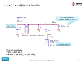
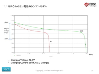
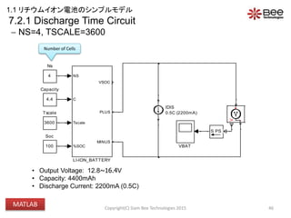
• The battery information refer to a battery part number PBT-BAT-0001 of BAYSUN Co., Ltd.
Copyright(C) Siam Bee Technologies 2015 20
The number of cells in
series is input as a
model parameter
Output Voltage DC 12.8~16.4V
Capacity of Approximately 4400mAh
Input Voltage DC 20.5V
Charging Time About 5 hours
Basic Specification
Li-ion needs 4 cells
to reach this
voltage level
1.1 リチウムイオン電池のシンプルモデル
SPICE
1. Benefit ofthe Model
2. Model Feature
3. Simulink Model of Lithium-Ion Battery
4. Concept of the Model
5. Pin Configurations
6. Li-Ion Battery Specification (Example)
6.1 Charge Time Characteristic
6.1.1 Charge Time Characteristic (Simulation Circuit)
6.1.2 Charge Time Characteristic (Simulation Settings)
6.2 Discharge Time Characteristic (Simulation Circuit)
6.2.1 Discharge Time Waveform - 1400mAh (0.2C discharge)
6.2.2 Discharge Time Waveform - 1400mAh (0.5C discharge)
6.2.3 Discharge Time Waveform - 1400mAh (1.0C discharge)
6.2.4 Discharge Time Characteristic (Simulation Settings)
6.3 Vbat vs. SOC Characteristic
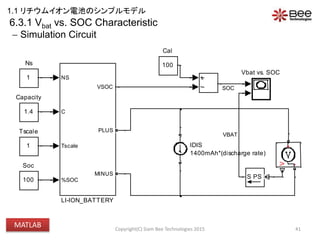
6.3.1 Vbat vs. SOC Characteristic (Simulation Circuit)
6.3.2 Vbat vs. SOC Characteristic (Simulation Settings)
7. Extend the number of Cell (Example)
7.1.1 Charge Time Circuit - NS=4, TSCALE=3600
7.1.2 Charge Time Waveform - NS=4, TSCALE=3600
7.2.1 Discharge Time Circuit - NS=4, TSCALE=3600
7.2.2 Discharge Time Waveform - NS=4, TSCALE=3600
7.3 Charge & Discharge Time (Simulation Settings)
8. Port Specifications
Simulation Index
Appendix Diode
25Copyright(C) Siam Bee Technologies 2015
1.1 リチウムイオン電池のシンプルモデル
MATLAB
26.
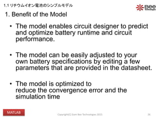
1. Benefit ofthe Model
• The model enables circuit designer to predict
and optimize battery runtime and circuit
performance.
• The model can be easily adjusted to your
own battery specifications by editing a few
parameters that are provided in the datasheet.
• The model is optimized to
reduce the convergence error and the
simulation time
26Copyright(C) Siam Bee Technologies 2015
1.1 リチウムイオン電池のシンプルモデル
MATLAB
27.
• This Li-IonBattery Simplified Simulink Model is for users who require the
model of a Li-Ion Battery as a part of their system.
• Battery Voltage(Vbat) vs. Battery Capacity Level (SOC) Characteristic, that can
perform battery charge and discharge time at various current rate conditions,
are accounted by the model.
• As a simplified model, the effects of cycle number and temperature are
neglected.
VSOC
2
MINUS
1
PLUS
VOC
+-
Rtransient_S
+-
Rtransient_L
+-
Rseries
Ibatt
+-
Ctransient_S
+-
Ctransient_L
+-
Capacity
2. Model Feature
27
Battery Circuit Model
Copyright(C) Siam Bee Technologies 2015
1.1 リチウムイオン電池のシンプルモデル
MATLAB
28.
3. Simulink Modelof Lithium-Ion Battery
28
Equivalent Circuit of Lithium-Ion Battery Model using Matlab
Copyright(C) Siam Bee Technologies 2015
1
VSOC
2
MINUS
1
PLUS
f(x)=0
Solver
Configuration
PSS
V
+
-
PS S
+-
0.03
RTS
0.034
RTL
IBAT
RTS
CTS
CAH
N
TSCALE
RTCT_S
RTCT_S_EQV
IBAT
RTL
CTL
CAH
N
TSCALE
RTCT_L
RTCT_L_EQV
IBAT
RS
N
CAH
RSO
RS_EQV
0.045
RS
PS S
PSS
+
-
U
+
-
U
-K-
-K-
f(u)
SOC VOUT
EOCV
I
+
-
1800
CTS
15000
CTL
TSCALE
CAH
IBAT
SOC_SETTING
SOC0
CAPACITY
+-
4
%SOC
3
Tscale
2
C
1
NS
1.1 リチウムイオン電池のシンプルモデル
MATLAB
29.
4. Concept ofthe Model
29
Li-Ion battery
Simplified Simulink Model
[Spec: C, NS]
Adjustable SOC : 0-100(%)
+
-
• The model is characterized by parameters: C, which represent the battery
capacity and SOC, which represent the battery initial capacity level.
• Open-circuit voltage (VOC) vs. SOC is included in the model as a behavioral
model.
• NS (Number of Cells in series) is used when the Li-ion cells are in series to
increase battery voltage level.
Output
Characteristics
Copyright(C) Siam Bee Technologies 2015
1.1 リチウムイオン電池のシンプルモデル
MATLAB
30.
VB
VIN
5V
1
Tscale
100
Soc
V
+
I
+
-
SENSE_IBAT
PSS
PS S
OUTPUT
1
Ns
NS
C
Tscale
%SOC
VSOC
PLUS
MINUS
LI-ION_BATTERY
ICHG
0.5C (700mA)1.4
Capacity
5.Pin Configurations
C is the amp-hour battery capacity [Ah]
– e.g. C = 0.2, 1.4, or 2.0 [Ah]
NS is the number of cells in series
– e.g. NS=1 for 1 cell battery, NS=2 for 2 cells
battery (battery voltage is double from 1 cell)
SOC is the initial state of charge in percent
– e.g. SOC=0 for a empty battery (0%), SOC=100
for a full charged battery (100%)
TSCALE turns TSCALE seconds into a second
– e.g. TSCALE=60 turns 60s or 1min into a second
TSCALE=3600 turns 3600s or 1h into a second
• From the Li-Ion Battery specification, the model is characterized by setting parameters
C, NS, SOC and TSCALE.
30
Model Parameters:
Probe
“SOC”
Copyright(C) Siam Bee Technologies 2015
1.1 リチウムイオン電池のシンプルモデル
MATLAB
7.3 Charge &Discharge Time
Simulation Settings
48
Table 5: Simulation settings
Property Value
StartTime 0
StopTime 8, 3
AbsTol auto
InitialStep auto
ZcThreshold auto
MaxConsecutiveZCs 1000
NumberNewtonIterations 1
MaxStep 0.01
MinStep auto
MaxConsecutiveMinStep 1
RelTol 1e-3
SolverMode Auto
Solver ode23t
SolverName ode23t
SolverType Variable-step
SolverJacobianMethodControl auto
ShapePreserveControl DisableAll
ZeroCrossControl UseLocalSettings
ZeroCrossAlgorithm Adaptive
SolverResetMethod Fast
Copyright(C) Siam Bee Technologies 2015
1.1 リチウムイオン電池のシンプルモデル
MATLAB
49.
8. Port Specifications
49
Table6
Parameter Simulink Simscape
NS O
C O
TSCALE O
%SOC O
VSOC O
PLUS O
MINUS O
VSOC
VIN
5V
60
Tscale
0
Soc
SENSE_
I
+
-
SENSE_IBAT
PS S
PS S
1
Ns
NS
C
Tscale
%SOC
VSOC
PLUS
MINUS
LI-ION_BATTERY
ICHG
0.5C
IBAT
1.4
Capacity
Battery Model
Copyright(C) Siam Bee Technologies 2015
1.1 リチウムイオン電池のシンプルモデル
MATLAB
50.
Appendix
50Copyright(C) Siam BeeTechnologies 2015
If Diode is error, Please choice Diode of SPICE-Compatiable
Semiconductors/Diode
1.1 リチウムイオン電池のシンプルモデル
MATLAB
51.
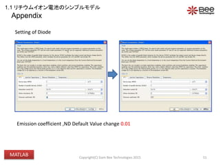
Appendix
51Copyright(C) Siam BeeTechnologies 2015
Setting of Diode
Emission coefficient ,ND Default Value change 0.01
1.1 リチウムイオン電池のシンプルモデル
MATLAB
52.
Copyright(C) Siam BeeTechnologies 2015 52
1.2 ニッケル水素電池のシンプルモデル
PSpice Version
LTspice Version
MATLAB Version
http://ow.ly/NQNU2
http://ow.ly/NQO3I
Copyright(C) Siam BeeTechnologies 2015 58
PSpice
IGBT
Model
PSpice
IGBT
Model
+
等価回路
MOSFET
+
BJT
SPICEの世界
3.IGBTのスパイスモデル
59.
Copyright(C) Siam BeeTechnologies 2015 59
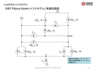
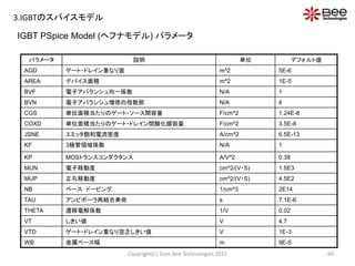
IGBT PSpice Model (ヘフナモデル) 等価回路図
dt/dQgs
dt/dQdg
dt/dQmult
dt/dQds
dt/dQcer
dt/dQeb
mosI
cssI bssI
multI
TI
E(S)
b(d)
G
C
e
5個のDC電流コンポーネントと
6個の容量性電荷コンポーネント
の構成です。
3.IGBTのスパイスモデル
60.
Copyright(C) Siam BeeTechnologies 2015 60
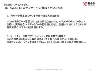
パラメータ 説明 単位 デフォルト値
AGD ゲート・ドレイン重なり面 m^2 5E-6
AREA デバイス面積 m^2 1E-5
BVF 電子アバランシュ均一係数 N/A 1
BVN 電子アバランシュ増倍の指数部 N/A 4
CGS 単位面積当たりのゲート・ソース間容量 F/cm^2 1.24E-8
COXD 単位面積当たりのゲート・ドレイン間酸化膜容量 F/cm^2 3.5E-8
JSNE エミッタ飽和電流密度 A/cm^2 6.5E-13
KF 3極管領域係数 N/A 1
KP MOSトランスコンダクタンス A/V^2 0.38
MUN 電子移動度 cm^2/(V・S) 1.5E3
MUP 正孔移動度 cm^2/(V・S) 4.5E2
NB ベース ドーピング 1/cm^3 2E14
TAU アンビポーラ再結合寿命 s 7.1E-6
THETA 遷移電解係数 1/V 0.02
VT しきい値 V 4.7
VTD ゲート・ドレイン重なり空乏しきい値 V 1E-3
WB 金属ベース幅 m 9E-5
IGBT PSpice Model (ヘフナモデル) パラメータ
3.IGBTのスパイスモデル
Motenergy, Inc (ME0913)
MotorElectrical Parameters
• Operating Voltage Range..........................0 – 72 VMAX
• Rated Continuous Current........................140 Arms
• Peak Stalled Current.................................400 Arms
• Voltage Constant.......................................50 RPM/V
• Phase Resistance (L-L).............................0.0125 Ω
• Phase Inductance......................................105uH at 120Hz, 110uH at 1kHz
• Maximum Continuous Power Rating……..17KW at 102VDC Battery Voltage
14.3KW at 84VDC Battery Voltage
12KW at 72VDC Battery Voltage
Motor Mechanical Parameters
• Rated Speed.............................................3000 RPM
• Maximum Speed.......................................5000 RPM
• Rated Torque............................................288 Lb-in
• Torque Constant.......................................1.6 Lb-in/A
Copyright(C) Siam Bee Technologies 2015 78
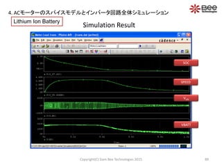
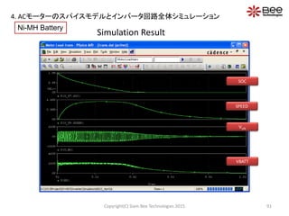
4. ACモーターのスパイスモデルとインバータ回路全体シミュレーション
79.
• The Torqueare defined by :
At 140Arms (Rated Continuous Current)
KT = 1.6 Lb-in/A
Tphe = 1.6 140 = 224Lb-in
Te = 224*3= 672Lb-in
• The Back-EMF are defined by :
At 5000 RPM (Maximum Speed)
Ephe ≈ VBAT (In an ideal motor, R and L are zero)
Ephe = 102V
KE = Ephe /ωm = 102 / 5000
KE ≈ 0.02V/RPM
Copyright(C) Siam Bee Technologies 2015 79
wTw
vTv
uTu
IKT
IKT
IKT
mEw
mEv
mEu
KE
KE
KE
phe: u, v, w
Vphe : Phase voltage applied from inverter to
motor
VAC : Operating voltage range (Maximum
voltage)
VBAT : DC Voltage applied from battery
Iphe : Phase current
Tphe : Electric torque produced by u, v, w phase
Te : Electric torque produced by motor
Ephe : Phase Back-EMF
KE : Back-EMF constant
KT : Torque constant
ωm : Angular speed of rotor
1 Pound Inch equals 0.11 Nm
TwTvTueT
(1)
(2)
(3)
4. ACモーターのスパイスモデルとインバータ回路全体シミュレーション
80.
Copyright(C) Siam BeeTechnologies 2015 80
L1
1 2
BEMF1
R1
L2
1 2
BEMF2
R2
L3
1 2
BEMF3
R3
N0
U
V
W
Phase Resistance (L-L) : 0.0125Ω
Phase Inductance : 105uH
: 110uH
Frequency Response
105uH
110uH
Fig.2 Phase-to-GroundFig. 1 Scheme of the 3-Phase Model
4. ACモーターのスパイスモデルとインバータ回路全体シミュレーション
81.
PARAMETERS:
KT = 1.6
KE= 0.02
LL = 105U
RLL = 0.0125
PARAMETERS:
LOAD = 140
U3
LM = {LL}
IL = {LOAD}
KT0 = {KT}
RM = {RLL*0.5}
1
2SPTQ
emf _u
0
IN+
IN-
OUT+
OUT-
EMF_V
eu
0
IN+
IN-
OUT+
OUT-
EMF_W
0
IN+
IN-
OUT+
OUT-
ELIM_V
0
lim_v
IN+
IN-
OUT+
OUT-
ESP
0
0
IN+
IN-
OUT+
OUT-
ELIM_W
lim_w
0
emf _vev
emf _u
-
+
+
-
E2
0
emf _v
emf _wew
-
+
+
-
E3
emf _w
0
n1
tu
0
tv
0
tw
N0
n2
U
n3
W
V
Vu
speedU4
AND3AMB
IN+
IN-
OUT+
OUT-
ETQ
0
mul
Vv
torque
Vw
-
+
+
-
E1
0
0
IN+
IN-
OUT+
OUT-
EMF_U
0
IN+
IN-
OUT+
OUT-
ELIM_U
0
lim_u
sp_v
sp_u
sp_u
sp_w
sp_w
sp_v
U1
LM = {LL}
IL = {LOAD}
KT0 = {KT}
RM = {RLL*0.5}
1
2SPTQ
U2
LM = {LL}
IL = {LOAD}
KT0 = {KT}
RM = {RLL*0.5}
1
2SPTQ
The 3-Phase AC Motor Equivalent Circuit
This figure shows the equivalent circuit of AC motor model that includes
the |Z|-frequency part ,Back-EMF voltage part ,and Mechanical part.
The Back-EMF voltage is the voltage generated across the motor's
terminals as the windings move through the motor's magnetic field.
Copyright(C) Siam Bee Technologies 2015 81
|Z| - Frequency Back-EMF Voltage
Mechanical part
Fig. 3 Three-Phase AC Motor Equivalent Circuit
4. ACモーターのスパイスモデルとインバータ回路全体シミュレーション
82.
Parameters Settings
Copyright(C) SiamBee Technologies 2015 82
LOAD : Load current each phase of motor [Arms]
– e.g. LL = 125Arms, 140Arms, or 400Arms
LL : Phase inductance [H]
– e.g. LL = 10mH, 100mH, or 1H
RLL : Phase resistance (Phase-to-phase) [Ω]
– e.g. RLL = 10mΩ, 100mΩ, or 1Ω
KE : Back-EMF constant [V/RPM]
– e.g. KE= 0.01, 0.05, or 0.1
KT : Torque constant [Lb-in/A]
– e.g. KT= 0.1, 0.5, or 1
1 Pound Inch equals 0.11 Nm
Model Parameters:
Fig. 4 Symbol of 3-Phase Induction Motor
From the 3-Phase Induction Motor specification, the model is characterized by
setting parameters LL, RLL, KE, KT and LOAD.
M N0
U1
ME0913
LL = 105U
LOAD = 140
KT = 1.6
KE = 0.02
RLL = 0.0125
1
2
3
4
4. ACモーターのスパイスモデルとインバータ回路全体シミュレーション
83.
Simulation Circuit of3-Phase AC Motor Model
Copyright(C) Siam Bee Technologies 2015 83
Fig.5 Analysis of motor operation powered by
alternating voltage variation involves using the model
of three-phase induction motor.
N0
N0
RU
RV
RW
U2
GDRV
UD
UP
VD
VP
WD
WP
RU, RV, RW: 173.75m
UP UD VDVP WP WD
V1
102V +
-
+
-
S1 D1
DMOD_01
+
-
+
-
S2 D2
DMOD_01
UP
UD
0
0
+
-
+
-
S3
M N0
U1
ME0913
LL = 105U
LOAD = 140
KT = 1.6
KE = 0.02
RLL = 0.0125
1
2
3
4
D3
DMOD_01
+
-
+
-
S4 D4
DMOD_01
VP
VD
0
0
+
-
+
-
S5 D5
DMOD_01
+
-
+
-
S6 D6
DMOD_01
WP
WD
0
0
U
0
V
W
V2
102V
4. ACモーターのスパイスモデルとインバータ回路全体シミュレーション
84.
Phase Current CharacteristicsUnder Load Variation
- Simulation Results
Copyright(C) Siam Bee Technologies 2015 84
Fig. 6 Current Characteristics under load Condition
Time
0s 500ms
I(RU)/SQRT(2)
-500A
0A
500A
Time
0s 500ms
I(RU)/SQRT(2)
-500A
0A
500A
Time
0s 500ms
I(RU)/SQRT(2)
-500A
0A
500A
Load 50Arms
Load 140Arms
Load 200Arms
Reference of Phase U
4. ACモーターのスパイスモデルとインバータ回路全体シミュレーション
About Control Signal(1/3)
Copyright(C) Siam Bee Technologies 2015 97
VD
WD
U
SPWM
CTL1
CTL2
CTL3
Vref 1
Vref 2
Vref 3
VP
WP
-
+
+
-
E7
E
-1
0
-
+
+
-
E8
E
-1
0
UP
UD
-
+
+
-
E9
E
-1
0
Double click
Output voltage (3-phase motor generator) feed to Vref1, Vref2 and Vref3
Control Signal of
Switching IGBT
To Connected to Motor
Generator
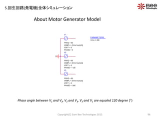
5.回生回路(発電機)全体シミュレーション
About Li-Ion Battery
Copyright(C)Siam Bee Technologies 2015 102
GND
GNDGND
D_disch
D9
V101
{(4.2*N)-8.2m}
IBATT
0Vdc
PARAMETERS:
N = 85
CAh = 50
rate = 1
PARAMETERS:
Voch = {(4.2*N)-8.2m}
Capacity = 1
HI
+ -
U9
LI-ION_BATTERY
SOC = 0
NS = {N}
TSCALE = {3600*4}
C = {CAh}
C2
10n
“N” is Amount
of Battery Cell
“TSCALE={3600*4}” is meant
1second (simulation setting-runtime)
equal 4 hours
“CAh” is Capacity of Battery
(ampere-hour capacity)
5.回生回路(発電機)全体シミュレーション
103.
Simulation Result (parametricsweep)
Copyright(C) Siam Bee Technologies 2015 103
Duty_buck=0.44 Duty_buck=0.34 Duty_buck=0.24
Battery Voltage
Battery Charging Current
Buck: Output Voltage
Buck: Gate Drive Voltage
3-phase rectifier: Output Voltage
3-phase Generator: Output Voltage
6 Hours
Simulation time for 1 condition is about 15 minute
5.回生回路(発電機)全体シミュレーション

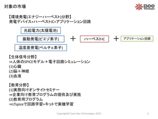


![Parameter Settings
C is the amp-hour battery capacity [Ah]
– e.g. C = 0.3, 1.4, or 2.8 [Ah]
NS is the number of cells in series
– e.g. NS=1 for 1 cell battery, NS=2 for 2 cells
battery (battery voltage is double from 1 cell)
SOC is the initial state of charge in percent
– e.g. SOC=0 for a empty battery (0%), SOC=1 for
a full charged battery (100%)
TSCALE turns TSCALE seconds into a second
– e.g. TSCALE=60 turns 60s or 1min into a second,
TSCALE=3600 turns 3600s or 1h into a second,
• From the Li-Ion Battery specification, the model is characterized by setting parameters
C, NS, SOC and TSCALE.
Copyright(C) Siam Bee Technologies 2015 14
Model Parameters:
+ -
U1
LI-ION_BATTERY
SOC = 1
NS = 1
TSCALE = 1
C = 1.4
(Default values)
1.1 リチウムイオン電池のシンプルモデル
SPICE](https://image.slidesharecdn.com/spicematlabevhev12jun2015-150629064259-lva1-app6891-150703001505-lva1-app6892/85/SPICE-MATLAB-EV-HEV-14-320.jpg)


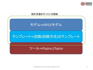
![4. Concept of the Model
29
Li-Ion battery
Simplified Simulink Model
[Spec: C, NS]
Adjustable SOC : 0-100(%)
+
-
• The model is characterized by parameters: C, which represent the battery
capacity and SOC, which represent the battery initial capacity level.
• Open-circuit voltage (VOC) vs. SOC is included in the model as a behavioral
model.
• NS (Number of Cells in series) is used when the Li-ion cells are in series to
increase battery voltage level.
Output
Characteristics
Copyright(C) Siam Bee Technologies 2015
1.1 リチウムイオン電池のシンプルモデル
MATLAB](https://image.slidesharecdn.com/spicematlabevhev12jun2015-150629064259-lva1-app6891-150703001505-lva1-app6892/85/SPICE-MATLAB-EV-HEV-29-320.jpg)
![VB
VIN
5V
1
Tscale
100
Soc
V
+
I
+
-
SENSE_IBAT
PSS
PS S
OUTPUT
1
Ns
NS
C
Tscale
%SOC
VSOC
PLUS
MINUS
LI-ION_BATTERY
ICHG
0.5C (700mA)1.4
Capacity
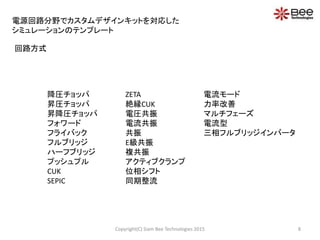
5. Pin Configurations
C is the amp-hour battery capacity [Ah]
– e.g. C = 0.2, 1.4, or 2.0 [Ah]
NS is the number of cells in series
– e.g. NS=1 for 1 cell battery, NS=2 for 2 cells
battery (battery voltage is double from 1 cell)
SOC is the initial state of charge in percent
– e.g. SOC=0 for a empty battery (0%), SOC=100
for a full charged battery (100%)
TSCALE turns TSCALE seconds into a second
– e.g. TSCALE=60 turns 60s or 1min into a second
TSCALE=3600 turns 3600s or 1h into a second
• From the Li-Ion Battery specification, the model is characterized by setting parameters
C, NS, SOC and TSCALE.
30
Model Parameters:
Probe
“SOC”
Copyright(C) Siam Bee Technologies 2015
1.1 リチウムイオン電池のシンプルモデル
MATLAB](https://image.slidesharecdn.com/spicematlabevhev12jun2015-150629064259-lva1-app6891-150703001505-lva1-app6892/85/SPICE-MATLAB-EV-HEV-30-320.jpg)


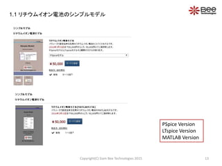
![Parameters Settings
Copyright(C) Siam Bee Technologies 2015 82
LOAD : Load current each phase of motor [Arms]
– e.g. LL = 125Arms, 140Arms, or 400Arms
LL : Phase inductance [H]
– e.g. LL = 10mH, 100mH, or 1H
RLL : Phase resistance (Phase-to-phase) [Ω]
– e.g. RLL = 10mΩ, 100mΩ, or 1Ω
KE : Back-EMF constant [V/RPM]
– e.g. KE= 0.01, 0.05, or 0.1
KT : Torque constant [Lb-in/A]
– e.g. KT= 0.1, 0.5, or 1
1 Pound Inch equals 0.11 Nm
Model Parameters:
Fig. 4 Symbol of 3-Phase Induction Motor
From the 3-Phase Induction Motor specification, the model is characterized by
setting parameters LL, RLL, KE, KT and LOAD.
M N0
U1
ME0913
LL = 105U
LOAD = 140
KT = 1.6
KE = 0.02
RLL = 0.0125
1
2
3
4
4. ACモーターのスパイスモデルとインバータ回路全体シミュレーション](https://image.slidesharecdn.com/spicematlabevhev12jun2015-150629064259-lva1-app6891-150703001505-lva1-app6892/85/SPICE-MATLAB-EV-HEV-82-320.jpg)


![Time
0.5s 1.0s
100*( (RMS(V(U,N0))*RMS(I(RU))) / (RMS(V(RU:1,N0))*RMS(I(RU))) )
0
50
100
(962.500m,81.941)
RMS(V(RU:1,N0))*RMS(I(RU))
0W
10KW
20KW
SEL>>
(960.616m,13.662K)
Power Output and Efficiency Characteristics At 140Arms
- Simulation Results
Copyright(C) Siam Bee Technologies 2015 87
Fig. 9 Power Output and Efficiency Characteristics at Load=140Arms
At Load=140Arms, Power Output ≈ 13.7 [KW]
At Load=140Arms, Efficiency ≈ 82 [%]
Watt
[%]
Reference of Phase U
4. ACモーターのスパイスモデルとインバータ回路全体シミュレーション](https://image.slidesharecdn.com/spicematlabevhev12jun2015-150629064259-lva1-app6891-150703001505-lva1-app6892/85/SPICE-MATLAB-EV-HEV-87-320.jpg)


![Block Diagram
Copyright(C) Siam Bee Technologies 2015 94
MG 3-phase rectifier Buck Li-Ion Battery
ChargeIGBT:300A/600V Step-down voltage
Maximum Voltage=4.2[V]
Capacity(CAh)=50[Ah]
Amount of Batteries(N)=85Cells
Vin=480[Vrms]
Vout=630[V]5
Vin=630[V] 5
Vout=200-360[V]
Frequency=50[Hz]
VMAX=400[V]
5.回生回路(発電機)全体シミュレーション](https://image.slidesharecdn.com/spicematlabevhev12jun2015-150629064259-lva1-app6891-150703001505-lva1-app6892/85/SPICE-MATLAB-EV-HEV-94-320.jpg)