This document contains information about spiral ductwork and fittings produced by Spiral Manufacturing Co., including:
- A table listing the weights of spiral galvanized pipe in various sizes and gauges.
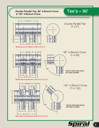
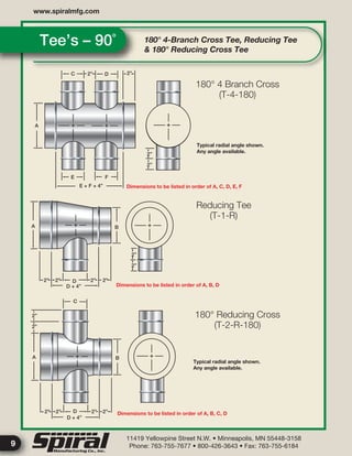
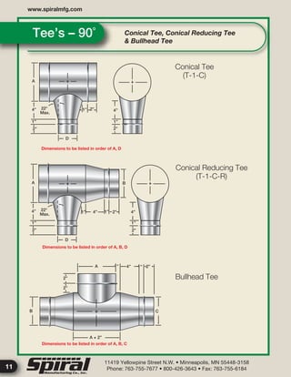
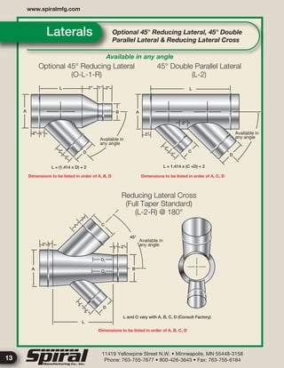
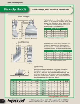
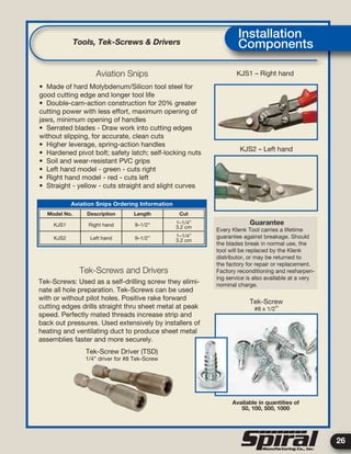
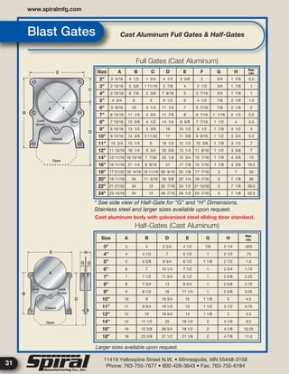
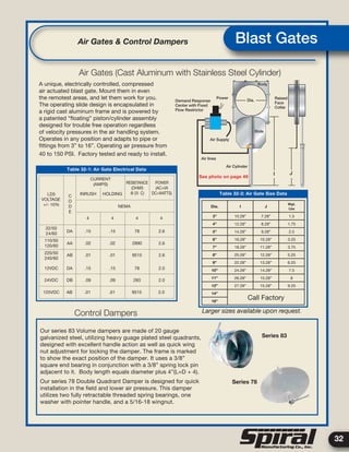
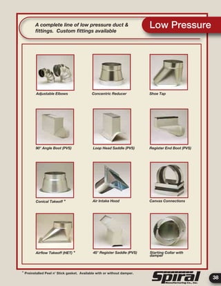
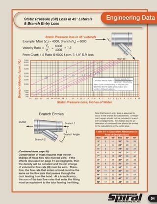
- Specifications for fittings like elbows, tees, laterals, manifolds, and other components.
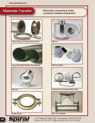
- Information on products like insulated duct, rectangular duct, dual wall duct and fittings, joints, and accessories.
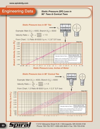
- Notes on applications, materials handling, product selection, and other general information.
The document provides specifications and details for a complete line of high pressure ductwork and pneumatic distribution systems.
This document discusses different types of air compressors. It describes reciprocating compressors which use pistons driven by crankshafts to compress air in cylinders. It also describes rotary compressors like centrifugal compressors which use rapidly spinning impellers to accelerate and compress air, and axial compressors which use alternating rows of fixed and moving blades to compress air. The document also discusses positive displacement compressors like roots blowers which use interleaving lobes to trap and compress air, and vane compressors which use sliding vanes and an eccentric rotor to vary chamber volumes and compress air.
This document presents a case study and methods to re-establish a condemned boiler. It includes an introduction, contents listing, acknowledgements, abstract on the Hindustan Storage & Distribution Company where the boiler is located, specifications and diagrams of the boiler, scope of dismantling and repair work, results of dismantling, scope of work after renovation including flue gas analysis and boiler tuning.
1. The document describes the basic components and working of a simple vapor absorption refrigeration system (VARS). It explains the working of the absorber, generator, condenser, expansion device and evaporator.
2. It then discusses the concept of circulation ratio and provides the steady flow analysis and governing equations for a VARS using the water-lithium bromide pair.
3. It also gives the key equations to calculate the COP, heat input/output of the various components, and provides a sample problem to calculate the COP and total heat rejection of a given VARS system.
The document discusses different types of compressors used to compress gases. It describes positive displacement compressors like reciprocating, screw, and rotary vane compressors which work by reducing the gas volume. Dynamic compressors like centrifugal compressors are also discussed which increase gas pressure using an impeller. Key components, working principles, advantages and disadvantages of reciprocating, screw, rotary vane and centrifugal compressors are summarized. Selection factors for compressors like required pressure, flow rates, piston speed and system layout are also highlighted.
The open gas-turbine cycle works as follows:
1. Air is compressed in a compressor, increasing its pressure and temperature.
2. The high-pressure air enters a combustion chamber where fuel is burned at constant pressure.
3. The high-temperature gas expands in a turbine, producing work and reducing to ambient pressure.
The Brayton cycle models the gas-turbine cycle with constant-pressure heat addition and rejection processes. Actual cycles have irreversibilities from non-isentropic compression/expansion and pressure drops. Efficiency can be improved with regeneration, intercooling, reheating, and multistage designs.
The document discusses cooling towers, including:
1. Types of cooling towers like natural draft, mechanical draft, forced draft, induced draft, cross flow and counter flow towers.
2. Parameters for assessing cooling tower performance including range, approach, effectiveness and cooling capacity.
3. Energy efficiency opportunities like selecting an appropriately sized tower, using efficient fill media to reduce pumping needs, and optimizing fans and motors.
The document discusses different types of sensors and transducers used to measure important process parameters such as flow, temperature, pressure, and level. It describes transducers as devices that convert one form of energy into another. It then provides details on various sensors used to measure temperature, including thermocouples, thermistors, RTDs, and pyrometers. It also discusses common pressure measurement techniques like manometric and elastic pressure transducers using devices like Bourdon tubes, bellows, and diaphragms.
Refrigeration and Air Conditioning
1.Refrigeration System
Two types of valves are used on machine air conditioning systems:
Internally-equalized valve - most common
Externally-equalized valve special control
Internally-Equalized Expansion Valve
The refrigerant enters the inlet and screen as a high-pressure liquid. The refrigerant flow is restricted by a metered orifice through which it must pass.
As the refrigerant passes through this orifice, it changes from a high-pressure liquid to a low-pressure liquid (or passes from the
high side to the low side of the system).
Let's review briefly what happens to the refrigerant as we change its pressure.
As a high-pressure liquid, the boiling point of the refrigerant has been raised in direct proportion to its pressure. This has concentrated its heat content into a small area, raising the temperature of the refrigerant higher than that of the air passing over the condenser. This heat will then transfer from the warmer refrigerant to the cooler air, which condenses the refrigerant to a liquid.
The heat transferred into the air is called latent heat of condensation. Four pounds (1.8 kg) of refrigerant flowing per minute through the orifice will result in 12,000 Btu (12.7 MJ) per hour transferred, which is designated a one-ton unit. Six pounds (2.7 kg) of flow per minute will result in 18,000 Btu (19.0 MJ) per hour, or a one and one-half ton unit.
Valve details
The refrigerant flow through the metered orifice is extremely important, anything restricting the flow will affect the entire system.
If the area cooled by the evaporator suddenly gets colder, the heat transfer requirements change. If the expansion valve continued to feed the same amount of refrigerant to the evaporator, the fins and coils would get colder until they eventually freeze over with ice and the air flow is stopped.
A thermal bulb has a small line filled with C02 is attached to the evaporator tailpipe. If the temperature on the tail pipe raises, the gas will expand and cause pressure against the diaphragm. This expansion will then move the seat away from the orifice,
This document describes closed feedwater heaters used in power plants. It discusses:
- Closed feedwater heaters are shell and tube heat exchangers that preheat boiler feedwater using extracted steam, improving cycle efficiency. No separate pumps are needed since streams remain at the same pressure.
- Advantages include reduced irreversibility in steam generation and avoiding thermal shock to boiler metal.
- Most power plants use a combination of open and closed feedwater heaters due to complexity and cost of closed heaters.
Pumps are mechanical devices that use prime mover energy to move fluids from one place to another. Positive displacement pumps apply pressure directly to the liquid using reciprocating or rotating components. The main types of positive displacement pumps are reciprocating pumps like piston pumps and diaphragm pumps, and rotary pumps like gear pumps. Reciprocating piston pumps use oscillating pistons to move fluid, and can be single or multi-cylinder designs. Axial and radial piston pumps use rotating cylinders to pump fluid. Diaphragm pumps use a reciprocating rubber diaphragm and check valves to pump fluid on each stroke. Positive displacement pumps are suitable for high-pressure applications and handling viscous or abrasive fluids.
This document provides an introduction to fundamental concepts in thermodynamics. It defines thermodynamics as the science concerned with energy storage and transformations, mostly involving heat and work. The three main concepts introduced are systems, surroundings, and boundaries. A system is the quantity of matter or region being studied, surroundings are outside the system, and boundaries separate the two. Thermodynamic properties can be intensive, like temperature, or extensive, like energy. Thermodynamic processes involve changes between equilibrium states.
Air compressors:- One of the important device used to compress air at high pressure.
The presentation contains a detailed information about air compressors, classification of air compressors, reciprocating air compressors, rotary type, multistage/ single stage compressors. advantages and lastly application/ uses of air compressors.
Hope You like the presentation.
1. There are multiple arrangements of combustion chambers used for different applications, including a single large chamber for heavy industrial power plants, multiple chambers for aircraft, and annular chambers best suited for compressors of axial flow type.
2. Combustion chambers must blend air and fuel efficiently, control the burning of large amounts of fuel and air, dampen hot combustion gases, and ensure expanded air with minimum pressure loss and maximum heat release.
3. Industrial combustion chambers are larger than aircraft chambers to allow longer residence times inside when fuel quality is poor and lower pressure drops due to lower flow velocities.
This document provides an overview of reciprocating compressors. It describes how reciprocating compressors work by using pistons moving back and forth in cylinders to compress air. The document discusses the types of reciprocating compressors, how they operate through intake and compression strokes, and diagrams to illustrate the compression process. It also covers startup procedures, safety concerns around carbon buildup and explosions, efficiency calculations, and specifications for a sample reciprocating compressor.
the water that reaches the surface is not hot enough to produce steam, it can still be used to produce electricity by feeding it into a Binary Power Plant. The hot water is fed into a heat exchanger. The heat from the water is absorbed by a liquid such as isopentane which boils at a lower temperature. The isopentane steam is used to drive turbines, producing electricity. The isopentane then condenses back to its liquid state and is used again.
The document discusses refrigeration systems used in aircraft. It describes several types of air refrigeration systems:
1) Simple systems use compressed air cooled by a turbine-driven fan for ground cooling.
2) Bootstrap systems add a secondary compressor driven by the turbine to increase cooling capacity for high-speed aircraft.
3) Regenerative systems further cool air in a secondary heat exchanger using bled refrigerated air.
4) Reduced ambient systems use two turbines, one for cabin air and one for cooling air, driven by a single fan to cool air below ambient temperatures for supersonic aircraft.
This document discusses duct design for air conditioning systems. It defines the functions of ducts as transmitting air from air handling units to conditioned spaces. It also covers duct classifications, economic factors influencing duct layout like heat gain/loss and friction, common duct design methods, and dynamic pressure losses in ducts. Finally, it discusses the requirements of air distribution systems and common types of air outlets.
This document discusses heat pipes and their applications in HVAC systems. It describes several projects using heat pipe heat exchangers (HPHEXs) for applications such as free reheat in dehumidification systems, waste energy recovery from building exhaust air, and heating emitters. It discusses the progress of a consortium working on novel heat pipe technology with funding from the SIRAC Kick-Start Fund, including designing a new heat exchanger, conducting market studies, and establishing long-term collaborative relationships between researchers and industry partners.
The document presents information on a bootstrap air cooling system suitable for aircraft. It consists of two heat exchangers, a secondary compressor driven by a turbine, and uses ram air and compression to cool and circulate air. Ambient air is compressed by the main aircraft compressor then cooled in an air cooler before further compression and cooling. It is then expanded through a turbine to provide cooled air to the aircraft cabin. Advantages are that air is readily available, non-toxic, and pressures are low. A limitation is that it requires aircraft flight for ram air cooling and is not suitable for ground use without an additional fan.
INTRODUCTION
THERMODYNAMIC CYCLE OF STEAM FLOW
RANKINE CYCLE (IDEAL , ACTUAL ,REHEAT)
LAYOUT OF STEAM POWER PLANT
MAJOR COMPONENTS AND THEIR FUNCTIONS
ALTERNATOR
EXCITATION SYSTEM
GOVERNING SYSTEM
Thermal power plants generate electricity through the combustion of fuel to produce steam that drives a steam turbine which spins an electrical generator. The document discusses several key components and considerations for thermal power plants, including their need for large quantities of fuel (typically coal), water, and land for ash storage. It also outlines the basic energy conversion process from fuel to electricity and highlights some common components like boilers, turbines, condensers, and coal and ash handling systems. Locating thermal plants requires consideration of factors like fuel availability, water sources, and ash disposal.
The document summarizes key concepts about thermodynamics cycles. It describes the processes that make up the Otto cycle used in spark-ignition engines, including isentropic compression, constant volume heat addition, isentropic expansion, and constant volume heat rejection. The thermal efficiency of the Otto cycle is defined. An example calculation illustrates determining temperatures, pressures, thermal efficiency, back work ratio, and mean effective pressure for an Otto cycle. The Diesel cycle used in compression ignition engines is also introduced.
This document discusses different types of steam turbines and their operating principles. It describes impulse turbines where steam expands within nozzles and does not change pressure as it passes over blades. Reaction turbines gradually decrease pressure as steam passes over fixed and moving blades. Compounding methods are also presented, including velocity compounding using multiple blade rings, pressure compounding with nozzle stages, and pressure-velocity compounding combining both methods. The document aims to explain steam turbine design and operation.
This document discusses different types of compressors used in mechanical engineering. It covers positive displacement compressors like roots blowers, vane compressors, and screw compressors. It also discusses steady flow compressors such as centrifugal and axial flow compressors. For each type of compressor, the document provides details on their working principles, applications, pressure ratios, flow rates and comparative advantages.
This document discusses various types of sensors and transducers. It begins by describing the fundamental elements of a measuring instrument, including the physical variable being measured, primary detector/transducer that converts the physical variable to an electrical signal, intermediate signal processing stage, and final output stage. It then compares electronic versus mechanical instruments. Key definitions of transducer, sensor and actuator are provided. The rest of the document discusses various types of sensors in more detail, including resistive, capacitive, inductive, strain gauges, temperature sensors, light sensors, and flow/speed sensors.
The document is a technical manual from Albion Sections that provides specifications for their zed purlins, c sections, and eaves beams. It includes dimensions, weights, connection details, and application examples for their cold formed galvanized steel profile sections. The manual aims to discuss advancements that provide more efficient strength to weight ratios and a better cost effective solution for customers. It also highlights their expanded product range, customization options, and increased production capacity.
The document describes fishing tools and services provided by Schlumberger for well construction and remediation. It provides details on 14 different tool types including casing backoff tools, external and internal casing patches, casing swages, releasing spears, mills, jars, bumper subs, junk baskets, scrapers and more. Each tool is briefly described including its applications, benefits, and key features. The document aims to provide oil and gas well operators with information on Schlumberger's fishing tool portfolio.
This document covers topics in fluid dynamics including the nature of fluids, fluid flow concepts, conservation equations, fluid flow in pipes and channels, compressible and multiphase flows, fluid distribution, mixing and flow through tube banks. Key aspects discussed include viscosity, laminar and turbulent flow, the continuity, momentum and energy equations, friction factors, velocity profiles, entrance and exit effects, orifice flow, the Mach number, nozzle flows, gas-liquid and gas-solid flows, distributors, stirred tanks, pipeline mixing and flow regimes in tube banks.
This document provides standards for gray iron pipe flanges and flanged fittings in classes 25, 125, and 250. It includes information on pressure-temperature ratings, sizes, marking, materials, fitting dimensions and tolerances, bolt and gasket dimensions, hydrostatic tests, and certifications. The document aims to establish uniform requirements for gray iron flanges and fittings to promote interchangeability.
Guide for the design of crane supporting steel structuresTimóteo Rocha
This document provides guidelines for the design of crane-supporting steel structures. It covers loads specific to these structures, design for repeated loads and fatigue, classification of structures, design and construction measures, and topics related to rehabilitation and upgrading of existing structures. The document contains several chapters that describe loads, fatigue design procedures, classification of crane service, examples of duty cycle analyses, design and construction checklists, and other topics such as clearances, attachments, and welding standards.
This document contains the rules and requirements for constructing power boilers according to the 2023 edition of the ASME Boiler and Pressure Vessel Code Section I. It outlines materials, design, openings, piping connections and other general requirements that must be followed. Markings like "ASME" can only be used if the item was constructed according to all applicable Code requirements and was formally ASME certified. The document also contains copyright information and a table of contents listing the specific rule sections covered.
This document is a parts manual for Doosan portable light towers. It contains diagrams and part listings for assemblies of the light towers. The manual provides information to assist with locating and ordering replacement parts for maintenance and repair of the light towers. It details the various subassemblies that make up the towers and the appropriate fasteners to use. Ordering parts requires specifying the model, serial number, part number and description.
This document provides information about tube service tools and equipment from Apex Tool Group, including specifications for tube rolling systems, condenser tube expanders, tube installation and removal tools, and boiler tube expanders. It lists contact information for Apex Tool Group sales and service centers around the world. The document contains a table of contents to help navigate the extensive product line information.
This is the Highly Detailed factory service repair manual for theCLAAS C490 CUTTER BAR, this Service Manual has detailed illustrations as well as step by step instructions,It is 100 percents complete and intact. they are specifically written for the do-it-yourself-er as well as the experienced mechanic.CLAAS C490 CUTTER BAR Service Repair Workshop Manual provides step-by-step instructions based on the complete dis-assembly of the machine. It is this level of detail, along with hundreds of photos and illustrations, that guide the reader through each service and repair procedure. Complete download comes in pdf format which can work under all PC based windows operating system and Mac also, All pages are printable. Using this repair manual is an inexpensive way to keep your vehicle working properly.
Service Repair Manual Covers:
Introduction
CCN Explanations
Safety Precautions
Gearbox / Clutch / Universal Drive Shaft
Drives
Hydraulic System
Crop Feeding
Feeder Unit
Mower Unit
Ground Guidance
Various Components / Machine Body
CCN (CLAAS Component Number)
Index
File Format: PDF
Compatible: All Versions of Windows & Mac
Language: English
Requirements: Adobe PDF Reader
NO waiting, Buy from responsible seller and get INSTANT DOWNLOAD, Without wasting your hard-owned money on uncertainty or surprise! All pages are is great to haveCLAAS C490 CUTTER BAR Service Repair Workshop Manual.
Thanks for visiting!
Claas c370 cutter bar service repair manualeudskkejedmm
This document is a repair manual that provides instructions for repairing various components of CLAAS C490-C370 machines. It includes sections on general repair instructions, specifications, safety precautions, and repair procedures for components like the universal drive shaft, intermediate drive shaft, and hydraulic lines. The manual describes how to remove, disassemble, inspect, replace, and install these parts correctly and safely. It also provides torque specifications for fasteners.
Claas c430 cutter bar service repair manualeudskkejedmm
This document is a repair manual that provides instructions for repairing various components of CLAAS C490-C370 machines. It includes sections on general repair instructions, specifications, safety precautions, and repair procedures for components like the universal drive shaft, intermediate drive shaft, and hydraulic lines. The manual describes how to remove, disassemble, inspect, replace, and install these parts. It also provides diagrams and torque specifications for fasteners.
Claas c490 cutter bar service repair manualjfdjskmdmme
This document is a repair manual that provides instructions for repairing various components of CLAAS C490-C370 machines. It includes sections on general repair instructions, specifications, safety precautions, and repair procedures for components like the universal drive shaft, intermediate drive shaft, and hydraulic lines. The manual describes how to remove, disassemble, inspect, replace, and install these parts correctly and safely. It also provides torque specifications for fasteners.
Claas c490 cutter bar service repair manualeudskkejedmm
This document is a repair manual that provides instructions for repairing various components of CLAAS C490-C370 machines. It includes sections on general repair instructions, specifications, torque settings, component numbers, safety precautions, and repair procedures for specific components like the universal drive shaft and intermediate drive shaft. The manual describes how to remove, disassemble, inspect, assemble and install these drivetrain components step-by-step. It also provides diagrams and an overview of the machine's drive system.
Claas c430 cutter bar service repair manualjfdjskmdmme
This document is a repair manual that provides instructions for repairing various components of CLAAS C490-C370 machines. It includes sections on general repair instructions, specifications, torque settings, component numbers, safety precautions, and repair procedures for specific components like the universal drive shaft and intermediate drive shaft. The manual describes how to remove, disassemble, inspect, assemble and install these drivetrain components step-by-step. It also provides diagrams and an overview of the machine's drive system.
Claas c370 cutter bar service repair manualjfdjskmdmme
This document is a repair manual that provides instructions for repairing various components of CLAAS C490-C370 machines. It includes sections on general repair instructions, specifications, torque settings, component numbers, safety precautions, and repair procedures for specific components like the universal drive shaft and intermediate drive shaft. The manual describes how to remove, disassemble, inspect, assemble and install these drivetrain components step-by-step and includes diagrams to aid the repair process.
This document is an installation, operation, and maintenance manual for the Griswold Model 811 ANSI Process Pump. It contains instructions for receiving, storing, installing, operating, maintaining, and repairing the pump. The manual includes sections on safety, installation procedures, operation guidelines, routine maintenance, spare parts ordering, and technical specifications. Diagrams and part lists are provided in the appendix sections. The document aims to ensure the safe and reliable operation of the pump when installation, operation, and maintenance instructions are carefully followed.
Great plains folding no-till drill parts manual PartCatalogs Net
This document is a parts manual for Great Plains 2N-2410 and 2N-3010 Folding No-Till Drills from 1995+. It contains over 100 pages detailing parts, assemblies, and components of the drills. The manual provides part numbers, diagrams, and instructions to assist with ordering replacement parts and maintaining the equipment. Safety warnings are included to notify the user of potential hazards. The document is copyrighted and its content may not reflect future product updates.
Catalog hitachi 50 hitachi-tr-series_dienhathe.orgDien Ha The
Khoa Học - Kỹ Thuật & Giải Trí: http://phongvan.org
Tài Liệu Khoa Học Kỹ Thuật: http://tailieukythuat.info
Thiết bị Điện Công Nghiệp - Điện Hạ Thế: http://dienhathe.vn
Kenworth W900 Heavy Duty Body Builder ManualTim Miller
This is the user manual of Kenworth W900.
>> READ MORE: https://www.obdadvisor.com/heavy-duty-truck-scan-tool/
This article shows a helpful in-depth review of the 9 best scan tools for heavy-duty trucks.
Preparing a suitable tool can helps you diagnose your car and make a wise decision before going to the repair shop. Visit our site to get the review and choose the best-matching scanner for your vehicle.
1. Volume 5
A COMPLETE LINE OF HIGH PRESSURE DUCTWORK
MANUFACTURERS OF COMMERCIAL AND INDUSTRIAL AIR CONDITIONING
AND PNEUMATIC CONVEYING DISTRIBUTION SYSTEMS
The Design StandardThe Design Standard
for Now and the Futurefor Now and the Future
Volume 5Volume 5
4. www.spiralmfg.com
1
11419 Yellowpine Street N.W. • Minneapolis, MN 55448-3158
Phone: 763-755-7677 • 800-426-3643 • Fax: 763-755-6184
Spiral Pipe Economy, Strength & Versatility
About Spiral Manufacturing Co., Inc.
Spiral Manufacturing Co., Inc. is a major
North American manufacturer of lock-seam,
high pressure Spiral
pipe and fittings.
We offer a complete
line of standard
commercial and
Industrial Spiral pipe,
fittings, and custom
fabrications designed
to meet all standard
specifications. Our
products are engineered and built to meet
or exceed all SMACNA (Sheet Metal and
Contractors National Association) standards,
and you can expect quality and on-time delivery,
whether you need a few components or a
complete system for a major installation. For
additional information, please visit our web site
at www.spiralmfg.com.
Advantages of Spiral Pipe
The advantages of high pressure Spiral pipe
compared to traditional rectangular duct are
numerous and compelling:
Attractive appearance—exposed Spiral duct
is attractive and is frequently specified by ar-
chitects because of
its superior aesthetic
appeal. Paintable
Spiral duct can be
finished to blend in
with, or stand out
from, the indoor envi-
ronment.
Economical to
install—the unique
attributes of Spiral duct can reduce installation
costs:
• Easier to install through and around
structural framing
• Longer spans reduces installation operations
and the number of connections and hangers
required
• Connections are made quickly and easily,
and are easier to seal.
Lower cost of ownership—Spiral duct reduces
upfront and operating costs:
• Low air leakage, optimal airflow
characteristics, and less pressure drop
allow smaller and more efficient air moving
equipment
• Inherently stronger, allowing the use of
lighter gauge, less costly metals
• Efficiently manufactured from strip steel to
any diameter
• Spiral duct’s smooth interior traps less dust
and is easier to clean
Many options and accessories—a solution
to almost any system design requirement:
• Manifold ducts efficiently handle complex
distribution requirements and reduce
installation time and cost
• Standard components for every
application, such as gored and die-
formed elbows, tees, laterals, pant
wyes, reducers,
rectangular to
round transitions,
pick-up hoods,
blast gates, clean-
outs, access
doors, diverters,
and many more
• Custom components can be engineered
for any purpose or specfic application
Available in many materials—meets a broad
range of applications:
• Galvanized G60-G901
• Paint Grip A-601
• Poly-vinyl coated1
• Aluminum 3003 H-142
• Stainless 304 or 3163
• Aluminized Steel
• Copper
1
ASTM A-653 • 2
ASTM B-316 • 3
ASTM A-240
Copper Spiral pipe
Spiral Manufacturing Co., Inc. head-
quarters—Minneapolis., Mn
Painted Spiral Duct used in a
retail application
Many standard fitings are in
stock at all times
5. 2
Standard Lateral Section
Corrugated Lateral Section
(Interior Side)
(Interior Side)
411
/16”
411
/16”
Broad range of applications—versatility:
• Commercial
• Industrial
• Chemical
• Underground
• Bulk materials
handling
Applications of Spiral
Pipe
The versatility of Spiral
duct has lead to its
use in a wide range of
applications:
Commercial—the primary use of Spiral duct
in commercial applications is for HVAC. Spiral
duct can now be found in numerous commercial
applications including:
• Restaurants
• Churches
• Sports facilities
• Community centers
• Clinics and hospitals
• Schools and universities
• Retail stores and malls
• Community and
entertainment facilities
• Office buildings and
warehouses
• And many more
Industrial—Spiral pipe’s ability to handle high
positive and negative pressures has led to
numerous industrial applications:
• HVAC
• Removal of chemical
fumes and other
environmental toxins
• Removal of dust
and other airborne
particulates
• Removal of
manufacturing by-
products such as
sawdust and wood
shavings
• Bulk material handling such as the loading of
grain trucks and hoppers.
Spiral Vinyl-Coated Pipe
The chemical inertness of PVC combined
with the strength of Spiral pipe make Vinyl
coated duct ideal for chemical fume removal
applications and for underground HVAC
applications where strength and resistance
to corrosive salts and other minerals found
in backfill are
prerequisites. Our
vinyl-coated Spiral
pipe is UL listed
and manufactured
from galvanized
steel coated with a
polyvinyl chloride
material with an
outside thickness
of 4 mils and inside
thickness of 1 mil standard. This is reversible
for special purposes. External corrugations are
standard for over 14” diameter for underground
applications. Standard gauges are: 4” to 16” /
24 gauge, 17” to 24” / 22 gauge, 26” to 48” / 20
gauge.
Spiral Insulated Pipe
Our dual-wall Spiral
insulated duct adds
both thermal insulating
and sound attenuating
benefits to any air
distribution system.
This dual-wall product
consists of inner and
Spiral Pipe is used extensively
in industrial applications
Dual wall Spiral pipe saves energy
and reduces noise. Shown without
insulation.
Spiral Duct in church blends
in with ceiling design
A Wide Range of Commercial &
Industrial Applications
Spiral Pipe
6. www.spiralmfg.com
3
11419 Yellowpine Street N.W. • Minneapolis, MN 55448-3158
Phone: 763-755-7677 • 800-426-3643 • Fax: 763-755-6184
Fittings & Accessories for Every ApplicationSpiral Pipe
Typical Pipe to Pipe Coupling Slip Joint
Typical Fitting to Pipe Slip Joint
For more Information see page 23
outer Spiral pipes with a layer of glass fiber
insulation sandwiched in between, thus reducing
noise and conserving energy.
Material Handling & Truck Loading
The ability of Spiral pipe to handle high
pressures, its efficient airflow characteristics,
and its low pressure
loss make Spiral
pipe ideal for bulk
material handling
applications. We
offer a complete
line of trailer loading
accessories,
including ball
joints, diverter valves, quick disconnects,
and air actuated gates. See pages 45-49 for
components and technical data.
Fittings
Spiral Manufacturing offers a complete line of seam
welded, slip-joint fittings designed especially for
use with Spiral pipe. Standard fittings include
many types of elbows, crosses, tees, laterals, re-
ducers, and other components fabricated from
standard 20 gauge steel (other gauges available).
Special Made Fittings
When you have requirements that cannot be
met by our standard fittings, we can fabricate
special fittings based on your specifications on
a time and materials basis. Once accepted for
production, orders for special fittings cannot be
canceled, nor can the finished fitting be returned
for credit. Please! Check your measurements
carefully!
In conclusion
Spiral pipe
combines the
economies
of light gauge
metal with a spiral
lockseam construction that assures maximum
strength and rigidity. Because of its superior
structural strength, the ductwork requires
fewer joints and hangers. Four plys of metal
form a continuous interlocked reinforcing rib
on the outside, which permits making long
lengths of pipe in various diameters, and
has a resistance to crushing approximately
2-1/2 times that of longitudinal lockseam
or welded pipe. Optional corrugations are
available which increase the rigidity of the
pipe by approximately 300%.
Developed for use on high
velocity, high-pressure air
conditioning systems,
Spiral pipe has
gained wide
acceptance
for all types of
high or medium
pressure, above and
below ground distribution
systems, such as ventilation, dust removal,
grain handling, carbon monoxide exhaust,
and dual wall pipe for sound and thermal
insulation. These are only a few of its
diversified applications.
Standard length in all diameters is 10 feet.
Any length between 6 and 20 feet cut at no
additional charge. Sizes range from 3” to 18” @
1” intervals and 20” to 80” @ 2” intervals.
For Physical Properites of Spiral Pipe and
Technical Information, see inside front cover and
Engineering Data pages 50 thru 60.
Typical Truck Loading application
7. 4
Item Page
Item numbers correspond with page
Spiral Pipe 1-3
Gored elbows 5
Die formed elbows 6
Tees 7-11
Laterals 12-13
Manifolds 14
Pant wye & Reducers 15
Plugs, Couplings, Offsets & Ball joints 16
Pick-up hoods 17
Weather hoods 18
Transitions 19
Rectangular Duct 20
Flanged connections 24-25
Hanger accessories 28-29
Clean out and Access doors 30
Blast Gates 31
Flexible Hose and accessories 33-34
Selection GuideSelect Product from Diagram and
Look Up Page Number from Table
8. 11419 Yellowpine Street N.W. • Minneapolis, MN 55448-3158
Phone: 763-755-7677 • 800-426-3643 • Fax: 763-755-6184
www.spiralmfg.com
5
Elbows Standard & Reducing Elbows are available in
any size and degree with optional radius
Typical Standards Shown
R=1½ x D
60°
2”
R=1½ x D
2”
D
90°
R=1½ x D
D
D
2”
45°
R=1½ x D
D
2”
30°
Dimensions shown are standard. Longer radius or more gore sections are available.
For other than standard, consult factory.
30° Gored Elbow
(E-2-30)
45° Gored Elbow
(E-3-45)
90° Gored Elbow
(E-5-90)
60° Gored Elbow
(E-4-60)
9. 6
ElbowsSpecial Application Elbows for sharp turns,
changing diameters & improved airflow
D
D 2”1”
90°
2”
A
R = D
2”
D
90°
R = 11
/2 x D
D
2”
R = 11
/2 x D
45°
Vanes provide smoother
airflow with sharp turnsVANE 1
VANE 2
3” to 7” = 1 vane
8” to 24” = 2 vane
For larger sizes consult factory
Available in any size and degree
with optional radius
Die-Formed Elbows allow for smoother airflow
See data on page 51
Die-formed elbows from 20 gauge are avaliable in both 90° and 45°. Ten standard
diameters from 3” to 12” are available. 14” are available on special order.
90° Mitered Elbow 2-Piece
(E-2-M-90)
Reducing Elbow
(RE-5-90)
Die-Formed Elbow
(E-1-90)
Die-Formed Elbow
(E-1-45)
10. 11419 Yellowpine Street N.W. • Minneapolis, MN 55448-3158
Phone: 763-755-7677 • 800-426-3643 • Fax: 763-755-6184
www.spiralmfg.com
7
Tee’s – 90˚ Plain Tee, 180° Cross Tee & 135° Cross Tee
A
D + 2”
D
2”
2”
C
D
2”1”
C 2”1”
A
D
135°
D + 2”
D + 2”
A
2”
2”
2”
Dimensions to be listed in order of A, D
Dimensions to be listed in order of A, C, D
Typical radial angle shown.
Any angle available.
Plain Tee
(T-1)
135° Cross Tee
(T-2-135)
180° Cross Tee
(T-2-180)
11. 8
Tee’s – 90˚Double Parallel Tee, 90° 4-Branch Cross
& 135° 4-Branch Cross
C + D + 4”
A
E
C D
2”
2”
2”
2”
2”
F
A
C D 2”
2” 2”
E + F + 4”
90°
C D
2”
A
E F
E + F + 4”
135°
2”
2”
2”
2”
2”
Typical radial angle shown.
Any angle available.
Typical radial angle shown.
Any angle available.
Dimensions to be listed in order of A, C, D
Dimensions to be listed in order of A, C, D, E, F
Double Parallel Tee
(T-2-P)
90° 4-Branch Cross
(T-4-90)
135° 4-Branch Cross
(T-4-135)
12. 11419 Yellowpine Street N.W. • Minneapolis, MN 55448-3158
Phone: 763-755-7677 • 800-426-3643 • Fax: 763-755-6184
www.spiralmfg.com
9
180° 4-Branch Cross Tee, Reducing Tee
& 180° Reducing Cross Tee
Tee’s – 90˚
C D
A
E F
2”
2”
2”
2”
2”
A B
D2” 2” 2” 2”
D + 4”
C
2”
2”
A
2” 2” 2” 2”D
D + 4”
E + F + 4”
2”
B
Typical radial angle shown.
Any angle available.
Typical radial angle shown.
Any angle available.
Dimensions to be listed in order of A, C, D, E, F
Dimensions to be listed in order of A, B, D
Dimensions to be listed in order of A, B, C, D
180° 4 Branch Cross
(T-4-180)
Reducing Tee
(T-1-R)
180° Reducing Cross
(T-2-R-180)
13. 10
Airflow Tee & Reducing Airflow Tee Tee’s – 90˚
L
A
D
2”
2”
1”
4”
D1
1”
L
A
2” 1”
B
2”1”1”
D
D1
4”
2”
1”
1”
Dimensions to be listed in order of A, D
Dimensions to be listed in order of A, B, D
Airflow Tee
(AFT-1)
Reducing Airflow Tee
(AFT-1-R)
Recommended for HVAC only.
Close coupling of elbows and branch
fittings should be avoided if at all
possible. The total pressure loss of two
close-coupled fittings will generally be
greater than the sum of the individual
fitting losses. For example: both the 45°
lateral and 45° elbow individually are
proved to be low loss fittings. However,
when they are joined to form a 90°
branch, the combined performance is
not as good as a conical tee or the
airflow tee. This is a particularly
important point to consider because
the airflow tee (this page) or conical
tee (next page) is less expensive and
is more compact than the combination
lateral-elbow. For best economy, the
designer should use the conical tee
or combination tee when low branch
losses are important; and the straight
90° tee should be used when a higher
loss fitting can be tolerated.
Engineering Note
14. 11419 Yellowpine Street N.W. • Minneapolis, MN 55448-3158
Phone: 763-755-7677 • 800-426-3643 • Fax: 763-755-6184
www.spiralmfg.com
11
Conical Tee, Conical Reducing Tee
& Bullhead Tee
Tee’s – 90˚
A
4”
2”
1”
D
2”1” 4”
1”
2”
A
4”
1”
2”
1” 4” 1” 2”
B
4”
1”
2”
D
A 1” 4” 1” 2”
C
A + 2”
B
2”
2”
22°
Max.
22°
Max.
Dimensions to be listed in order of A, D
Dimensions to be listed in order of A, B, D
Dimensions to be listed in order of A, B, C
Conical Tee
(T-1-C)
Conical Reducing Tee
(T-1-C-R)
Bullhead Tee
15. 12
45° Lateral, Tapered Reducing Lateral,
30° Lateral & Saddles
Laterals
Available in any angle. Standard is 45°
L = (1.414 x D) + 2 L and O vary with A, B, D (Consult Factory)
L = (2 x D) + 2
Boot
L
A
2” 1”
2”
2”
D
45°
A
2” 1” L 1” 2”
B
D
2”
L
A
2”
2”
1”
2”
D
30°
2”
2”
D
P
2”
O
2”
Dimensions to be listed in order of A, D Dimensions to be listed in order of A, B, D
Dimensions to be listed in order of A, D Dimensions to be listed in order of D, P.
Standard boot has 2” perimeter around branch.
Available with or without boot
Available in
any angle
Existing Pipe
30° thru 90°
Available in any angle. Standard is 45°.
45° Lateral
(L-1)
Tapered Reducing Lateral
(Standard)
(L-1-R)
30° Lateral
(L-1-30)
Saddles
16. 11419 Yellowpine Street N.W. • Minneapolis, MN 55448-3158
Phone: 763-755-7677 • 800-426-3643 • Fax: 763-755-6184
www.spiralmfg.com
13
Optional 45° Reducing Lateral, 45° Double
Parallel Lateral & Reducing Lateral Cross
Laterals
Available in any angle
L
A
2” 1”
2”
2”
D
B A
L
2”
2”
2”
C
D
2”
2”
2”
2” 1”
1” 2”
BA
2”
2”
D
L
C
L = (1.414 x D) + 2 L = 1.414 x (C +D) + 2
45°
2” 2”1”
L and O vary with A, B, C, D (Consult Factory)
O1
O2
Dimensions to be listed in order of A, B, D Dimensions to be listed in order of A, C, D
Dimensions to be listed in order of A, B, C, D
Available in
any angle
Available in
any angle
Available in
any angle
Optional 45° Reducing Lateral
(O-L-1-R)
45° Double Parallel Lateral
(L-2)
Reducing Lateral Cross
(Full Taper Standard)
(L-2-R) @ 180°
17. 14
Multi-Branch Laterals (Manifolds) Laterals
Available in any angle
1”
0°
90°
180°
270°
B
C
D
E
F
G
2”
2”
01
02
03
05
04
CC
DD
EE
FF
GG
2”
A
A
B
C
D
F
1”
2”
01
02
03
04
2”
1”
E
To order a multi-branch lateral (or manifold),
first give the dimensions of A, B, C, D, E, F,
G, etc. Then give the branch angle (45°
standard) and the radial angles if needed.
Example 1: 12 x 6 x 3 x 4 x 5 x 6 x 7 with
45° branch angles. All branches at radial
angle 0°
Example 2: 8 x 6 x 4 x 4 x 4 x 4 with 45°
branch angles. Branches C and E at radial
angle 0°. Branches D and F at radial angle
180°.
How to Order
Radial Angle
Example 1
Example 2
Branch angle
available in any
angle from
30° to 90°
18. 11419 Yellowpine Street N.W. • Minneapolis, MN 55448-3158
Phone: 763-755-7677 • 800-426-3643 • Fax: 763-755-6184
www.spiralmfg.com
15
Y-Branch or Pant Wye, Reducing Y-Branch,
Concentric Reducer & Eccentric Reducer
Pant Wyes / Reducers
B
2” 1”
A
B
2”
1”
A
2” 1”
B
1”
2”
C
45°
2” 2”1”
A B
Standard
4”
2”1”
1”
X
1”
2”
A
B
45°
Dimensions to be listed in order of A, B Dimensions to be listed in order of A, B, C
Any length available.
Dimensions to be listed in order of A, B
X varies with A and B. Consult factory.
Dimensions to be listed in order of A, B
Available in
any degree
Available in
any degree
Y-Branch or Pant Wye
(Y-2)
Reducing Y-Branch
(Y-2-R)
Concentric Reducer
(C-1-R)
Eccentric Reducer
(E-C-1-R)
19. 16
Specialty FittingsPlugs & Caps, Couplings, Offsets,
Ball Joints & Register Saddles
D
1”
Y
2”
X
3/4” Mounting Flange
B
A
L
F=3/4” P=Pipe
Size
3”
D
3/32”
D
53/8”
C
D
A
B
Max.
To order, specify “D” dimension
and P-1 or P-1-F. Also available
with bird screen.
To order, specify “D” dimension
and C-1 or C-1-F.
List dimensions in order of D, X, Y.
List dimensions in order of A, B, P.
L is available in any length.
41
/2”
Standard
D A B C
Wgt.
Lbs.
3” 5 3
/8 4 3
/4 23° 1
4” 7 1
/2 6 1
/2 23° 1.75
5” 9 7 7
/8 27° 2.5
6” 7 1
/2 8 7
/8 27° 3
7” 10 3
/8 7 7
/8 22° 4
8” 13 11 27° 7
9” 14 5
/8 12 27° 8
10” 14 5
/8 11 1
/4 22° 9
12” 16 1
/2 12 1
/4 20° 10
Spun steel galvanized ball joints provide flex-
ibility in ducts that serve moving equipment
such as cutter heads. The duct can swing
through an arc while maintaining exhaust flow.
Available in 3” through 12” diameter.
Table 17-1 Ball Joint Dimensions
Offset
Couplings
Pipe Coupling (C-1) fits into pipe
Fitting Coupling (C-1-F) fits over fitting
Plugs & Caps
Pipe Plug (P-1) fits into pipe
Fitting Cap (P-1-F) fits over fitting
Register Saddle
Ball Joint
20. 11419 Yellowpine Street N.W. • Minneapolis, MN 55448-3158
Phone: 763-755-7677 • 800-426-3643 • Fax: 763-755-6184
www.spiralmfg.com
17
Pick-Up Hoods Floor Sweeps, Dust Nozzles & Bellmouths
D W A B C
4” 10 6 81
/4 31
/2
5” 20 6 81
/4 31
/2
6” 20 6 81
/4 31
/2
Sizes Available
Other sizes are available on request
D A B E F R
4” 4 8 141
/2 51
/2 11
/2
5” 5 8 141
/2 6 11
/2
6” 6 10 161
/2 7 2
Sizes Available
Other sizes are available on request
D
6”
D
A
B
1”
5
/8”
2”
4”
W
F
D D
R
B
E
B
A
2”
4”
R
Open
Area
151
/4”
C
D
A
R
1˝
1˝
B
As the leader in the industry, Spiral Manufac-
turing Co., Inc. does not put doors on the open
area of Floor Sweeps for safety reasons. The
use of Blast Gates 42˝ above the floor saves
severed fingers and back injuries.
Radial Arm Saw hoods along with Chop Saw
Hoods are designed to be located behind
the sawblade in a fixed position. All standard
hoods are made of 18 gauge galvanized steel.
See page 19 for more hoods.
Bellmouth fittings are designed to the highest engineering
standards for maximum performance. They are used as a
take-off for a fast, solid, and highly efficient connection. This
conversion fitting, from a flat plenum or duct into Spiral pipe
greatly reduces turbulence and noise. The pressure drop char-
acteristics are superior to any other design.
Standard Radius Bellmouth
D A B R Wt. Lbs. D A B R Wt. Lbs.
3” 8 2.5 1.5 1.2 10” 16 3 2 2.4
4” 9 2.5 1.5 1.3 11” 19 4 3 3.6
5” 10 3 2 1.5 12” 20 4 3 3.8
6” 12 3 2 1.7 14” 22 4 3 4.4
7” 13 3 2 1.9 16” 26 5 4 6.5
8” 14 3 2 2.0 18” 28 5 4 7.1
9” 15 3 2 2.2 20” 30 5 4 7.3
Open Area
Floor Sweeps
Dust Nozzles
Bellmouths
21. 18
Weather HoodsSky Blasts, Storm Collars & Rain Caps
7”
2 x Dia.
Inner Baffle
(on DRC)
Stack
Dia.
1/2” Dia.
1/2” Dia.
Approx.
(SRC) Single Rain Cap (no inner baffle)
(DRC) Double Rain Cap (inner baffle)
Available with Bird Screen
D
D+6”
24”
6”
1
/2D+12”
D1
D1
+12”
12”
D1
= D+2”
D+4”
D sizes = All standard pipe sizes
shown on page 34
Semi-circular flaps (butterfly damper)
cover the exhaust stack when fan is
off. When fan is on, flaps are forced
out of the way to provide a clear path
for air movement. The built-in gutter
system is designed to prevent rain
and snow from entering the stack.
Made from galvanized Spiral pipe for
strength and durability; available in
most sizes. Pre-assembled for im-
mediate installation. Available with or
without Vanstone flange. See pages
24 and 25.
Shown flat. Pitched is also availableRoof Flashing (FL)
Sky Blast (SB)
Storm Collar (SC)
Rain Cap
22. 11419 Yellowpine Street N.W. • Minneapolis, MN 55448-3158
Phone: 763-755-7677 • 800-426-3643 • Fax: 763-755-6184
www.spiralmfg.com
19
Rectangular to Round Standard & Offset
Rectangular to Round
Transitions
X 1” 2”
B A1
A2
A3
A4
X 1” 2”
B
A1
A3
B1
B2
T1
When ordering with flange, list dimensions in order of A1
, A2
, A3
, A4
, B, X.
When ordering without flange, list dimensions in order of A1
, A3
, B, X.
When ordering with flange and offset round, list dimensions in order of A1
, A2
, A3
, A4
, B, X, B1
, B2
.
When ordering without flange, list dimensions in order of A1
, A3
, B, X, B1
, B2
, T1
.
For Offset Square to Round a print is required.
Shown with offset round, rectangular
end, and raw (plain end) T1
Shown with formed flange out
Raw (plain end) Formed Flange Out Angle Iron Flange
Rectangular to Round (Offset)
Rectangular to Round (Standard)
23. 20
Rectangular DuctRectangular Duct in Many Configurations
Elbow
radius throat and heel Box
Elbow
Square Throat Radius Heel End Cap
Goose Neck
Square Throat
Goose Neck
Radius Throat
Increased Area
Angular Takeoff
any angle
Elbow
square throat and heel
Elbow
radius throat and heel
Elbow
square throat, radius heel
Pan
Parker
Side Takeoff Tee
radius throat and heel
Standard
Transitioning Offset
Straight Backed
Offset
Straight Duct
Tee
radius throat and heel
Tee
square throat, radius heel Transition Pant Wye
T1
B
A
T1
T2R
T2
A
B
L
List dimensions in order of A, B, R, L, T1
, T2
Rectangular duct is available in almost
any size or shape.
Ends are available in:
• Raw (plain end) — T1
& T2
remain straight
• Formed Flange — T1
& T2
are turned out
• Angle Iron Flange — 1”, 11
/4”, 11
/2” & 2”
• Ductmate 35 and more
Standard and reducing
elbows are available in any
size and degree with optional
radius.
Angle iron plain or
punched (optional)
No job is too large or too small
for Spiral Manufacturing; and no
matter what size your job, you can
expect the highest quality and the
best service.
(SQD)
(SQF )
24. 11419 Yellowpine Street N.W. • Minneapolis, MN 55448-3158
Phone: 763-755-7677 • 800-426-3643 • Fax: 763-755-6184
www.spiralmfg.com
21
Dual Wall Pipe Dual Wall Insulated Spiral Pipe & Fittings
DENSITY
lbs. per
cu. ft.
Thick-
ness
Noise Reduction Coefficients at Frequencies
125 250 500 1000 2000 4000 NRC*
1.5
1” .17 .52 .57 .69 .82 .86 .65
11
/2” .23 .62 .74 .82 .87 .88 .75
2” .32 .70 .83 .91 .92 .91 .85
2.0
1
/2” .08 .42 .35 .46 .61 .75 .45
1” .19 .54 .61 .74 .86 .90 .70
11
/2” .25 .64 .78 .87 .94 .92 .80
2” .33 .76 .88 .94 .95 .94 .90
3.0
1
/2” .10 .40 .37 .53 .68 .79 .50
1” .21 .57 .70 .89 .95 .97 .80
11
/2” .27 .66 .85 .94 .97 .98 .85
2” .36 .79 .96 .99 .98 99 .95
DENSITY
lbs. per
cu. ft.
K R
1.5 .29 3.4
2.0 .27 3.7
3.0 .24 4.2
120° 120°
View A-A
D1
8”
Approx.
A
D2
A
Three l-beam spacers mini-
mum at approx. 120° center-
line spot welded to inner duct.
Duct liner absorbs equipment and air rush noises over a broad
spectrum of sound. Glass fiber construction traps noise and dis-
sipates it within the fiber matrix. Air is delivered, not noise. It also
performs as a thermal insulation to conserve energy.
Available in Perforated (Acoustical) Liner or
Solid (Thermal Insulation) Liners
3
/32”@ 3
/16” centers (stag-
gered). 33 holes per sq.
inch. Open area 23%.
Perforated
Section
(Actual Size)
Performance Chacteristics
(Sound Absorption)
*Overall Noise Reduction Coefficient (NRC)
Thermal
Conductance
All values are measured at 75°
mean temperature.
K factor is expressed as
Btu/in./ft2
/°F.
R is the reciprocal of K.
Insulation
Impregnated to
inhibit air born
fibers
Optional perforated liner
See detail drawing below.
l-beam spacers
Application Note
Zinc on galvanized pipe melts at 788° F.
The Manual of Industrial Ventilation Recommended Prac-
tice, 23rd Edition, suggests that operating temperatures
not exceed 400° F.
Standard duct liner maximum temperature rating 250° F.
R-value of duct liner per inch of thickness = 3.6.
Aluminized Type 1 - 1250° F.
25. 22
Dual Wall FittingsDual Wall 60° & 90° Elbows, Dual Wall Plain
Tee & Dual Wall Reducing Tee.
D1 D2
2”
1”
60°
R=11
/2 xD1
R=11
/2 xD1
90°
2”
2”
1”
D1
D2
A1
A2 A1
A2
D2
+ 2” D2
+ 2”
2”
2”
2”
2”
2”
2”
2”1” 1” 1”1”
1”4”
B1
B2
D1
D2
D1
D2
When ordering, list dimensions in order of:
A1
, A2
, D1
, D2
When ordering, list dimensions in order of:
A1
, A2
, B1
, B2
, D1
, D2
When ordering, list dimensions in order of:
D1
, D2
When ordering, list dimensions in order of:
D1
, D2
All fittings in this catalog are available in dual wall construction. See examples above.
All 90° elbows are of 5 piece construction, and all 45° elbows are of 3 piece construction.
Elbow centerline radius is not less than 11
/2 times the inside duct diameter.
Dual Wall 60° Elbow
(DW-E-4-60)
Dual Wall 90° Elbow
(DW-E-5-90)
Dual Wall Plain Tee
(DW-T-1)
Dual Wall Reducing Tee
(DW-T-1-R)
26. www.spiralmfg.com
11419 Yellowpine Street N.W. • Minneapolis, MN 55448-3158
Phone: 763-755-7677 • 800-426-3643 • Fax: 763-755-618423
Slip Joints & Flange-to-Flange Joints
Coupling: Use standard C-1-F coupling or,
in the field, cut a short length of spiral pipe.
Fitting to Fitting slip joint
Pipe to Pipe slip joint
Flange to Flange Joint
Spiral pipe is designed to be easy to install:
all pipe ends are female, and all fitting ends
are male, allowing pipe and fittings to easily
slip together. There are several methods of
joining Spiral pipe and fittings, depending
on your application and your applications
requirements.
Slip Joints
Slip joints are the simplest method of joining
Spiral pipe:
Fitting-to-fitting joints (male to male) require
a separate coupling, C-1-F; or a short, hand-
cut section of Spiral pipe can be used as a
coupling for quick, in-the-field connections.
Pipe-to-pipe joints (female to female) also
require a separate C-1 coupling.
Pipe-to fitting joints slip together without the
need of a separate coupling.
Slip joints are fastened with screws or
pop-rivets, and duct sealant or sealant tape
(page 27) when additional air tightness is
required. (The screws or rivets hold the pipe
in place as the sealant cures.) The standard
recommendation is for screws or pop-rivets
to be used at a maximum of 15” intervals with
no fewer than three screws or pop-rivets per
joint. Spiral Manufacturing recommends a
maximum interval of 6”.
Flange-to-Flange Joints
Flange-to-flange joints are widely used
to connect pipes in dust and fume control
applications, in outdoor applications, and for
additional strength in high positive or high
negative pressure applications. Flange-
to-flange joints are fastened with bolts for
permanent installations and for installations
where the pipe must mate with fans or other
air moving equipment. Flange clamps are
used when there is a need for frequent, or
occasional, maintenance or cleaning. Flange
ends are fabricated by using angle rings (p.
25) to create a Vanstone Flange connection
(p. 24).
No Coupling: Pipe sections (female) and
fittings (male) are sized to slip together.
Pipe to Fitting slip joint
Coupling: Use standard C-1 coupling. The
C-1 coupling is also used with flexhose.
Installation
27. 24
Step 1
Slip flange over Spiral ductwork allowing
duct to extend 1/2” beyond the face of the
flange. Measure to ensure the flange is square to
the duct. Secure flange in place with 3 or 4 C-
clamps.
Step 2
Peen 4 tabs about 1” wide and 90° apart, work-
ing from the inside of the flange. The edge of the
flange acts as a break. Do not cut, slice, or ham-
mer directly on the end of the duct.
Step 3
Rotate duct 45° and peen 4 more tabs about 1”
wide and 90° apart. There should now be a total
of 8 tabs bent over.
Step 4
Peen remaining edge of duct over flange. Flange
is ready to be bolted.
Field Installation of
Vanstone Flanges
Spiralmate
Spiralmate® flanges are airtight and easy
to install, and no additional sealants are
required. They can be installed on-site, they
are easy to align, and they use a one-bolt
closure. Spiralmate fits Spiral seam and most
ribbed pipe, and it accommodates moderate
variations in pipe diameter.
Spiralmate is available in diameters from 8” to
72” in 2” increments. For one-inch increments
and sizes larger than 72”, consult the factory.
The Spiralmate system is comprised of four
components: two flanges with integral mastic
injected into the duct receiving pocket, a
gasket, and a closure ring and bolt. See photo
on page 25.
Spiralmate® Joints
Step 2
Step 4
Face View
Face of
Angle
Ring
Spiral Manufacturing offers professionally
mounted Vanstone flanges on Spiral pipe and
fittings. For most installations, this is the easiest
and most secure option. There may be times,
however, when Vanstone flanges must be
mounted at the installation site. We have included
mounting instructions below to assist you.
Closure ring
Flange
Duct wall
Gasket
Duct wall Mastic
Duct
recieving
pocket
INNER RING FLANGES
One ring is attached to
each duct end.
CLOSURE RING applies
pressure to Inner Flange Rings
to form a permanent airtight
connection.
Spiralmate-S
(10” - 34” duct)
Spiralmate-L
(36” - 72” duct)
SEALANT permanent non-
hadrdening mastic injected
in during manufacture.
GASKET Ductmate Neo-
prene gasket is applied to
flange face before joining
duct.
FASTENER forms
a permanent at-
tachment between
flange and duct.
1 - 1/4”
13/16”
1-1/2”
1-1/4”
5/8”
Duct wall
See Page 25 for sizes.
InstallationVanstone Joints & Spiralmate® Joints
29. 26
Model No. Description Length Cut
KJS1 Right hand 9–1/2” 1–1/4”
3.2 cm
KJS2 Left hand 9–1/2” 1–1/4”
3.2 cm
• Made of hard Molybdenum/Silicon tool steel for
good cutting edge and longer tool life
• Double-cam-action construction for 20% greater
cutting power with less effort, maximum opening of
jaws, minimum opening of handles
• Serrated blades - Draw work into cutting edges
without slipping, for accurate, clean cuts
• Higher leverage, spring-action handles
• Hardened pivot bolt; safety latch; self-locking nuts
• Soil and wear-resistant PVC grips
• Left hand model - green - cuts right
• Right hand model - red - cuts left
• Straight - yellow - cuts straight and slight curves
Tek-Screws: Used as a self-drilling screw they elimi-
nate all hole preparation. Tek-Screws can be used
with or without pilot holes. Positive rake forward
cutting edges drills straight thru sheet metal at peak
speed. Perfectly mated threads increase strip and
back out pressures. Used extensively by installers of
heating and ventilating duct to produce sheet metal
assemblies faster and more securely.
KJS1 – Right hand
KJS2 – Left hand
Guarantee
Every Klenk Tool carries a lifetime
guarantee against breakage. Should
the blades break in normal use, the
tool will be replaced by the Klenk
distributor, or may be returned to
the factory for repair or replacement.
Factory reconditioning and resharpen-
ing service is also available at a very
nominal charge.
Tek-Screw
#8 x 1/2”
Tek-Screw Driver (TSD)
1/4” driver for #8 Tek-Screw
Available in quantities of
50, 100, 500, 1000
Tools, Tek-Screws & Drivers
Installation
Components
Aviation Snips Ordering Information
Aviation Snips
Tek-Screws and Drivers
30. www.spiralmfg.com
11419 Yellowpine Street N.W. • Minneapolis, MN 55448-3158
Phone: 763-755-7677 • 800-426-3643 • Fax: 763-755-618427
Duct Sealant & Aluminum Foil TapeSealants & Tapes
601 & 321 Tubes601 & 321 Gallons 1520CW Alum. Foil Tape 1402AFQ Sealant Tape
Application Data for 601 and 321 Duct Sealants
Color........................................................................................................................................................... Gray
Application/Storage Temperature ..............................................................................................35° F to 110° F
Service Temperature................................................................................................................- 20° F t0 200° F
Pressure Classes ....................................................................... SMACNA 1
/2, 1, 2, 3, 4, 6 and 10 inches w.g.
Seal Classes.......................................................................................................................... SMACNA A, B , C
Method......................................................................................................Brush, putty knife, caulk gun, pump
Rate............................................. Apply at joint and fastener to 20 mil thick wet film after duct work installed
Clean up (wet) ...........................................................................................................................Soap and water
Packaging ............................................................................................................. 10 ounce tube; 1 gallon can
Coverage (1 gallon) ..................................................................................................... 500 feet x 2 inches wide
Coverage (1 tube)........................................................................... 65 feet at 1/4” bead; 130 feet at 1/8” bead
Product/
Description Color-Size Adhesive
Thickness/
Tensile-
Strength
Peel Adhesion/
ServiceTemp.
U.L. Listed/
Flame Spread/
Smoke Devop.
Pressure
Class/
Seal Class
Precautions
1520CW
Dead-soft alumium
foil; Silicone release
liner.
Aluminum-2” x
50yds
Cold Weather
Acrylic
3.5 mil
27 lbs/inch width
96 oz. per in. width
-35 F to 260 F
723 Class A
5
10
None None
1402AFG
Mill finish alum.
substrate with gray
adhesive sealant
Aluminum or Paint-
able-2” x 100ft.
100% solid elas-
trometric modified
butyl
2 mil Aluminum, 15
mil Gray Matter
955 psi avg.
16 lbs. per lin. Inch
35 F to 110 F
723 Class A
20
40
SMACNA 1,2,3,4
and 6 inches w.g.
SMACNA A,B,C
Yes
See MSDS
Premium Indoor/Outdoor Flexible
Water Based Duct Sealant
601 Duct Sealant
Specifications Compliance: Passes ASTM C-731,
ASTM D-2202. USDA, EPA and FDA Approved.
321 Duct Sealant
Fiber reinforced Indoor/Outdoor
Water Based Duct Sealant
Aluminum Foil Tape
A versatile, all purpose, fiber-free, duct sealant
for use on all types of metal duct, glass fiber duct
board, flex duct, duct fabric and flexible tubing
runouts. Distinguished by its ability to accommodate
minor vibration and movement, S2 - 601 stays
flexible to save call-back labor. S2 - 601’s excellent
coverage and easy brush-on application provide low
installation cost while providing proven reliability.
S2 - 321 is an all purpose industrial grade duct
sealant for all types of metal duct, glass fiber duct
board, and flex duct, as well as duct fabric and
flexible tubing runouts. It includes UV inhibitors
for extended outdoor exposure and built-in fiber
reinforcement for added strength. This non-toxic
water based product is solvent free and is suitable
for residential use.
Specifications Compliance: Passes ASTM D-2202,
ASTM C-731. USDA, EPA and FDA Approved
31. 28
Weights and Sizes of Single and Double Rod Hangers
Size
Wgt.
(Lbs.)
Size
Wgt.
(Lbs.)
Size
Wgt.
(Lbs.)
Size
Wgt.
(Lbs.)
3” .5 12” 1.3 24” 3.8 42” 6.4
4” .6 13” 1.4 26” 4.1 44” 6.7
5” .7 14” 1.4 28” 4.3 46” 6.9
6” .7 15” 1.5 30” 4.7 48” 7.2
7” .8 16” 1.6 32” 4.9 50” 7.5
8” .9 17” 1.7 34” 5.2 52” 7.8
9” 1.0 18” 1.8 36” 5.5 54” 8.1
10” 1.1 20” 1.9 38” 5.8 56” 8.4
11” 1.2 22” 3.5 40” 6.1 60” 9.1
Sizes thru 20” are 1-1/2” x 16 gauge
Sizes 22” and above are 2” x 14 guage
Maximum
Diameter of
Round Ducts
Straps Description
10” 0.047” (No. 18 guage) galvanized steel 2” wide
20” 0.058” (No. 16 guage) galvanized steel 2” wide*
40” 1/8” steel x 1-1/2”*
60” 1/8” steel x 2”*
Over 60” 3/16” steel x 2”*
Vertical Ducts
Maximum
Diameter of
Round Ducts
Straps Description
10”
Same gauge as galvanized steel duct, 1’’ wide or
(No. 8 gauge galvanized steel wire) on 10’ centers
20” Same gauge as galvanized steel duct, 1’’ wide
or (No.8 gauge galvanized steel wire) tied to 1’’
galvanized steel band around duct on 10’ centers40”
60”
Same gauge as galvanized steel duct, 1-1/2’’ wide
on 6’ centers
Over 60”
Same gauge as galvanized steel duct,
1-1/2’’ wide on 4’ centers
Horizontal Ducts
* Spaced vertically not more than 12 ft. on centers
Reproduced from International Uniform Mechanical Code. As local
codes differ, it is the responsibility of the user to determine that
hangers listed will satisfy local regulations. Spiral Manufacturing Co.,
Inc. assumes no responsibility other than the sizes and material
listed in the Spiral Standard Hangers table above.
Hex Nut
(Plated)
Coupling
(Plated)
Flat Washer
(Plated)
Single Rod
Double Rod
Hardware supplied upon request.
• 10’ by 1’’ Hanger Strap, 16 guage,
25 per bundle.
• 100’ by 3/4’’ Hanger Band Rolls,
24 guage, slotted.
3/8”-16 and
1/2” - 13
3/8” and 1/2”
Threaded Rod
3/8”-16 and 1/2”-13
Length: 36” and 72”
Wall Mount
9/16” holes
standard on
3/8”-16 and
1/2” - 13
by 1-3/4” long
Hanger
Accessories
Single and Double Rod Hangers, Nuts,
Washers & Threaded Rods
32. www.spiralmfg.com
11419 Yellowpine Street N.W. • Minneapolis, MN 55448-3158
Phone: 763-755-7677 • 800-426-3643 • Fax: 763-755-618429
Hanger
Accessories Beam clamps, struts & Speed Link®
RS
Rod
Size
D F T
Max. recom.
load (lbs.)
Top Bottom
3/8”
BC
1-1/8” 3/8” 3/8” 500 250
1/2”
BC
1-1/16” 1/2” 1/2” 950 760
Malleable iron casting with a hardened cup
point set screw and locknut. UL listed. Set
screw must be tightened onto the sloped side
of the I-Beam, channel or angle iron flange and
torque to 60 inch pounds. May be mounted in
either position.
The Universal Support System is a stand-
alone hanging system that supports a wide
variety of applications.
This system comprises
a galvanized steel air-
craft cable with integral,
self-locking hook and a
patented locking device
that allows quick instal-
lation and release for
adjustment or removal.
The system is available in 2mm and 3 mm
cable sizes, which support 100lb. and 200 lb.
loads respectively. Both have a 5-to-1 safety
factor.
Thread lock-
ing device onto
cable
Fasten cable
to beam with
beam clamp
Or wrap cable
around beam
RS
D
T
F
3
/4
”
I-Beam Top I-Beam Bottom
1-5/8” x 1-5/8” 12 Ga.
Half-Slot (HS)
1-1/8” x 9/16” slots
punched on 2” centers
Wrap cable
around duct
Thread cable
back through
locking device
Release cable
with unlocking
tool or small
screwdriver
Installation
Sammy Screws (BCW)
Sammy screws are-
designed to quickly
fasten threaded rod
to wood beams and
trusses. They are
available in 3/8” and
1/2” sizes.
Beam Clamp
(Model 300 (BC)
Strut
Universal Support System
The Universal Support System is cULus®
listed and has a DIN 4102-2 F30-A fire rating
of 30 minutes for 2mm wire rope and an F60-
A rating of 60 minutes for 3mm wire rope.
33. 30
Size A B C D E R
Wgt.
Lbs
6” 9 51
/2 23
/4 63
/4 4 3 11
/2
8” 9 55
/8 21
/4 63
/4 4 4 13
/4
10” 9 53
/4 23
/8 63
/4 4 5 2
12” 111
/8 63
/8 23
/8 91
/8 41
/2 6 21
/2
14” 111
/4 61
/2 23
/8 91
/8 41
/2 7 3
16” 111
/4 61
/2 21
/4 91
/8 41
/2 8 3
Size A B C D E
Wgt.
Lbs
41
/2
”x9” 113
/8 63
/4 15
/8 91
/4 43
/4 21
/2
9” x 18” 20 111
/8 15
/8 18 9 5
18” x 18” 21 21 15
/8 18 18 16
Size A B C D E R
Wgt.
Lbs
4” 6 31/2 17/8 33/4 23/8 2 1/2
6” 87/8 53/8 21/2 6 37/8 3 1
8” 87/8 55/8 21/6 61/4 4 4 11/2
10” 87/8 55/8 2 61/4 4 5 11/2
12” 83/4 61/2 13/4 61/4 4 6 11/2
14” 111/8 61/2 2 81/2 41/2 7 21/4
16” 11 61/2 13/4 81/2 41/2 8 21/4
18” 11 61/2 13/4 81/2 41/2 9 21/4
20” 11 61/2 13/4 81/2 41/2 10 21/2
22” 11 61/2 13/4 81/2 41/2 11 21/2
24” 11 61/2 13/4 81/2 41/2 12 21/2
Gasket
(Hinged Only)Typ.
A
D
E
R
B
C
A D
E
B C
Opening
Opening
Opening
Opening
Cover
5/32” Dia. Mtg.
hole typical
Mounting
lip
B
AHinge
P = pipe size
Mounting
flange
Over Center
clasp
3/4” x 1/8”
gasket
Aluminum, Contoured and Hinged,
Clean-Outs & Access Doors
Aluminum Contoured Hinged
Aluminum Flat Hinged
Aluminum Contoured – (removable cover)
Galvanized Access Door (Contoured or Flat)
Clean-Outs
35. 32
Dia. I J
Wgt.
Lbs
3” 10.28” 7.28” 1.5
4” 12.28” 8.28” 1.75
5” 14.28” 9.28” 2.5
6” 16.28” 10.28” 3.25
7” 18.28” 11.28” 3.75
8” 20.28” 12.28” 5.25
9” 22.28” 13.28” 6.25
10” 24.28” 14.28” 7.5
11” 26.28” 15.28” 8
12” 27.28” 15.28” 9.25
14”
Call Factory16”
Table 32-1: Air Gate Electrical Data
Table 32-2: Air Gate Size Data
A unique, electrically controlled, compressed
air actuated blast gate. Mount them in even
the remotest areas, and let them work for you.
The operating slide design is encapsulated in
a rigid cast aluminum frame and is powered by
a patented “floating” piston/cylinder assembly
designed for trouble free operation regardless
of velocity pressures in the air handling system.
Operates in any position and adapts to pipe or
fittings from 3” to 16”. Operating air pressure from
40 to 150 PSI. Factory tested and ready to install.
Our series 83 Volume dampers are made of 20 gauge
galvanized steel, utilizing heavy guage plated steel quadrants,
designed with excellent handle action as well as quick wing
nut adjustment for locking the damper. The frame is marked
to show the exact position of the damper. It uses a 3/8”
square end bearing in conjunction with a 3/8” spring lock pin
adjacent to it. Body length equals diameter plus 4”(L=D + 4).
Our series 78 Double Quadrant Damper is designed for quick
installation in the field and lower air pressure. This damper
utilizes two fully retractable threaded spring bearings, one
washer with pointer handle, and a 5/16-18 wingnut.
See photo on page 49
Larger sizes available upon request.
Air Supply
Demand Response
Center with Fixed
Flow Restrictor
Air lines
Body
Raised
Face
Collar
Slide
Air Cylinder
Series 83
Series 78
JI
Air Gates & Control Dampers Blast Gates
Dia.
Power
Air Gates (Cast Aluminum with Stainless Steel Cylinder)
Control Dampers
36. www.spiralmfg.com
11419 Yellowpine Street N.W. • Minneapolis, MN 55448-3158
Phone: 763-755-7677 • 800-426-3643 • Fax: 763-755-618433
Warning: To reduce the risk of static discharge igniting sus-
pended particulates, the flex hose helix wire must be grounded
to both the duct system and the machine as shown above.
Inside
Dimension
(inches)
Approx.
Wgt.
(lbs./ft.)
Minimum
Centerline
Bend
Radius
(inches)
Com-
pression
Ratio
Maximum
Recom-
mended
Negative
Pressure
(in./Hg)
Maximum
Recom-
mended
Positive
Pressure
(psi)
2 .19 1.4 5:1 29 30
2.5 .29 1.4 5:1 19 30
3 .3 1.8 5.5:1 29 30
4 .46 2.7 6:1 24 22
5 .56 3.4 5.5:1 13 18
6 .66 3.8 6.5:1 8 15
7 .73 4.2 6.5:1 8 10
8 .65 5.2 6.5:1 2 7
10 1.1 6 6.5:1 2 7
12 1.3 7 6.5:1 1.7 6
14 1.5 8.4 6.5:1 1.1 5
16 1.7 9.6 6.5:1 .7 4.6
18 1.9 11 6.5:1 .5 4.1
Note: Technical data based on 2 ft. straight lengths of hose @ 72° F.
Table 33-1: Flexible Hose Properties
• Construction: Light duty clear polyurethane wall hose
construction reinforced with a spring steel wire helix.
• Product Features:
• Excellent compressibility
• Cut, gouge, and chemical resistant
• Efficient flow characteristics
• Designed for wide temperature ranges
• Maximum flexibility and abrasion resistance
• Applications: Recommended for industrial air
movement, fume control, and dust collection applications.
• Temperature Range: -65° F to 225° F
• Diameter Range (Inches I.D.): 2”-18”
(Available to 24”)
• Standard Lengths: 10, 15, and 25 Feet
• I.D. Tolerances (Inches): Up to 8”: -0.00 to +0.125; 8”
and over: -0.00 to +0.250 Inch
• End Finish: Plain Cut
• Standard Color: Standard LD color: clear
Standard HD color: black
Flexible clear polyurethane hose is tough and du-
rable, and suitabe for a wide variety of appiications.
See clamps on next page.
Typical machine application
Flx-Thane LD (4” and 12” shown)
Flexible Hose Cross-Section
Flexible Hose Clear Clear Polyurethane Hose & Fittings
Flexible Clear Polyurethane Hose (LD)
Hose
Coupling
HD Flex Hose
Disconnect
J-Lock
Coupling
Strip polyurethane cover from helix wire
and fasten with sheet metal screw through
clamp and into duct and machine collar.
37. 34
No. Range
02HC 113
/16 - 23
/4
˝
03HC 29
/16 - 31
/2
˝
04HC 31
/2 -51
/2
˝
05HC 41
/2 - 61
/2
˝
06HC 53
/4 - 73
/4
˝
07HC 61
/2 - 81
/2
˝
08HC 2 - 10˝
10HC 91
/2 - 111
/2
˝
12HC 11 - 13˝
14HC 121
/2 - 141
/2
˝
16HC 153
/8 - 173
/8
˝
18HC 18 - 20˝
Housing 301
Stainless Steel
Screws
5
/16
˝ Hex Hd.
Stainless
Steel
Band
201/301
Stainless
Steel
Band Thickness
.021/026 inches
Band Width
.05 Inches
Diam.
Range
1.2˝
Max.
Table 34-1:
Hose Clamp Sizes
Bridge clamps provide a tight seal
on right-hand (standard) spiral wire
flex hose. Band and housing are
Type 301 stainless steel. Band is
1
/2
˝ wide and 0.025˝ thick. Screw is
Type 305 stainless.
Note: To determine the spiral
direction of your hose, look
at the end of the hose. If the
spiral goes away from you in a
clockwise direction, then the
hose has a right-hand spiral.
Inside
Diameter
(inches)
Minimum
Inside Throat
Radius
(inches)
Approx.
Weight Per
Foot
(lbs.)
2” 6.34 .70
3” 9.75 1.02
4” 12.00 1.38
5” 16.25 1.70
6” 19.50 2.00
7” 22.75 2.33
Table 34-2:
U100 .010”- .012” strip thickess
Inside
Diameter
(inches)
Minimum
Inside Throat
Radius
(inches)
Approx.
Weight Per
Foot
(lbs.)
8” 30.00 4.65
9” 36.00 5.22
10” 40.00 5.78
12” 48.00 6.91
Table 34-3:
U120 .018”- .020” strip thickess
Flexible Steel Hose & Hose Clamps Flexible Hose
Flexible steel hose is strip-wound interlocked and
made from hot-dipped galvanized carbon steel. There
are two different gauge thicknesses to choose from,
depending on the severity of service. It can be twisted
without unraveling. Steel flex is rated to 788°
F. Spiral
Manufacturing suggests that operating temperature
not exceed 400°
F. It is sold fully extended and may be
less than specified length if compressed.
From fully collapsed, tubing can be extended 2.5’’ per foot under a tension load of 25-lbs. minimum to 45-lbs.
maximum. Install in systems in semicompressed condition, midway between fully extended and fully compressed.
Galvanized steel all metal suction and blower hose for
dust and fume collection. An excellent choice for wood
shop molders.
Flexible Steel Hose
Hose Clamps
Bridge Clamps
For clear polyurethane and black heavy duty (HD) flexible hose only
38. www.spiralmfg.com
11419 Yellowpine Street N.W. • Minneapolis, MN 55448-3158
Phone: 763-755-7677 • 800-426-3643 • Fax: 763-755-618435
Underground Duct
PVS (Polyvinyl Steel) coated underground HVAC
duct (also known as PCD, PVC coated, and
PVCS) is UL® listed and specified more often by
architects, engineers, and contractors than any other
underground air delivery system because it offers
both the strength of steel and the inertness of plastic.
These attributes make PVS ideal for in underground
as well as corrosive fume exhaust
applications, such as in the plating
industry.
How PVS is manufactured
PVS is manufactured by a three step
process: 1) hot-dipped, galvanized G-
60 steel is cleaned and fire treated; 2) a
special epoxy primer is baked onto both
sides of the sheet; 3) Finally, a 4 mil.
polyvinyl chloride coating is heat fused onto one side
(4 x 1) for underground HVAC or onto both sides (4 x
4) for chemical fume exhaust applications. The result
is a tough, corrosion resistant surface that will not
crack, chip, peel, or rust.
Advantages of underground PVS duct
• Placing ductwork underground results in a more
aesthetically pleasing interior. Acoustical aesthetics
is also improved since most or all of the “rumble”
associated with interior duct is significantly reduced
or eliminated.
• The space between the ceiling and roof can be
reduced, making it easier to install electrical and fire
suppression systems.
• Installing duct underground allows the air delivery
system to be designed for optimum efficiency
because ducts do not have to run through, or parallel
to roof supports. In addition, runs inside interior or
exterior walls can often be eliminated.
• Underground duct is a cost effective solution when
air needs to be supplied to adjacent or contiguous
buildings because a central unit can serve all
locations.
• PVS duct requires no protection from concrete or
the minerals and salts found in backfill.
• It is strong enough to walk on and will carry
moderate soil loads; yet it can be cut or modified
on the jobsite with circular or saber saws fitted with
metal cutting blades.
Installation
Although PVS duct has been used successfully
in underground applications for over 30 years,
successful results depend on correct installation
procedures.
Engineering Considerations:
• It is always recommended that duct systems–
whether above or below grade–be
designed by a qualified engineer and
installed by a qualified contractor.
When a concrete slab will not cover
underground duct, special consideration
must be given to potential future loading
from heavy equipment. If such loading
is expected, PVS duct can be incased
in concrete, in which case the duct
will need to be securely tied down
to prevent “floating.” When a concrete slab will
cover the duct, loading is not as critical, but it is
recommended that the duct not be buried deeper
than 2.5 times its diameter. At depths greater than
2.5 times the diameter, additional measures must
be taken to insure the duct does not collapse.
Such measures include the use of painted angle-
iron flange connectors for added stiffness at joints,
special reinforcing around the duct, or (on ducts 36”
or larger) internal reinforcement. Consult a qualified
engineer when such measures are required or when
there is any concern about loading.
Preparing the sub grade:
• PVS duct can be placed directly on the soil with no
special precautions to protect the duct. However,
drainage needs to be considered because standing
water may eventually find its way into the duct
causing mold and odor problems. The grade should
always be sloped back to the utility room, and never
place PVS duct at or below the water table.
• It is recommeded that the duct be placed on 2”
to 6” of pea gravel or other material that will permit
easy drainage, especially when soil conditions are
marginal. (Although not required to protect the duct,
a vapor barrier should be placed under the duct
and below the entire slab to prevent moisture from
percolating through the concrete.)
Underground Duct Advantages, Description & Installation of
Underground Duct Systems
39. 36
Spiral Manufacturing Co., Inc. offers a broad line
of Class 1 PVS Spiral pipe and fittings. We build
custom made fittings and hoods on request to
accompany our standard product line. Our PVS
products comply with the following codes and
industry standards:
The duct, encased either in concrete or buried
directly below a concrete slab, is installed above the
original line of undisturbed soil and above the water
table. Encasing the duct in concrete with porous fill
beneath is the best way to install PVS duct. An optional
vapor barrier can be placed between the pipe and the
fill. Always consult local building codes for specific
installation instructions.
Table 36-1: Load Specifications
Diameter
(inches)
Max. Loading
(lbs./linear ft.)
8” or less* 400
9” to 13–1/2”* 600
14” to 36”** 1800
*Uncorrugated **Corrugated
All ducts 14” or larger are corrugated for underground applica-
tions. Loading specifications for ducts larger than 36” have not
been determined.
Precautions and limits:
Sheet metal duct is flexible, not rigid, so greater
care must be taken when installing PVS duct.
Three parameters need to be considered:
External load (soil load = point load), soil stiffness
(modulus), and pipe stiffness. In the absence of
test data, a soil modulus of 200 PSI and a soil
density of 120 lbs/ft3
can be used in calculations.
Consult with an engineer. PVS Temperature
Limits: Operating temperatures for PVS range from
-40° F to 250° F, with limited exposure to 400° F.
UL 181 Class 1
International Mechanical Code 1996 Section 603
ICBO Uniform Mechanical Code - (UMC) 1997
SMACNA Sheet Metal Air Conditioning
Contractors National Association
Connecting and fastening:
PVS Duct and fittings (or connectors) have male and
female ends, respectively, and they are designed to slip
together. Before joining, PVC sealant must be applied
to the outside of the female fitting (or connector) and
the inside of the duct. The joint must then be fastened
around its circumference with sheet metal screws
spaced no more than 6” apart and with a minimum of
three screws per joint. Sealant should then be applied
to the joint’s edge and to screw heads. After the sealant
has cured, the joint should be wrapped with two to three
layers of PVC tape.
Spot surface repair:
The plastic surface of PVS duct is exceptionally tough,
but it can be scratched. When scratches expose bare
metal, they should be sealed with PVC tape or PVC
Touch-Up Paint spray. Having these remedies available at
the jobsite helps to assure that this detail is not neglected.
Backfilling:
After the duct has been placed, spread backfill evenly in
several layers (depending on the diameter of the pipe) and
tamp each layer. Tamping should be done carefully to
avoid denting or scratching the pipe’s surface; do not use
mechanical tampers since their shockwaves can severly
damage the duct. Do not toss backfill directly on the duct
since this may cause denting, scratching, or even collapse
if a large weight of fill is dumped directly onto the pipe.
Similar care should be taken if concrete is being used to
encase the duct.
SLAB REGISTER
OPTIONAL
VAPOR BATTIER
POROUS FILL
SOIL
BACK
FILL FOUNDATION
GRADE LINE
PVS
DUCT
WATER TABLE
Corrugated Lateral Section
(diameters 14” and above)
Standard Lateral Section
(diameters 4” to 131
/2”)
(Interior Side)
411
/16”411
/16”
(Interior Side)
Connecting, Fastening & Backfilling Underground Duct
40. www.spiralmfg.com
11419 Yellowpine Street N.W. • Minneapolis, MN 55448-3158
Phone: 763-755-7677 • 800-426-3643 • Fax: 763-755-618437
The terms “low” pressure and “high” pressure in
duct design and selection have, unfortunately,
been given a rather wide latitude of meanings
in the HVAC industry over the years. The terms
have been applied to “pressure” and “velocity”
simultaneously because they are inter-
dependant in ductwork design. This section
of the catalog is devoted to the definition and
selection of “low” pressure equipment and
components.
The dividing line for “velocity” of air in ducts
has been defined in various applications as
anywhere from 1500 to 2500 fpm and nominally
as 2000 fpm. Empirical data has shown that
duct sections operate satisfactorily over the
above range of velocities at 1˝ water gage (˝wg).
Low pressure systems are chosen where duct
space allows, where air noise is a consideration,
and where particle conveyance such as wood
chips or grain is not a requirement.
Space limitations in modern buildings have
restricted the size of air conditioning ducts
and equipment. Therefore, to convey the
necessary volumes of air, higher velocities must
be employed. Increased velocities produce
higher duct friction losses. In order to maintain
flow against the higher duct friction, it is
necessary to have greater pressures at the air
source. Therefore, the terms “high pressure”
and “high velocity” generally go hand in hand.
Conversely, this is true of “low pressure” and
“low velocity”.
The use of the terms “high velocity” and “high
and medium pressure” in this catalog refer to
any static pressure class of 3˝ wg or greater,
and “low pressure” refers to 2˝ wg or less.
SMACNA recommendations on pressure and
velocity are shown in Table 37-1. The listed
classifications pertain to ducts only. Casing
and plenum construction designs are provided
in the SMACNA “Low Pressure” manual and in
the “High Pressure” manual, but their respective
designs have been based on historical
acceptability.
1
Reproduced in part by Permission From SMACNA High Pressure
Duct Standards - 3rd Ed.
2
Seal Class A: All seams, joints, fastener penetrations and
connections sealed.
3
General velocity level through this pressure rated section of
the system. Certain points may have higher or lower velocities,
e.g., fan outlet or restricted passage, yet not require a different
pressure class. The designer makes determinations of duct class
after analyzing velocities and operating pressures.
Low Pressure A complete line of low pressure duct &
fittings — in stock and available
Table 37-1: Pressure Velocity Classification 1
Former
Duct
Class
Pressure
Rating
Pressure
Seal
Class2
Velocity
(fpm)3
High
Pres.
10” Pos. A 2000 Up
Medium
Pres.
6” Pos. A 2000 Up
Medium
Pres.
4” Pos. A 2000 Up
Medium
Pres.
3”
Pos. or
Neg.
A 4000 Dn
Low
Pres.
2”
Pos. or
Neg.
2000 Dn
Low
Pres.
1”
Pos. or
Neg.
2000 Dn
Low
Pres.
½”
Pos. or
Neg.
1500 Dn
Spiral Manufacturing stocks a complete line of low
pressure fittings and installation accessories.
41. 38
Low PressureA complete line of low pressure duct &
fittings. Custom fittings available
* Preinstalled Peel n’ Stick gasket. Available with or without damper.
Adjustable Elbows Concentric Reducer Shoe Tap
Register End Boot (PVS)
Conical Takeoff *
90° Angle Boot (PVS) Loop Head Saddle (PVS)
Air Intake Hood Canvas Connections
Airflow Takeoff (HET) * 45° Register Saddle (PVS) Starting Collar with
damper
42. www.spiralmfg.com
11419 Yellowpine Street N.W. • Minneapolis, MN 55448-3158
Phone: 763-755-7677 • 800-426-3643 • Fax: 763-755-618439
Why you need a dust collection system
Installing an efficient dust collection system
should be a priority for the small shop as well
as the large shop, whether the material being
machined is wood, plastic, or a composite. Not
only is this essential for health reasons and
compliance with many national and local codes,
but it is also good business because it saves
money and helps to maintain the quality of the
finished product.
The harmful health effects of inhaled
particulates (many of which are carcinogens)
are well documented, and skin, eye, and
nose problems as well as allergic reactions
are frequently reported. In addition, a dusty
shop increases the risk of worker injury and
fire, which can result in lost production, higher
insurance rates, and lawsuits.
A dusty shop compromises the quality of the
finished product: Accurate measurements and
cuts are more difficult due to lack of visibility;
airborne dust finds its way into finishing areas
causing defects in the final product; and larger
particles cling to surfaces cause scoring and
other defects.
Finally, dust that is not automatically collected
must be collected manually as a recurring direct
labor expense.
By any measure, an efficient dust collection
system is an investment that more than pays for
itself.
Designing a dust collection system
In the simplest terms, a dust collection system
is comprised of a ducting system to transport
the dust from the source (table saw, planer,
etc.) and a collection device (such as a bag and
filter system or a cyclone), which pulls the dust
through the ducting and collects it. The very
first decision you must make is whether your
ducting will be metal or plastic—and here there
is only one logical choice: metal. (See “Metal
vs. Plastic Duct” below.) The next step is to size
your system. (See “Designing Your System” on
pages 41-44.)
Metal vs. Plastic Duct
Plastic pipe (or PVC pipe) is unsuitable for
dust collection for three reasons:
• First, plastic pipe fittings are not offered
in the diversity required to meet design
requirements.
• Second, plastic pipe elbows have a
short radius, which encourages clogs and
compromises system efficiency.
• Third, and most important, plastic pipe
is non-conductive and builds up a static
charge as charged particles pass through
it. This static charge can discharge at any
time causing shock and surprise, which
is dangerous around running machinery.
More serious is the risk of explosion and
fire. Fine dust particles suspended in air
have significant explosion potential—all
that is needed is a spark, which the static
charge on plastic pipe conveniently supplies.
Grounding plastic pipe requires wrapping it
in wire both inside and out—an expensive
(and never certain) proposition that negates
the minimal price savings in going to plastic
in the first place.
Spiral steel pipe has none of these
disadvantages. An incredible variety of
fittings are available and custom fittings
can be easily fabricated. The fittings are
designed with long radius to minimize
clogging, and special fittings such as clean-
outs and quick disconnects are available.
Most important, Spiral metal pipe is
conductive, and simple and easy to ground,
even when flexible rubber hose is used to
connect the duct to the machine.
Dust Collection The importance of dust collection & choos-
ing the right type of duct for dust collection
43. 40
Standard dust collection components
& accessories
Dust Collection
Spiral Manufacturing has all the duct components you need to design
and build a safe and efficient dust collection system
Laterals (Pages 12-14) Reducers (Page 15) Elbows (Pages 5-6)
Blast Gates (Pages 31-32) Clean-outs (Page 30) Floor Sweeps (Page 17)
Clear Flex Hose (Page 33) Manifolds (Page 14) Custom Hoods (Page19)
Clamps (Page 34) Bellmouth (Page 17) Duct Sealants (Page 27)
44. www.spiralmfg.com
11419 Yellowpine Street N.W. • Minneapolis, MN 55448-3158
Phone: 763-755-7677 • 800-426-3643 • Fax: 763-755-618441
How to design an efficient dust collection
system with Spiral pipe.
Table 41-1: Velocity for Type of Dust
Type of Dust
Velocity
in Branches
(FPM)
Velocity
in Main
(FPM)
Metalworking Dust 5000 4500
Woodworking Dust 4500 4000
Plastic/Other
Light Dust 4500 4000
Table 41-2: CFM for for pipe diameter at specified velocity
Diameter 3500 FPM 4000 FPM 4500 FPM
3” 277 316 356
4” 305 348 392
5” 477 546 614
6” 686 784 882
7” 935 1068 1202
8” 1222 1396 1570
9” 1546 1767 1988
10” 1909 2182 2455
12” 2749 3142 3534
14” 3742 4276 4810
Designing Your System
There are two phases to designing your dust collection system:
The first phase is sizing your duct work for adequate volume and
velocity of flow for the type of dust you will be creating; and the
second phase is computing the static pressure (SP) of your system
to determine the size and power of your dust collection unit.
Prior to making your calculations, diagram the floor plan of your
shop to scale on graph paper. Include the size and location of each
machine, and the location of its dust port or outlet; the floor to joist
dimension; the location of the dust collecting unit; and the most
efficient (fewest number of turns or bends) path for routing your
duct lines. This is also a good time to start your take-off list of duct
components for your system.
You will also need to familiarize yourself with the following
concepts:
CFM (Cubic Feet per Minute) is the volume of air moved per minute.
FPM (Feet per Minute) is the velocity of the airstream.
SP (Static Pressure) is defined as the pressure in the duct that tends
to burst or collapse the duct and is expressed in inches of water
gage (˝wg).
VP (Velocity Pressure), expressed in inches of water gage (˝wg), is
the pressure in the direction of flow required to move air at rest to
a given velocity.
CFM is related to FPM by the formula CFM = FPM x cross-sectional
area (ft2
). FPM is important because a minimum FPM is required
to keep particles entrained in the air stream. Below this minmum
FPM, particles will begin to settle out of the air stream, forming
clogs—especially in vertical runs. Table 41-1 shows the minimum
FPM that Spiral Manufacturing recommends for several types of
dust in branch and main runs.
Step 1
From the Table 41-1 determine the velocity (FPM) of your system
for the type of dust that will be produced. For the purpose of
the following examples assume woodworking dust. Wood dust
requires 4500 FPM in branches and 4000 FPM in mains.
Step 2
Determine the diameter of each branch line. You can use the
diameter of a factory installed collar or port, or consult the
manufacturer. Convert metric ports to the nearest inch. Convert
rectangular ports to the equivalent round diameter. Ports less than
3” will require a reducer to 4”. Record any reducers or rectangular
to round transitions on your take off list.
Step 3
Using Table 41-2, determine the CFM requirement of each branch.
Remember the FPM for wood dust in branch lines is 4500.
Example: Table saw 4” dia. 390 CFM (rounded)
Planer 5” dia. 610 CFM (rounded)
Lathe 6” dia. 880 CFM (rounded)
Continue for all branches.
Step 4
Identify your primary or high-use machines. These are the machines
that operate simultaneously on a frequent basis. The objective here
is to define your heaviest use scenario so you can size your system
to meet it. Including infrequently used machines and floor pick-
ups in your calculations will only result in an over-designed system
that will cost more to purchase and to operate. At this point, all of
your branch lines are sized, and you have a list of all components
required for your branch lines.
Step 5
Now you are ready to size the main trunk line. Begin with the
primary machine that is furthest from where you will place the dust
Table Saw
(Primary)
Radial Arm Saw
Dust
Collector
Sander
Floor Pick-Up
Floor Pick-Up
Planer
(Primary)
90° Elbow
12‘15‘8‘
45° Elbow
45° Reducing Lateral
45° Standard Lateral
Lathe
(Primary)
6‘
6‘
10‘
5˝Ø
4˝Ø 7˝Ø 10˝Ø 10˝Ø
Dust Collection
Figure 41-1
For larger diameters see pages 59-60.
45. 42
How to design an efficient dust collection
system with spiral pipe.
Dust Collection
collecting unit. In our example, this is the table saw, which has a
branch diameter of 4”. Run this 4˝ Spiral pipe to the point where
the second primary machine (the planer on a 5˝ branch) will enter
the main. (Note: If a non-primary machine or pick-up is added to
the system between primary machines, the size of the run is not
increased.)
You now have a 390 CFM line (table saw) and a 610 CFM line
(planer) combining for a total of 1000 CFM. Using Table 41-2
again, you will see that for 4000 FPM (the velocity requirement for
main line that you determined in Step 1) the required pipe diameter
falls between 6” and 7”. (Note: Spiral Manufacturung recommends
that you round up to 7”. This not only assures adequate air flow
but also anticipates a future upgrade in machine size.)
Now calculate for the addition of the third primary machine (the
lathe on a 6˝ branch). You have an 1000 CFM main + an 880 CFM
branch line (for the lathe) for a total of 1880 CFM. Using Table
41-2 once again, 1880 CFM at 4000 FPM requires between a 9”
and 10” pipe. We recommed rounding up to a 10” main after
the addition of the lathe. The main going to your dust collecting
unit will be 10”, and your dust collection unit must be capable of
pulling 1880 CFM through a 10” duct at 4000 FPM.
Step 6
In this step, you calculate the Static Pressure (SP) or the
resistance of your system that your dust collection unit must
overcome. Static Pressure is measured in inches of water gage
(˝wg). To do this you total the Static Pressures of the following
system component groups:
1) The branch line with the greatest SP or resistance (see Figure
42-1). Calculate the SP of all branchs to determine which has the
greatest SP. Only the branch with the greatest SP or resistance is
added to the total.
2) The SP of the main run (see Figure 42-2).
3) The SP for the collection unit’s filter, if any, and for the pre-
separator, if any (see Figure 42-3).
(You can use the charts on pages 51-60 to assist in your
calculations.)
1) Calculate the SP of the branch with the greatest SP:
(4 feet of flex hose and one 90° elbow not shown)
Starting at the machine and working toward the main,
determine the SP of each branch line component, and then
total them. In our example, the branch with the greatest loss is
the table saw branch, and it calculates out as follows using an
FPM of 4500 for branch lines:
SP (˝wg)
Entry loss at machine adaptor collar is 1.5 SP
(a constant) = 1.5
Four feet of 4˝ flex-hose*:
Chart 57-1 shows 4˝ flex-hose (at 390 CFM) =
.8 SP ÷ 100 x 4 x 27.7 = .886 SP (˝wg) = 0.886
Three 4˝ 90° elbows:
Chart 51-1 shows one elbow = .28 SP loss (˝wg) x 3 = 0.84
Three branch runs of 4˝ pipe (6+6+10) = 22’:
Table 55-2 shows 8.8 ÷ 100 x 22’ = 1.94
Total SP loss (˝wg) for the table saw branch equals: 5.17
Summing the SP loss for the system, we have:
1) Highest loss branch: 5.17
2) Loss for main: .90
3) Filter loss: 1.50
Total SP loss (˝wg) loss in the system): 7.57
You now have the information you need to specify your dust col-
lector. Your dust collection unit must provide a mimimum of
1880 CFM through a 10” duct at 4000 FPM, and have a static
pressure capability of no less than 7.57 (˝wg).
Additional Considerations and Recommendations:
The above example is for a small system with few variables. It
is recommended that for larger systems a professional engineer
be consulted to assure that the system is properly designed and
sized.
If the dust collector is located in a seperate enclosure, it is
essential to provide a source of make-up air to the shop to
prevent a down draft through the flue of the heating system.
If this is not done, carbon monoxide poisoning could result. If a
return duct is necessary from the dust collector, it should be sized
two inches larger than the main duct entrance and its SP loss
added into your calcualtions.
Some dust collection units may not include fan curve information
that shows CFM or Static Pressure variables. We do not recom-
mend procuring collector equipment without this information.
Blast gates should be installed on all branch lines to maintain
system balance.
Dust suspended in air has a potential for explosion, so it is recom-
mended that you ground all of your duct runs, including flex-hose.
If your system has areas where long slivers of material could pos-
sibly hang-up and cause a clog, install a clean-out near that area.
Many types of dust, including many woods are toxic, so take
special care to choose a filtering system that will provide optimal
safety.
* Flex-hose should be wire wrapped helix hose to permit grounding. See photo on page 33.
Figure 42-1
2) Calculate the SP of the main:
In our example the main has one 8’ run of 7” Spiral pipe, two
runs (15’ and 12’) of 10” Spiral pipe connecting the main to
the dust collector. In addition, there are 5 lateral reducers in
the main. Our calculations for 4000 FPM in the main are as
follows:
SP (˝wg)
Eight feet of 7˝ Spiral pipe:
Table 55-2 shows 3.55 ÷ 100 x 8 = 0.28
Twenty-seven feet (15 + 12) of 10˝ pipe:
Table 55-2 shows 2.30 ÷ 100 x 27 = 0.62
Total SP loss (˝wg) for the main run: .90
3) Calculate the SP for the collection units filter and
seperator:
For these calculations, consult with the manufacturer of the
collection units you are considering. For this example, we will
assume that there is no pre-separator an that the SP for the
filter is 1.5.
Total SP for filter: 1.50
Figure 42-2
Figure 42-3
46. www.spiralmfg.com
11419 Yellowpine Street N.W. • Minneapolis, MN 55448-3158
Phone: 763-755-7677 • 800-426-3643 • Fax: 763-755-618443
Dust Collection
This list of recommended exhaust volumes and pipe
sizes for average sized metal working and woodworking
machines is based on many years of experience and the
work of many people. Some modern high speed or extra
large machines will require higher velocities than shown.
Smaller machines may use less air than shown. The air vol-
ume required to capture the dust at the machine will vary
with each operation. Particle size and hood type must be
considered. The following charts will provide an excellent
guide to determine your total air volume requirements.
Caution: One of the most important factors in an efficient
dust collection system is proper hood design. Hoods must
be designed so that the dispersed particles are thrown or
deflected directly into the hood opening. The large heavy
particles thrown out by the cutting heads or wheels have
such a high speed that their trajectories cannot be altered
by a vacuum system regardless of its velocity. In addition
hoods should be placed as close to the source of dust
contamination as possible since the effectiveness of an
exhaust hood decreases very rapidly as it is moved away
from the source. The following recommended pipe sizes
are based on the use of reasonably good hoods.
Wide belt and abrasive sanders, moulders and shapers
with high R.P.M. spindles often call for higher duct velocity
(through hoods supplied by manufacturers) than those indi-
cated on the charts. In these cases caution must be used.
The following charts are recommended for machines with
good hood enclosures. (Also check with the machine
manufacturer for their recommended velocities.)
Exhaust Volumes & Conveying Velocities for
a Variety of Production Machines
Table 43-1: Recommended Conveying Velocities for Various Production Machines
48. www.spiralmfg.com
11419 Yellowpine Street N.W. • Minneapolis, MN 55448-3158
Phone: 763-755-7677 • 800-426-3643 • Fax: 763-755-618445
Pneumatic Conveying
Pneumatic conveying has been used to transfer bulk
solids for well over 100 years. Common applications
include loading and unloading of trucks, rail cars, and
barges; transferring materials to and from storage silos;
and transferring of materials to production machinery
within manufacturing plants. In fact, pneumatic conveying
of bulk materials is used more widely in industry today
than any other conveying method.
Transporting bulk materials by mechanical methods such
as belt, screw, drag, bucket, and other conveyors not
only presents difficult problems in system design and
routing, but also presents problems of environmental
contamination and contamination of the material being
conveyed. Pneumatic systems are, by comparison, much
easier to design: it is easier to route the high pressure
Spiral pipe that is used in these systems, and a broad
range of fittings and specialized components, such as
diverters and blast gates, are readily available to control
the flow of materials. Cross contamination between the
environment and the conveyed material is also eliminated
since pneumatic systems are closed. In addition,
pneumatic conveying can achieve relatively high transfer
rates (up to or exceeding 300 tons per hour), and the
range of materials that can be transferred pneumatically
is nearly unlimited.
Dilute Phase Pneumatic Conveying
There are two primary methods of pneumatic conveyance:
“dilute phase” and “dense phase.” In dilute phase,
relatively high volumes of air moving at high speeds are
used to transfer materials entrained in the air (or other
gas) stream. In dense phase, low volumes of air at high
pressures are used to transfer nearly solid masses of
materials. Dilute phase systems can be further divided
into “pull” systems that operate below atmospheric
pressure, “push” systems that operate above atmospheric
pressure, and hybrid “push-pull“ systems, which are
frequently used when materials need to be unloaded and
then conveyed over long distances.
Design considerations
The design of dilute phase pneumatic transfer systems
(whether push or pull) requires careful consideration of a
number of important considerations:
• Material considerations include particle attributes such
as particle size and size distribution; particle shape,
density, hardness and friability; physical properties such
as density, compressibility, permeability, and cohesion;
and other properties such as toxicity, reactivity, and
electrostatic effects.
• System attributes include the resistance of pipe and
fittings to chemical reactivity and abrasion, the efficient
design or routing of the system to transfer materials from
and to multiple points, and the maintenance of adequate
airflow over the range of conditions expected.
These considerations can be complex and it is
recommended that you consult with a qualified and
experienced sales engineer to assure that your system is
properly designed.
Spiral pipe is specified for dilute phase pneumatic transfer
systems due to its strength, durability, and abrasion
resistance, Spiral Manufacturing offers Spiral pipe in
a variety of sizes, gauges, and materials to meet your
requirements as, well as a complete line of fittings and
specialized components. We can also build custom
components to meet your specific requirements.
Trailer Loading
Trailer loading (see next page) is a common application of
dilute phase pneumatic conveying. The following example
illustrates a basic method to calculate system require-
ments. Before reading the example, aquaint yourself with
the following terms and definitions:
Material Conveying:
Airlock
Feeder
Feeder
Hopper Storage
Silo
Inlet
Filter
Fan or
Blower
Push System
Airlock
Feeder
Feeder
Hopper Storage
Silo
Inlet
Filter Filter
Fan or
Blower
Pull System
Airlock
Feeder
Filter
Storage
Silo
Fan or
Blower
Feeder
Hopper
Inlet
Filter
Pull-Push System
Materials Transfer Types of pneumatic conveying & design
considerations