Downloaded 11 times


![2.4 Solutions
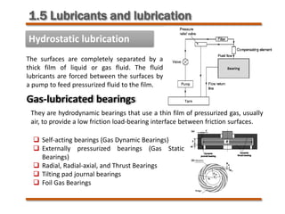
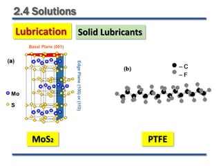
Lubrication Solid Lubricants
Molybdenum disulfide (MoS2) [Powder or PVD coating]
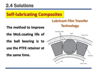
Polytetrafluoroethylene (PTFE)
Metals with low shear strength such as Lead (Pb)
Lamellar solids, Polymers, Metal salts, and Soft
metals
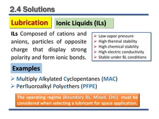
Examples](https://image.slidesharecdn.com/spacetribology2-230511145006-6473919a/85/Space-Tribology2-pdf-75-320.jpg)

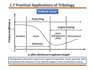
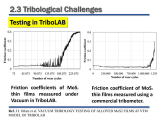
The document provides a comprehensive overview of tribology, including its definition, historical background, and its relevance in various applications such as space and engineering. It discusses the properties of tribo-materials, mechanisms of friction and wear, types of lubrication, and challenges in tribo-systems. Key topics also include the impact of operational conditions on tribological performance and the advancements in lubrication technologies.


