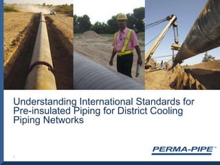
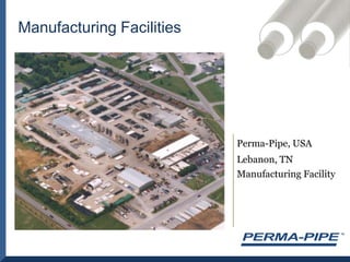
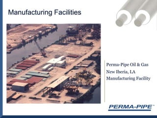
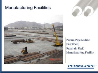
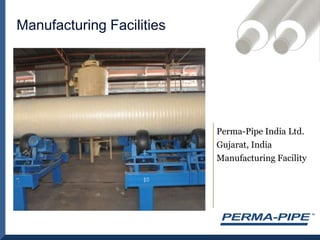
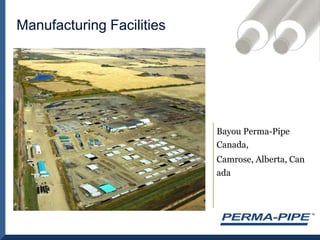
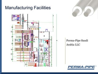
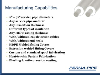
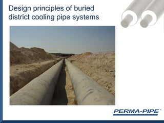
Understanding International Standards for Pre-insulated Piping for District Cooling Piping Networks1
About Perma-PipeDesign principles of buried district cooling systemsInternational StandardsDissecting a Pre-insulated PipeCasingEnd-SealsInsulationCarbon Steel Carrier PipesCorrosion ProtectionLeak Detection SystemsField Joint SystemsConclusionsContents
Perma-Pipe established in 1961 Ricwil established in 1910Division of MFRI, Inc.NASDAQ  traded company$ 200 + million / year revenuesPerma-PipeGlobal manufacturer & engineering company providing piping systems & solutions$100+ million / year revenuesDistrict Heating & Cooling, Environmental, Industrial, and Oil & Gas MarketsLargest supplier of pre-fabricated / pre-insulated piping systems in North America & the Middle EastInstallations all over the worldAbout Perma-Pipe
Perma-Pipe CredentialsHolds the Chairman position on the ASTM Task Group responsible for developing standardsfor pre-insulated piping standard for district heating & cooling.First member ofInternational District Energy Association (IDEA). Member since 1921.Products Certified to EN 253standards.Been supplying to the Middle East since 1975.Supplier of the worlds longest pre-insulated pipeline – 590 km from Rjaastan to GujaratProducts successfully in service for over 40 years!
Manufacturing FacilitiesPerma-Pipe, USALebanon, TN Manufacturing Facility
Manufacturing FacilitiesPerma-Pipe Oil & GasNew Iberia, LA Manufacturing Facility
Manufacturing FacilitiesPerma-Pipe Middle East (FZE)Fujairah, UAE Manufacturing Facility
Manufacturing FacilitiesPerma-Pipe India Ltd. Gujarat, India Manufacturing Facility
Manufacturing FacilitiesBayou Perma-Pipe Canada, Camrose, Alberta, Canada
Manufacturing FacilitiesPerma-Pipe Saudi Arabia LLC
2” – 72” service pipe diametersAny service pipe materialAny insulation thicknessDifferent types of insulationAny HDPE casing thicknessWith/without leak detection cablesWith/without end-sealsHDPE Molded fitting CoversExtrusion welded fitting CoversCustom and standard spool fabricationHeat-tracing System FabricationBlasting & anti-corrosion coatingManufacturing Capabilities
Design principles of buried district cooling pipe systems
Contraction/expansion of service pipeFriction between casing and soilVirtual anchors/restrained systemsPipe movementHoop stress of pipeStress analysis
When axial force from service pipe is less than the accumulated friction the pipe will be fully  restrained.SYSTEM LAY OUT PRINCIPLES:Cold installationPre-heated/pre-stressed systemsCompensated systems
Expansion/contraction of pipeExpansion/contraction absorbed by elbows or expansion loopsExpansion cushionsCompensators/contraction jointsCushions at branchesAnchors
EXPANSION CUSHIONSElastomeric foamClosed cellSoft/flexible
Hoop stress from internal pressureExample:10 bar system, 30” pipe, sch stdRestrained stressExample:Operating temperature 5˚C, installation temperature 35˚CΔT = 30˚CAccumulated stress
Bonding between pipe-foam-jacketBackfilling materialsPipe movement at branchesHoop stress is not the dominating stress factor Complex systemsFatigue of pipeStress analysis is “a must”Design and verifications
ExamplesProper installationPoor workman ship
International StandardsEuropean StandardsBackground PositivesQuality AssuranceStandardized System NegativesBased on all-case scenarioWritten for district heating NOT district coolingBased on cold & harsh European environment Limits innovation Over designed and adds unnecessary cost, especially for chilled water systemsThicker than required HDPE casing
North American StandardsBackgroundASTM Standard for insulated pipe is under final developmentNegativesAllows all service pipes. Some service pipes are not as adequate for the application as steel pipePositivesVarious pipe materialsDesigns are uniquely engineered to each project for innovative solutionsHolds the insulated piping manufacturer responsible for the recommended solutionsHDPE casing thickness engineered for project specific requirementsInternational Standards
Peeling back the layers of a Pre-Insulated Pipe  - Understanding the HDPE Casing
The outer casing has 2 main functions:Mechanical ProtectionDuring material handling at the plant and on-siteDuring freight & transportationVapor BarrierPreventing water ingress during installation due to trench floodingIsolating underground water during operationSignificantly reduces diffusion of the blowing agent gas from the PU cell structureUnderstanding the Function of the HDPE Casing
Why does EN 253 require thicker than required HDPE casing?Foaming is exothermic – heat deforms the casingEN standards written based on process limitations of the injection systemThin casing damaged during storage & transportation especially for larger diameters pipingPolitically difficult to change, even with new technology
HDPE Casing – How thick is thick enough?Soda Ash Project  in Colorado12” pipe, 50 mm insulation - 150 km Less than 2mm jacket thicknessBarmer to Salaya cross-country Pipeline (BSPL)Rajasthan to Gujarat, India 24” pipe , 90 mm insulation - 590 kmVarious rugged terrain  including desert, marsh-land and forestFollowed EN 253 quality standard but with 5 mm HDPE casingTypical jacket thickness for Western Canadian Oil & Gas market is 1.5 mmSupplied thousands of kilometers of thin wall jacket
Point Load TestSteel Rod (Penetrator) : 12.0mmMTS Machine Speed : 5.1mm/minAmbient Temperature : 24 CRelative Humidity : 52.9%Average Density of foam : 50 kg/m3HDPE Jacket thickness specimens tested: 3mm & 4 mmMeasured Peak Loads:  1516 – 1979 N
EN 253 vs. Recommended CasingThickness
Peeling back the layers of a Pre-Insulated Pipe  - Other Casing Materials
ApplicationsAbove-ground applicationsFire-retardant propertiesOptionsSpiral formed casingCigarette wrap casingsGI/Al Casing
ApplicationsAbove and Below-ground applicationsFire-retardant propertiesAdvantagesHigher TemperaturesHigher StrengthDisadvantage	Higher CostGRP Casing
Peeling back the layers of a Pre-Insulated Pipe - End Seal
HDPE End-Seal – A Water Spread Limiting SystemSeamless HDPE Wind-Down End SealMoisture contained to field joint or to one length of pipe
End Seal Certification TestPressure Vessel Gauge Reading Test pressure is 11 PSI  (76 KPa).Removing Test Specimen From Pressurized Testing Chamber
End Seal Certification TestCONCLUSION: No evidence of water . Ingression test establishing the functionality of a seamless end-seal.
Peeling back the layers of a Pre-Insulated Pipe  - Understanding the Bonding Layer
Bonding is required to design the system as “strain based” with virtual anchors (buried pipes).Load transfer from pipe to  insulation to jacket.Pipe, insulation and jacket move together as a unit.No water transfer longitudinal to the pipe.Why is Bonding Important?
Shear Strength TestEN253 Requirement is >0.12 MPa
Achieved minimum 0.15 MPa during testingPeeling back the layers of a Pre-Insulated Pipe  - Understanding Polyurethane Foam
Comparison of  Injection vs. Spray Applied PU FoamInjected PU foamMay have voidsNot concentricJacket may not bond to insulationInconsistent densityInconsistent compressive strengthInconsistent thermal conductivityPredetermined thickness incrementsHigher costDifficult inspection / lower qualitySprayed PU foamNo insulation voidsFully concentricJacket fully bonded to the insulationConsistent densityConsistent compressive strengthConsistent thermal conductivityPrecise thicknessLower costEasy inspection / higher quality
Understanding Polyurethane - DensitySelecting the right density is important to strike the best possible cost-effectiveness ratio. The higher the density, the higher the thermal conductivity. The higher the density the higher the compressive strength.The higher the density, the higher the cost!Current EN 253 does not specify density.
Understanding Polyurethane – Thermal Conductivity (K Value)      The k value is the most important parameter in determining the efficiency of the insulated piping system. This is what you pay for!     The thermal conductivity of insulation materials decreases as the temperature falls. Temperature increases on the other hand result in a minimal increase in thermal conductivity.      Aged k value is what should be considered in the design of an insulated piping system. It is important to note that all polyurethane insulations will age. The difference is the duration over which the insulation will age.
Thermal Conductivity vs. Density0.240.200.160.12Thermal Conductivity  (BTU-in/hr-ft2-oF)0                 2                 4                6                 8                 10Density (lbs/ft3)
Understanding Polyurethane - Compressive StrengthThis parameter is the second most important consideration for designing insulated piping systems.PERCEPTION: The HDPE Jacket provides the loading properties of the system.FACT: Compressive Strength of the foam provides the loading characteristics of the system.Soil loading determines the required compressive strength.
Polyurethane Compressive Strength
Understanding Polyurethane - Closed Cell ContentThis parameter determines the water absorption characteristics of the polyurethane foam.Every step and effort must be taken to keep water out of the system. Wet insulation is no insulation. Water is the dielectric for corrosionThe higher the closed cell content the slower the gas diffuses out of the foam and hence slower the aging.Note: Even though not listed in the revision changes this parameter was removed from latest version of EN 253. Previous EN 253 standards specified the requirement as 88%.
Polyurethane Foam – Blowing Agents K FactorThe insulation properties of rigid polyurethane foam are determined by blowing agents.Thermal conductivity of foam made with various blowing agents.
Average Thermal Conductivity vs. TemperatureHCFC 141b & HFC 245fa have much lower thermal conductivity than Cyclopentane(Data provided by Association of Home Appliances Manufacturers, AHAM, USA)
Average Aged Foam Thermal ConductivityFoam with HFC-245fa and R141b have lower K-Factors after aging than Cyclopentane.
Understanding Blowing Agents – Water Blown Foam (CO2)CO2 blown foam provides the worst thermal conductivity as compared to other blowing agents.CO2 has very small molecules that will diffuse into the air or into the cell walls and be replaced by Nitrogen molecules.The process of aging is hence the fastest in the case of CO2 blown foam.
Peeling back the layers of a Pre-Insulated Pipe  - Anti-Corrosion Epoxy Coating
Insulation is a very good anti-corrosion coating because of its excellent electrical insulation valueHowever, when wet, insulation no longer acts as a corrosion protection layerIf leak from outside the water will be very corrosiveSurface Preparation – Blasting to SA 2 ½, Epoxy CoatingCase Study: Princess Noura UniversityHeavy rains in Riyadh earlier this yearTrenches floodedWater entered hundreds of joints during constructionCorrosion Protection
Peeling back the layers of a Pre-Insulated Pipe  - Understanding Carbon Steel Pipes
Steel Service PipeDisadvantagesAdvantagesOD Corrosion: The insulated pipe must be installed dry and kept dry.
ID Corrosion: The water must be treated (non corrosive quality)Durable and ideal for higher pressure applicationsWelded construction - No risk of field joint leaksRelatively inexpensiveContractors are familiar with the welding and layout techniquesField joint weld quality can be verified with a variety of NDE methods  (x-ray, ultrasonic, magnetic particle)
Pipe Thickness ConsiderationsWater QualityWater quality used in the Middle East is not the same as what is used in EuropeWater is mostly made from desalinated seawater so level of chlorides may be higherLonger Delivery TimesMuch lower availability of BS and EN standard pipes as compared to ASTM standard pipes – manufactured by fewer mills.Thin walled pipe is not carried by Middle East pipe stockistsCorrosion Annual corrosion rate for steel must be calculated. Depends on O2  contentPipe Handling Thin wall pipe is lighter and hence may be easier to handleThin wall pipe is much easier to damage during storage, transportation and handling
Steel Service Pipe Wall Thickness – EN 253 vs. Standard Weight Pipe
Understanding Fitting Manufacturing Processes
FabricationFabrication done in-house by trained, tested and certified weldersMIG/TIG/SAW/GTAW/GMAW/FCAW/Plasma Cutting/Victaulic GroovingAll required testing facilities on siteUltrasonic Testing (UT)Radiography Testing (RT/X-Ray)Magnetic Particle Testing(MT)Die Penetrant Testing(PT)
Seamless Molded Fitting CoversNo welds or seams
High quality
Lower costs
Ease of fabrication
Available for Ts and Elbows Leak Detection Systems
Why use a Leak Detection System?Is it required  can leaks be detected in other ways?To avoid corrosion?To avoid excessive  loss of water?To avoid increased heat loss/gain?
Resistance (Nordic system)TDR /Capacitance system (Time Domain Reflectometry)Mechanical wiresPressure dropHeat sensitive camera (thermo graphic camera)Visual monitoringLeak Detection Principles
Important Features in Leak Detection SystemsEase of installationEase of operationConnection to BMSAccuracy in locating leaksMonitor leaksFinding multiple leaksFalse alarmsPrice
Working PrinciplesNordic system	Measuring resistance between 2 copper wiresElectrons will travel through liquid and resistance will dropWorks only in conductive liquidsTDR systemSend energy pulses in cables reading the reflections of energyDrop in energy reflection will show leakWill work with all liquids
Leak Detection ComparisonNordic system	Will detect only one leakSensitive to moistureProne to give false alarmsDifficult to find leaks (in-accurate)One wet joint will render the system useless.TDRCan detect multiple leaksLess sensitive to moisture but will sense waterNo false alarmsEasy to find leaksVery accurate indications of where the leak isMapping technology available
Time Domain ReflectometryPAL-ATTDR is a cable measuring technology related to sonar and radar.  By sending energy pulses down the center conductor of a coaxial cable and measuring the reflected energy a map can be stored of the cable and monitored for change.  When change occurs the type of alarm and its location is displayed on the panel.
TDR Trace of Dry Cable
TDR Trace with Leak Detected
TDRTrace of System with Wet Cable
TDR Trace Showing Growing Leak
Map 3 Response
Second Leak Detected
Monitoring with Liquid onthe Cable
Break Detected
Short Detected
Where does Perm-Alert differ from other systems?Mapping of reflection Multiple leaks can be found and monitoredReduced risk of false alarmWill give leak and location of leak immediatelySet point follows the actual TDR response not as a fixed valueMore sensitive than other TDR systemsSoftware will show location of leak on BMS
Palcom SoftwarePAL-AT and LiquidWatchPalcom allows remote control of up to 254 panels with the ability to review TDR traces, review the history of each unit and to pull down a CAD drawing for each system for location of leaks, breaks, shorts or probe activations.
Field Joint Systems
Application methodTubularWrap aroundSealent methodMastic/hot melt sealed WeldedMaterial typeCross linkedNon cross linkedField Joint Systems
Wrap Around Heat Shrink SleevesWrap Around Shrink Sleeves Can Be Installed After WeldingPolyolyfin sheet, irradiated, stretched and mastic/hotmelt is then applied for sealingApplied by wrapping around the insulated joint and returning the sleeve to its original dimensions by the application of heat utilized from a torchFeaturesCan be supplied as double sealedDoes not require special tools/machineryEasy to inspectEasy to repairDoes not require extensive training –easy to apply

Soren kjaer, perma pipe

  • 1.
    Understanding International Standardsfor Pre-insulated Piping for District Cooling Piping Networks1
  • 2.
    About Perma-PipeDesign principlesof buried district cooling systemsInternational StandardsDissecting a Pre-insulated PipeCasingEnd-SealsInsulationCarbon Steel Carrier PipesCorrosion ProtectionLeak Detection SystemsField Joint SystemsConclusionsContents
  • 3.
    Perma-Pipe established in1961 Ricwil established in 1910Division of MFRI, Inc.NASDAQ traded company$ 200 + million / year revenuesPerma-PipeGlobal manufacturer & engineering company providing piping systems & solutions$100+ million / year revenuesDistrict Heating & Cooling, Environmental, Industrial, and Oil & Gas MarketsLargest supplier of pre-fabricated / pre-insulated piping systems in North America & the Middle EastInstallations all over the worldAbout Perma-Pipe
  • 4.
    Perma-Pipe CredentialsHolds theChairman position on the ASTM Task Group responsible for developing standardsfor pre-insulated piping standard for district heating & cooling.First member ofInternational District Energy Association (IDEA). Member since 1921.Products Certified to EN 253standards.Been supplying to the Middle East since 1975.Supplier of the worlds longest pre-insulated pipeline – 590 km from Rjaastan to GujaratProducts successfully in service for over 40 years!
  • 5.
  • 6.
    Manufacturing FacilitiesPerma-Pipe Oil& GasNew Iberia, LA Manufacturing Facility
  • 7.
    Manufacturing FacilitiesPerma-Pipe MiddleEast (FZE)Fujairah, UAE Manufacturing Facility
  • 8.
    Manufacturing FacilitiesPerma-Pipe IndiaLtd. Gujarat, India Manufacturing Facility
  • 9.
    Manufacturing FacilitiesBayou Perma-PipeCanada, Camrose, Alberta, Canada
  • 10.
  • 11.
    2” – 72”service pipe diametersAny service pipe materialAny insulation thicknessDifferent types of insulationAny HDPE casing thicknessWith/without leak detection cablesWith/without end-sealsHDPE Molded fitting CoversExtrusion welded fitting CoversCustom and standard spool fabricationHeat-tracing System FabricationBlasting & anti-corrosion coatingManufacturing Capabilities
  • 12.
    Design principles ofburied district cooling pipe systems
  • 13.
    Contraction/expansion of servicepipeFriction between casing and soilVirtual anchors/restrained systemsPipe movementHoop stress of pipeStress analysis
  • 14.
    When axial forcefrom service pipe is less than the accumulated friction the pipe will be fully restrained.SYSTEM LAY OUT PRINCIPLES:Cold installationPre-heated/pre-stressed systemsCompensated systems
  • 15.
    Expansion/contraction of pipeExpansion/contractionabsorbed by elbows or expansion loopsExpansion cushionsCompensators/contraction jointsCushions at branchesAnchors
  • 16.
  • 17.
    Hoop stress frominternal pressureExample:10 bar system, 30” pipe, sch stdRestrained stressExample:Operating temperature 5˚C, installation temperature 35˚CΔT = 30˚CAccumulated stress
  • 18.
    Bonding between pipe-foam-jacketBackfillingmaterialsPipe movement at branchesHoop stress is not the dominating stress factor Complex systemsFatigue of pipeStress analysis is “a must”Design and verifications
  • 19.
  • 20.
    International StandardsEuropean StandardsBackgroundPositivesQuality AssuranceStandardized System NegativesBased on all-case scenarioWritten for district heating NOT district coolingBased on cold & harsh European environment Limits innovation Over designed and adds unnecessary cost, especially for chilled water systemsThicker than required HDPE casing
  • 21.
    North American StandardsBackgroundASTMStandard for insulated pipe is under final developmentNegativesAllows all service pipes. Some service pipes are not as adequate for the application as steel pipePositivesVarious pipe materialsDesigns are uniquely engineered to each project for innovative solutionsHolds the insulated piping manufacturer responsible for the recommended solutionsHDPE casing thickness engineered for project specific requirementsInternational Standards
  • 22.
    Peeling back thelayers of a Pre-Insulated Pipe - Understanding the HDPE Casing
  • 23.
    The outer casinghas 2 main functions:Mechanical ProtectionDuring material handling at the plant and on-siteDuring freight & transportationVapor BarrierPreventing water ingress during installation due to trench floodingIsolating underground water during operationSignificantly reduces diffusion of the blowing agent gas from the PU cell structureUnderstanding the Function of the HDPE Casing
  • 24.
    Why does EN253 require thicker than required HDPE casing?Foaming is exothermic – heat deforms the casingEN standards written based on process limitations of the injection systemThin casing damaged during storage & transportation especially for larger diameters pipingPolitically difficult to change, even with new technology
  • 25.
    HDPE Casing –How thick is thick enough?Soda Ash Project in Colorado12” pipe, 50 mm insulation - 150 km Less than 2mm jacket thicknessBarmer to Salaya cross-country Pipeline (BSPL)Rajasthan to Gujarat, India 24” pipe , 90 mm insulation - 590 kmVarious rugged terrain including desert, marsh-land and forestFollowed EN 253 quality standard but with 5 mm HDPE casingTypical jacket thickness for Western Canadian Oil & Gas market is 1.5 mmSupplied thousands of kilometers of thin wall jacket
  • 26.
    Point Load TestSteelRod (Penetrator) : 12.0mmMTS Machine Speed : 5.1mm/minAmbient Temperature : 24 CRelative Humidity : 52.9%Average Density of foam : 50 kg/m3HDPE Jacket thickness specimens tested: 3mm & 4 mmMeasured Peak Loads: 1516 – 1979 N
  • 27.
    EN 253 vs.Recommended CasingThickness
  • 28.
    Peeling back thelayers of a Pre-Insulated Pipe - Other Casing Materials
  • 29.
  • 30.
    ApplicationsAbove and Below-groundapplicationsFire-retardant propertiesAdvantagesHigher TemperaturesHigher StrengthDisadvantage Higher CostGRP Casing
  • 31.
    Peeling back thelayers of a Pre-Insulated Pipe - End Seal
  • 32.
    HDPE End-Seal –A Water Spread Limiting SystemSeamless HDPE Wind-Down End SealMoisture contained to field joint or to one length of pipe
  • 33.
    End Seal CertificationTestPressure Vessel Gauge Reading Test pressure is 11 PSI (76 KPa).Removing Test Specimen From Pressurized Testing Chamber
  • 34.
    End Seal CertificationTestCONCLUSION: No evidence of water . Ingression test establishing the functionality of a seamless end-seal.
  • 35.
    Peeling back thelayers of a Pre-Insulated Pipe - Understanding the Bonding Layer
  • 36.
    Bonding is requiredto design the system as “strain based” with virtual anchors (buried pipes).Load transfer from pipe to insulation to jacket.Pipe, insulation and jacket move together as a unit.No water transfer longitudinal to the pipe.Why is Bonding Important?
  • 37.
    Shear Strength TestEN253Requirement is >0.12 MPa
  • 38.
    Achieved minimum 0.15MPa during testingPeeling back the layers of a Pre-Insulated Pipe - Understanding Polyurethane Foam
  • 39.
    Comparison of Injection vs. Spray Applied PU FoamInjected PU foamMay have voidsNot concentricJacket may not bond to insulationInconsistent densityInconsistent compressive strengthInconsistent thermal conductivityPredetermined thickness incrementsHigher costDifficult inspection / lower qualitySprayed PU foamNo insulation voidsFully concentricJacket fully bonded to the insulationConsistent densityConsistent compressive strengthConsistent thermal conductivityPrecise thicknessLower costEasy inspection / higher quality
  • 40.
    Understanding Polyurethane -DensitySelecting the right density is important to strike the best possible cost-effectiveness ratio. The higher the density, the higher the thermal conductivity. The higher the density the higher the compressive strength.The higher the density, the higher the cost!Current EN 253 does not specify density.
  • 41.
    Understanding Polyurethane –Thermal Conductivity (K Value) The k value is the most important parameter in determining the efficiency of the insulated piping system. This is what you pay for! The thermal conductivity of insulation materials decreases as the temperature falls. Temperature increases on the other hand result in a minimal increase in thermal conductivity. Aged k value is what should be considered in the design of an insulated piping system. It is important to note that all polyurethane insulations will age. The difference is the duration over which the insulation will age.
  • 42.
    Thermal Conductivity vs.Density0.240.200.160.12Thermal Conductivity (BTU-in/hr-ft2-oF)0 2 4 6 8 10Density (lbs/ft3)
  • 43.
    Understanding Polyurethane -Compressive StrengthThis parameter is the second most important consideration for designing insulated piping systems.PERCEPTION: The HDPE Jacket provides the loading properties of the system.FACT: Compressive Strength of the foam provides the loading characteristics of the system.Soil loading determines the required compressive strength.
  • 44.
  • 45.
    Understanding Polyurethane -Closed Cell ContentThis parameter determines the water absorption characteristics of the polyurethane foam.Every step and effort must be taken to keep water out of the system. Wet insulation is no insulation. Water is the dielectric for corrosionThe higher the closed cell content the slower the gas diffuses out of the foam and hence slower the aging.Note: Even though not listed in the revision changes this parameter was removed from latest version of EN 253. Previous EN 253 standards specified the requirement as 88%.
  • 46.
    Polyurethane Foam –Blowing Agents K FactorThe insulation properties of rigid polyurethane foam are determined by blowing agents.Thermal conductivity of foam made with various blowing agents.
  • 47.
    Average Thermal Conductivityvs. TemperatureHCFC 141b & HFC 245fa have much lower thermal conductivity than Cyclopentane(Data provided by Association of Home Appliances Manufacturers, AHAM, USA)
  • 48.
    Average Aged FoamThermal ConductivityFoam with HFC-245fa and R141b have lower K-Factors after aging than Cyclopentane.
  • 49.
    Understanding Blowing Agents– Water Blown Foam (CO2)CO2 blown foam provides the worst thermal conductivity as compared to other blowing agents.CO2 has very small molecules that will diffuse into the air or into the cell walls and be replaced by Nitrogen molecules.The process of aging is hence the fastest in the case of CO2 blown foam.
  • 50.
    Peeling back thelayers of a Pre-Insulated Pipe - Anti-Corrosion Epoxy Coating
  • 51.
    Insulation is avery good anti-corrosion coating because of its excellent electrical insulation valueHowever, when wet, insulation no longer acts as a corrosion protection layerIf leak from outside the water will be very corrosiveSurface Preparation – Blasting to SA 2 ½, Epoxy CoatingCase Study: Princess Noura UniversityHeavy rains in Riyadh earlier this yearTrenches floodedWater entered hundreds of joints during constructionCorrosion Protection
  • 52.
    Peeling back thelayers of a Pre-Insulated Pipe - Understanding Carbon Steel Pipes
  • 53.
    Steel Service PipeDisadvantagesAdvantagesODCorrosion: The insulated pipe must be installed dry and kept dry.
  • 54.
    ID Corrosion: Thewater must be treated (non corrosive quality)Durable and ideal for higher pressure applicationsWelded construction - No risk of field joint leaksRelatively inexpensiveContractors are familiar with the welding and layout techniquesField joint weld quality can be verified with a variety of NDE methods (x-ray, ultrasonic, magnetic particle)
  • 55.
    Pipe Thickness ConsiderationsWaterQualityWater quality used in the Middle East is not the same as what is used in EuropeWater is mostly made from desalinated seawater so level of chlorides may be higherLonger Delivery TimesMuch lower availability of BS and EN standard pipes as compared to ASTM standard pipes – manufactured by fewer mills.Thin walled pipe is not carried by Middle East pipe stockistsCorrosion Annual corrosion rate for steel must be calculated. Depends on O2 contentPipe Handling Thin wall pipe is lighter and hence may be easier to handleThin wall pipe is much easier to damage during storage, transportation and handling
  • 56.
    Steel Service PipeWall Thickness – EN 253 vs. Standard Weight Pipe
  • 57.
  • 58.
    FabricationFabrication done in-houseby trained, tested and certified weldersMIG/TIG/SAW/GTAW/GMAW/FCAW/Plasma Cutting/Victaulic GroovingAll required testing facilities on siteUltrasonic Testing (UT)Radiography Testing (RT/X-Ray)Magnetic Particle Testing(MT)Die Penetrant Testing(PT)
  • 59.
    Seamless Molded FittingCoversNo welds or seams
  • 60.
  • 61.
  • 62.
  • 63.
    Available for Tsand Elbows Leak Detection Systems
  • 64.
    Why use aLeak Detection System?Is it required can leaks be detected in other ways?To avoid corrosion?To avoid excessive loss of water?To avoid increased heat loss/gain?
  • 65.
    Resistance (Nordic system)TDR/Capacitance system (Time Domain Reflectometry)Mechanical wiresPressure dropHeat sensitive camera (thermo graphic camera)Visual monitoringLeak Detection Principles
  • 66.
    Important Features inLeak Detection SystemsEase of installationEase of operationConnection to BMSAccuracy in locating leaksMonitor leaksFinding multiple leaksFalse alarmsPrice
  • 67.
    Working PrinciplesNordic system Measuringresistance between 2 copper wiresElectrons will travel through liquid and resistance will dropWorks only in conductive liquidsTDR systemSend energy pulses in cables reading the reflections of energyDrop in energy reflection will show leakWill work with all liquids
  • 68.
    Leak Detection ComparisonNordicsystem Will detect only one leakSensitive to moistureProne to give false alarmsDifficult to find leaks (in-accurate)One wet joint will render the system useless.TDRCan detect multiple leaksLess sensitive to moisture but will sense waterNo false alarmsEasy to find leaksVery accurate indications of where the leak isMapping technology available
  • 69.
    Time Domain ReflectometryPAL-ATTDRis a cable measuring technology related to sonar and radar. By sending energy pulses down the center conductor of a coaxial cable and measuring the reflected energy a map can be stored of the cable and monitored for change. When change occurs the type of alarm and its location is displayed on the panel.
  • 70.
    TDR Trace ofDry Cable
  • 71.
    TDR Trace withLeak Detected
  • 72.
    TDRTrace of Systemwith Wet Cable
  • 73.
    TDR Trace ShowingGrowing Leak
  • 74.
  • 75.
  • 76.
  • 77.
  • 78.
  • 79.
    Where does Perm-Alertdiffer from other systems?Mapping of reflection Multiple leaks can be found and monitoredReduced risk of false alarmWill give leak and location of leak immediatelySet point follows the actual TDR response not as a fixed valueMore sensitive than other TDR systemsSoftware will show location of leak on BMS
  • 80.
    Palcom SoftwarePAL-AT andLiquidWatchPalcom allows remote control of up to 254 panels with the ability to review TDR traces, review the history of each unit and to pull down a CAD drawing for each system for location of leaks, breaks, shorts or probe activations.
  • 81.
  • 82.
    Application methodTubularWrap aroundSealentmethodMastic/hot melt sealed WeldedMaterial typeCross linkedNon cross linkedField Joint Systems
  • 83.
    Wrap Around HeatShrink SleevesWrap Around Shrink Sleeves Can Be Installed After WeldingPolyolyfin sheet, irradiated, stretched and mastic/hotmelt is then applied for sealingApplied by wrapping around the insulated joint and returning the sleeve to its original dimensions by the application of heat utilized from a torchFeaturesCan be supplied as double sealedDoes not require special tools/machineryEasy to inspectEasy to repairDoes not require extensive training –easy to apply

Editor's Notes

  • #37 (verbal: load angel can be increased from 90 to 180˚)