This technical bulletin emphasizes the importance of selecting proper insulation materials and vapor barriers in refrigeration applications to optimize performance and reduce costs. Key considerations include thermal conductivity and water vapor transmission rates, as they significantly affect energy efficiency and overall operational costs. The bulletin also discusses the advantages of specific insulation types, such as Dyplast's ISO-C1® polyisocyanurate, and the critical role of vapor barriers in protecting insulants from moisture intrusion.
![Page 1 of 6
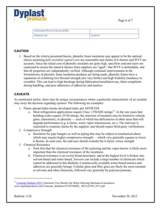
TECHNICAL BULLETIN 11281
Mechanical Insulation
In Typical Refrigeration Applications
PURPOSE
As operating temperatures of mechanical equipment and piping systems drop, increased diligence must
be exercised to optimize the insulation system’s performance and mitigate risks of future deterioration.
When specifying and installing an insulation system for pipes or equipment operating at refrigerant
temperatures (e.g. -70°F to 32°F) cutting corners or rationalizing compromises is imprudent since the
operating costs and risks far outweigh any reduced capital costs; and it is important to note that the best
systems are typically not the most expensive systems.
The purpose of this Customer Bulletin is to simplify what can be often perceived as a complicated
process by offering objective information on the most important step: the selection of insulants and
vapor barriers. The repercussions of a poor selection at this stage cannot be mitigated during later steps.
A comprehensive discussion of the various physical properties of insulation alternatives is beyond the
scope of this bulletin - - and fortunately such a detailed analysis is unnecessary. In fact, the big picture
too often gets lost in the debate over issues of little impact.
It is important to also note that “what is not said” can be more important than “what is said”; thus we
strive for full disclosure while also striving for brevity. As always, if the reader of this Bulletin believes
we have erred or misrepresented facts, we welcome suggestions.
SUMMARY
Manufacturers and suppliers of mechanical insulation and system accessories typically provide
datasheets listing a host of physical properties. This Bulletin offers that the importance of thermal
conductivity (k-factor2,3) and water vapor transmission (WVT4) of the insulant typically far outweighs
the impact of other physical properties. Thus refrigeration system specifiers, engineers, procurement
managers, contractors and owners should focus heavily on these two physical properties when
comparing alternative insulation materials.
[We note a caveat, of course, that there may be specific requirements for a particular application that
may otherwise influence the decision - - discussed later in this Bulletin.]
1
An Update to Customer Bulletin 0411.
2
Simplified, the k-factor (thermal conductivity) is the measure of heat that passes through one square foot of material that is 1 inch thick in
an hour per unit temperature difference. The lower the K value, the better the insulation. C-factor is the k-factor divided by the thickness of
the insulation material. The R-factor per inch can be determined by R=1/k. The higher the R factor, the better the insulation.
3
The issue of aged versus initial k-factors is addressed later in this document.
4
The Water Vapor Transmission Rate of a material is referred to as its permeability, stated in perm-inches; independent of the materials'
thickness. Dividing the permeability of a material by its thickness gives the materials' permeance, stated in perms. ASTM E96 measures a
material’s rate of Water Vapor Transmission per unit area per unit of vapor pressure differential under test conditions, expressed as perm-
inches (grain/hr·ft2·in Hg·in) of thickness.](https://image.slidesharecdn.com/customerbulletin0411-130411131651-phpapp02/85/Technical-Bulletin-1128A-Mechanical-Insulation-In-Typical-Refrigeration-Applications-1-320.jpg)
![Page 1 of 6
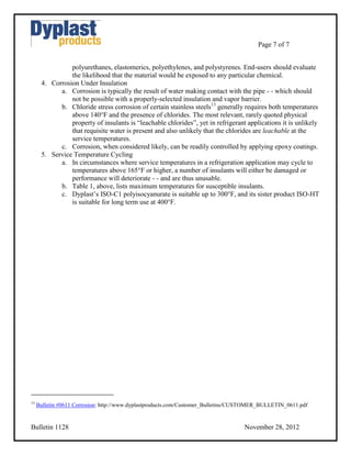
TECHNICAL BULLETIN 11281
Mechanical Insulation
In Typical Refrigeration Applications
PURPOSE
As operating temperatures of mechanical equipment and piping systems drop, increased diligence must
be exercised to optimize the insulation system’s performance and mitigate risks of future deterioration.
When specifying and installing an insulation system for pipes or equipment operating at refrigerant
temperatures (e.g. -70°F to 32°F) cutting corners or rationalizing compromises is imprudent since the
operating costs and risks far outweigh any reduced capital costs; and it is important to note that the best
systems are typically not the most expensive systems.
The purpose of this Customer Bulletin is to simplify what can be often perceived as a complicated
process by offering objective information on the most important step: the selection of insulants and
vapor barriers. The repercussions of a poor selection at this stage cannot be mitigated during later steps.
A comprehensive discussion of the various physical properties of insulation alternatives is beyond the
scope of this bulletin - - and fortunately such a detailed analysis is unnecessary. In fact, the big picture
too often gets lost in the debate over issues of little impact.
It is important to also note that “what is not said” can be more important than “what is said”; thus we
strive for full disclosure while also striving for brevity. As always, if the reader of this Bulletin believes
we have erred or misrepresented facts, we welcome suggestions.
SUMMARY
Manufacturers and suppliers of mechanical insulation and system accessories typically provide
datasheets listing a host of physical properties. This Bulletin offers that the importance of thermal
conductivity (k-factor2,3) and water vapor transmission (WVT4) of the insulant typically far outweighs
the impact of other physical properties. Thus refrigeration system specifiers, engineers, procurement
managers, contractors and owners should focus heavily on these two physical properties when
comparing alternative insulation materials.
[We note a caveat, of course, that there may be specific requirements for a particular application that
may otherwise influence the decision - - discussed later in this Bulletin.]
1
An Update to Customer Bulletin 0411.
2
Simplified, the k-factor (thermal conductivity) is the measure of heat that passes through one square foot of material that is 1 inch thick in
an hour per unit temperature difference. The lower the K value, the better the insulation. C-factor is the k-factor divided by the thickness of
the insulation material. The R-factor per inch can be determined by R=1/k. The higher the R factor, the better the insulation.
3
The issue of aged versus initial k-factors is addressed later in this document.
4
The Water Vapor Transmission Rate of a material is referred to as its permeability, stated in perm-inches; independent of the materials'
thickness. Dividing the permeability of a material by its thickness gives the materials' permeance, stated in perms. ASTM E96 measures a
material’s rate of Water Vapor Transmission per unit area per unit of vapor pressure differential under test conditions, expressed as perm-
inches (grain/hr·ft2·in Hg·in) of thickness.](https://image.slidesharecdn.com/customerbulletin0411-130411131651-phpapp02/75/Technical-Bulletin-1128A-Mechanical-Insulation-In-Typical-Refrigeration-Applications-1-2048.jpg)