SlideShare a Scribd company logo
1 of 29
FABRICATION OF SOLAR GRASS CUTTER
1
CHAPTER 1
INTRODUCTION
Nowadays pollution is a major issue for whole world. Pollution is manmade and can be seen
in own homes, industries, and power plants. In case Gas powered lawn mowers due to the
emission of gases it is responsible for pollution. Also the cost of fuel is increasing hence it is
not efficient and battery type equipment is also extra cost of power. So the Solar powered
lawn cutters are introduced. Solar powered lawn mower can be described as the application
of solar energy to power an electric motor which in turn rotates a blade which does the
mowing of a lawn. Solar energy is the renewable energy.
Grass cutter or lawn mowing with a standard motor powered lawn mower is an
inconvenience, and no one takes pleasure in it. Cutting grass cannot be easily accomplished
by elderly, younger, or disabled people. Motor powered push lawn mowers and riding
lawnmowers create noise pollution due to the loud engine, and local air pollution due to the
combustion in the engine. Also, a motor powered engine requires periodic maintenance
such as changing the engine oil. Even though electric lawn mowers are environmentally
friendly, they too can be an inconvenience. Along with motor powered lawn mowers,
electric lawn mowersare also hazardous and cannot be easily used by all. Also, if the electric
lawn mower is corded,mowing could prove to be problematic and dangerous. The self-
propelling electric remotecontrol lawn mower is a lawn mower that has remote control
capability. This prototype is robotic user friendly, cost efficient, safe to use, efficient to use,
and environmentally friendly. Itcan save significantly on labor costs.
Fig: SOLAR GRASS CUTTER
FABRICATION OF SOLAR GRASS CUTTER
2
CHAPTER-2
LITERATURE SURVEY
2.1OBJECTIVE
For the manufacturing of a solar grass cutter we referred various literature, papers etc. The
review of previous method used given below: In this lawn mower uses an solar based energy
source, which is easier to use, more advantageous comparing to other energy source
especially for gas based source of power .But our lawn cutter is based on solar because this
energy is a renewable energy source and it is easy to work. So we made solar powered
lawnmower.
In today's climate of growing energy needs and increasing environmental concern,
alternatives to the use of non-renewable and polluting fossil fuels have to be investigated.
One such alternative is solar energy. In this solar based lawn mower, the advantage of
powering a lawn mower by solar rather than by gasoline is mainly ecological. We
manufactured this lawn cutter because it is very easy method and many overcome
produced from this type lawn cutter.
The self-powered objective is to come up with a mower that is portable, durable, easy to
operate and maintain. It also aims to design a self-powered mower of electrical source; a
cordless electric lawn mower. The heart of the machine is a battery powered dc electric
motor. It is also useful method for our lawn mower. It is similar to our lawn cutter using
display and keypad.
The present technology commonly used for trimming the grass is by using the manually
handle device. In this project we have automated the machine for trimming the grass. The
device consists of linear blade which is operated with the help of the motor the power
supply for the motor is by using battery. The battery can be charge by using power supply
and solar panel.
2.2 HISTORY
The first lawn mower was invented by Edwin Budding in 1830 just outside Stroud, in
Gloucestershire, England. Bedding’s mower was designed primarily to cut the grass on
sports grounds and extensive gardens, as a superior alternative to the scythe, and was
granted a British patent on August 31, 1830.
Bedding’s first machine was 19 inches (480 mm) wide with a frame made of wrought iron.
The mower was pushed from behind.
Cast iron gear wheels transmitted power from the rear roller to the cutting cylinder,
allowing the rear roller to drive the knives on the cutting cylinder; the ratio was 16:1.
Another roller placed between the cutting cylinder and the main or land roller could be
raised or lowered to alter the height of cut. The grass clippings were hurled forward into a
tray-like box. It was soon realized, however, that an extra handle was needed in front to
help pull the machine along. Overall, these machines were remarkably similar to modern
mowers.
Two of the earliest Budding machines sold went to Regent's Park Zoological Gardens in
London and the Oxford Colleges. In an agreement between John Ferrabee and Edwin
Budding dated May 18, 1830, Ferrabee paid the costs of enlarging the small blades,
obtained letters of patent and acquired rights to manufacture, sell and license other
manufacturers in the production of lawn mowers. Without patent, Budding and Ferrabee
were shrewd enough to allow other companies to build copies of their mower under license,
FABRICATION OF SOLAR GRASS CUTTER
3
the most successful of these being Ransoms of Ipswich, which began making mowers as
early as 1832
Fig: An early cylinder reel mower
His machine was the catalyst for the preparation of modern-style sporting ovals, playing
fields (pitches), grass courts, etc. This led to the codification of modern rules for many
sports, including for football, lawn bowls, lawn tennis and others
From the late nineteenth century through the middle of the twentieth century, DC-to-AC
power conversion was accomplished using rotary converters or motor-generator sets (M-G
sets). In the early twentieth century, vacuum tubes and gas filled tubes began to be used as
switches in inverter circuits. The most widely used type of tube was the thyratron.
The origins of electromechanical inverters explain the source of the term inverter. Early AC-
to-DC converters used an induction or synchronous AC motor direct-connected to a
generator (dynamo) so that the generator's commentator reversed its connections at
exactly the right moments to produce DC. A later development is the synchronous
converter, in which the motor and generator windings are combined into one armature,
with slip rings at one end and a commentator at the other and only one field frame.
The result with either is AC-in, DC-out. With an M-G set, the DC can be considered to be
separately generated from the AC; with a synchronous converter, in a certain sense it can be
considered to be "mechanically rectified AC". Given the right auxiliary and control
equipment, an M-G set or rotary converter can be "run backwards", converting DC to AC.
Hence an inverter is an inverted converter.
2.3 FURTHER IMPROVEMENTS
It took ten more years and further innovations to create a machine that could be drawn by
animals, and sixty years before a steam-powered lawn mower was built.
In the 1850s, Thomas Green & Son of Leeds introduced a mower called the SilensMessor
(meaning silent cutter), which used a chain to transmit power from the rear roller to the
cutting cylinder. These machines were lighter and quieter than the gear driven machines
that preceded them, although they were slightly more expensive. The rise in popularity of
lawn sports helped prompt the spread of the invention. Lawn mowers became a more
efficient alternative to the scythe and domesticated grazing animals.
Manufacture of lawn mowers took off in the 1860s. By 1862, Ferrabee's company was
making eight models in various roller sizes. He manufactured over 5000 machines until
production ceased in 1863. The first grass boxes were flat trays but took their present shape
in the 1860s. James Sumner of Lancashire patented the first steam-powered lawn mower in
1893.
FABRICATION OF SOLAR GRASS CUTTER
4
Fig: Commercial lawn mower
Manufacture of lawn mowers took off in the 1860s. By 1862, Ferrabee's company was
making eight models in various roller sizes. He manufactured over 5000 machines until
production ceased in 1863. The first grass boxes were flat trays but took their present shape
in the 1860s. James Sumner of Lancashire patented the first steam-powered lawn mower in
1893.
The first United States patent for a reel lawn mower was granted to Amariah Hills on
January 12, 1868. In 1870, Elwood McGuire of Richmond, Indiana designed a human-pushed
lawn mower, which was very lightweight and a commercial success.
John Burr patented an improved rotary-blade lawn mower in 1899, with the wheel
placement altered for better performance. Amariah Hills went on to found the Archimedean
Lawn Mower Co. in 1871.
In the United States, gasoline powered lawn mowers were first manufactured in 1914 by
Ideal Power Mower Co. of Lansing, Michigan, based on a patent by Ransom E. Olds. Ideal
Power Mower also introduced the world's first self-propelled, riding lawn tractor in 1922,
known as the "Triplex."
The roller-drive lawn mower has changed very little since around 1930. Gang mowers, those
with multiple sets of blades, were built in the United States in 1919 by the Worthington
Mower Company.
2.4 ROTARY MOWERS
Rotary mowers were not developed until engines were small enough and powerful enough
to run the blades at sufficient speed. Many people experimented with rotary blade mowers
in the late 1920s and early 1930s, and Power Specialties Ltd. introduced a gasoline-powered
rotary mower. KutKwick replaced the saw blade of the "Pulp Saw" with a double-edged
blade and a cutter deck, converting the "Pulp Saw" into the first ever out-front rotary
mower.
One company that produced rotary mowers commercially was the Australian Victa
company, starting in 1952. Its mowers were lighter and easier to use than similar ones that
had come before. The first Victa mowers were made at Mort lake, an inner suburb of
Sydney, by local resident Mervyn Victor Richardson. He made his first model out of scrap in
his garage and then moved to a shed behind St Mary's Church of England, where the first
Victa mowers were manufactured, going on sale on 20 September 1952. The new company,
Victa Mowers Pty Ltd, was incorporated on 13 February 1953.
FABRICATION OF SOLAR GRASS CUTTER
5
Fig: Rotary mowers
The venture was so successful that by 1958 the company moved to much larger
premises in Parramatta Road, Concord, and then to Milperra, by which time the mower
incorporated an engine, designed and manufactured by Victa, which was specially suitable
for mowing, rather than employing a general-purpose engine.[12] Two Victa mowers, from
1958 and 1968 respectively, are held in the collection of the National Museum of Australia.
The Victa mower is regarded as something of an Australian icon, appearing an masse, in
simulated form, at the opening of the Sydney Olympic Games in 2000
2.5 SOLAR GRASS CUTTER
The lawn mower or grass cutter is made up of a three motor, a battery, blades, and a link
mechanism. The power and charging system comprises of an alternator which charges the
battery while in operation. The D.C. motors forms the heart of the machine and provides the
driving force for the blades and rear wheels. This is achieved by the combined effect of
mechanical action of the cutting blades and the forward thrust of the mower. The system is
powered by an electrical switch which completes the circuit comprising the in DC motor and
the battery. The IR senor is finding the path to avoid the obstacles and machine damage.
The shaft fitting mechanism with which the height of cut is altered.
Solar power as an energy source will address a number of issues that standard internal
combustion engine mowers do not. An electric grass cutter with a solar charger will be
easier to use. There is no messy dangerous gasoline to deal with Most importantly it
eliminates the emissions of an internal combustion mower. A lawn mower is a device which
by means of one or more revolving blades issued to cutgrass or other plants to an even
length. Lawnmowers employing a blade that rotates about a vertical axis are known as
rotary mowers, while those employing a blade assembly that rotates about a horizontal axis
are known as cylinder or reel mowers.
Solar grass cutter are based on the use of small but powerful engine that provides
enough torque to spin a very sharp horizontal blade that cuts the grass upon contact. The
blade is located in the deck that prevents grass from flying all over the place when struck. In
most cases, the motor is situated at the top of the deck, which is usually mounted on four
wheels. There is also a bag connected to the deck that is used to collect cut grasses the
opinion that lawnmowers must be designed to reduce pollutions generated than at present.
FABRICATION OF SOLAR GRASS CUTTER
6
Solar grass cutter
It uses the photovoltaic panel to generate the energy needed to power the mower. It is
assumed that a lawnmower using solar as the energy source will address a number of issues
that the standard internal combustion engine and electric motors lawn mowers do not. A
lawnmower with solar energy will be easier to use, it eliminates down time by frequent trips
to the gas station for fill-ups and danger associated with gasoline spillage. The dangerous
emissions generated by the gasoline spillage and that of the internal combustion engine into
the atmosphere are eliminated. The solar powered lawnmower will help to reduce air
pollution as well as noise pollution produced by other types of lawnmowers. In addition, it
will help to reduce the running cost of using and maintaining a lawnmower.
The main components of the solar powered grass cutter
 Solar panels
 Brush less DC motor
 Solar charger
 Mechanism used
 Circuit breaker
 Blades
 Batteries
2.6 BUMPER
The physical bumper is made up of an inner square created by PVC pipe. The outside has
PVC pipe with attached sheet metal that is attached to the inner square with PVC pipe
loaded by a spring. There is a bolt through each spring connecting the outside and inside
layer of the PVC pipe. The spring allows the bumper to compress when the mower has
contact with an object. The bumper also has bolts through it that are there to activate the
pushbuttons
FABRICATION OF SOLAR GRASS CUTTER
7
2.7 MOTORS
The Lawn Bot has a total of two motors. The blade mower came attached to the mower’s
body frame. Both of its terminals are attached to a specified slot on the main terminal block.
The other two mowers are used to move the wheels of the mower.
They are both attached to the mower’s body frame with two U-bolts. The terminals for
these two motors are attached to the motor driver’s terminals.
Fig: Motor
2.8 CUTTING PATTERNS
The lawn mower will have two types of cutting styles: spiral and random. The user will place
therobot in the center of their lawn and let it cut. To achieve this cutting pattern both
wheels must turn at two very different speeds with the outmost wheel moving the fastest.
5
Fig: Cutting patterns
2.9 TYPES OF LAWN MOWERS
2.9.1 CYLINDER LAWN MOWERS
Cylinder lawn mowers consist of a cylinder and a number of horizontal blades that spiral
around it. If adjusted to the correct height a cylinder mower will give the best cut of any
lawn mower. They are however, best suited to flat lawns and can be difficult to use on
bumpy or tall grass.
FABRICATION OF SOLAR GRASS CUTTER
8
Fig: Cylinder Lawn Mowers
2.9.1.1 THE MAIN PARTS OF A CYLINDER REEL MOWER
Blade reel cylinder consists of numerous (3 to 7) spiral blades that are attached to a rotating
shaft. The blades rotate, creating a scissor-like cutting motion.
Bed knife is the stationary cutting mechanism of a cylinder/reel mower. This is a fixed
horizontal blade that is mounted to the frame of the mower.
Body frame the main structural frame of the mower onto which the other parts of the
mower are mounted.
Wheels these help propel the mower in action. Generally, reel mowers have two wheels.
Push handles the "power source" of a manually operated reel mower. This is a sturdy T-
shape handle that is connected to the frame, wheels and blade chamber.
Motor the power source of a reel mower that is powered by gasoline or electric
Main parts of cylindrical mower
2.9.2 PETROL LAWN MOWERS
These lawn mowers fall under the rotary type mowers. They are powered by internal
combustion engines. Such engines can be either two-stroke or four-stroke cycle engines,
running on gasoline or other liquid fuels. Internal combustion engines used with lawn
mowers normally have only one cylinder. Power generally ranges from two to seven
horsepower (1.5 to 5.25 kW).
Petrol lawn mowers come in both the 2 stroke and 4 stroke cycle engines;
2 stroke lawn mowers are more powerful, less expensive, have a better power to weight
ratio, and can be operated in any orientation. However, they are also louder, less fuel
efficient, and do not last as long due to the high revolving engine. They also require the
petrol to be mixed with oil prior to use in order to lubricate the engine.
4 stroke lawn mowers by comparison are not as powerful, but contain an oil sump (a
separate oil chamber) and don't need the fuel to be pre-mixed. This saves the operator from
mixing the fuel but it also means that the mower cannot be tipped. On one side as it will
cause the oil to fall out of the sump into the fuel chamber.
Petrol lawn mower
FABRICATION OF SOLAR GRASS CUTTER
9
2.9.3 ELECTRIC LAWN MOWERS
Rotary mowers powered by electric motors are increasingly popular. Usually, these mowers
are moved by manual motive power the on-board engine or motor only spins the blades.
These have the disadvantage of requiring a trailing power cord that limits its range and so
these are only useful for relatively small lawns, close to a power socket.
There is the obvious hazard with these machines of mowing over the power cable, which
stops the mower and may put users at risk of electrocution.
Electric Lawn Mowers
2.9.4 HOVER LAWN MOWERS
Hover mowers are powered rotary push mowers that use a turbine above the spinning
blades to drive air downwards, thereby creating an air cushion that lifts the mower off the
ground like a hovercraft. The operator can then easily move the mower as it floats over the
grass.
Hover mowers can also be applied to very long grass and even light scrub, since their
lightness permits most operators to lift the mower up and then let it sink slowly down while
the blades progressively chop up the vegetation.
Hover Lawn Mowers
The lifting action is made even easier when the mower is swung around with the handle
held against the operator's mid-body to provide leverage. The action of air lifting the mower
off the grass makes it hover a few centimeters above the ground thus making it very easy to
push around the garden and, providing that you are not interested in getting stripe.
2.9.5 RIDING LAWN MOWERS
A popular alternative for larger lawns is the ride-on mower. The operator is provided with a
seat and controls on the mower and literally 'rides' on the machine. Most use the horizontal
rotating blade system, though usually with multiple blades. A common form of ride-on
mower is the lawn tractor.
These are usually designed to resemble a small agricultural tractor, with the cutting deck
mounted amidships between the front and rear axles. An alternative layout for a ride-on is
that with the mowing decks in front of the machine, often called zero-turn mowers because
FABRICATION OF SOLAR GRASS CUTTER
10
of their maneuverability. Mowing decks on ride on mowers are rotary and have two or three
cutting blades
Fig: Riding Lawn Mowers
2.9.6 ROBOTIC LAWN MOWERS
A typical robotic lawn mower requires the user to set up a border wire around the
lawn that defines the area to be mowed. The robot uses this wire to trim and in some cases
to locate a recharging dock. Robotic mowers are capable of maintaining up to 5 acres of
grass. Electricity usage varies from about 100 watts for 1/2 acre to 500 watts to maintain 5
acres. Robotic lawnmowers are increasingly sophisticated, are self-docking and contain rain
sensors nearly eliminating human interaction for mowing grass. Some models will adapt
their programming by detecting the speed in which grass grows as needed to maintain a
perfect cut lawn.
Fig: Robotic lawn mowers
2.10 PLASTIC WHEELS
The plastic wheels will be connected to the DC motors. As soon as they create the torque,
these wheels will help the move
Fig: Plastic wheels
2.11 THE FRAME OF SOLAR GRASS CUTTER
A mild steel plate was used in the construction of the frame due to its strength, workability,
availability and cost effectiveness. The frame provides support for the electric motor,
FABRICATION OF SOLAR GRASS CUTTER
11
battery as well as the handle frame. The diameter of the deck is 25cm and height 40cm deck
is also made of four hand lever adjusters which are used to raise and lower the deck to the
desired height of cut. Each is made of flat metal with five spin hooks to aid the operation.
They transmit the load of 15kg to the wheel equally and length of each is 30 diameters.
Fig: THE FRAME OF SOLAR GRASS CUTTER
FABRICATION OF SOLAR GRASS CUTTER
12
CHAMPTER -3
EXPERIMENTATION
3.1 SOLAR ENERGY
Here the solar energy are two types one is sensible heat storage and another one is
latent heat storage here we are using sensible type by using this type we can produce 12v
and 10w we can store this energy into battery within 5 to 10 hours by using those energy we
can run the grass cutter.
Fig: SOLAR ENERGY WORKING
3.2 SOLAR PANEL
A solar panel is a set of solar photovoltaic modules electrically connected and mounted on a
supporting structure. A photovoltaic module is a packaged, connected assembly of solar
cells. The solar panel can be used as a component of a larger photovoltaic system to
generate and supply electricity in commercial and residential applications. Each module is
rated by its DC output power under standard test conditions (STC), and typically ranges from
100 to 320 watts. The efficiency of a module determines the area of a module given the
same rated output - an 8% efficient 230 watt module will have twice the area of a 16%
efficient 230 watt module.
A single solar module can produce only a limited amount of power; most installations
contain multiple modules. A photovoltaic system typically includes a panel or an array of
solar modules, an inverter, and sometimes a battery and/or solar tracker and
interconnection wiring.
3.3 PHOTOVOLTAIC PRINCIPLES
The photo- voltaic effect can be observed in nature in a variety of materials that have shown
that the best performance in sunlight is the semiconductors as stated above. When photons
from the sun are absorbed in a semiconductor, that create free electrons with higher
energies than the created there must be an electric field to induce these higher energy
electrons to flow out of the semi-conductor to do useful work. A junction of materials, which
have different electrical properties, provides the electric field in most solar cells for the
photon interaction in a semiconductor.
Solar photovoltaic cells are essentially semi-conductors, which have electrical transmission
properties like metal or salt water and insulators like rubber. Panels are constructed with
sheets of doped silicon, primary element in beach sand with impurities added like
phosphorus that allows electrons to flow.
When the protons from the solar energy hit a photovoltaic cell, a flow of electrons starts
which can be drawn off by a pair of wires, thereby creating direct current. A number of solar
cells electrically connected to each other and mounted in a support structure or frame is
called a photovoltaic module. Modules are designed to supply electricity at a certain
voltage. The current produced is directly dependent on how much light strikes the module.
FABRICATION OF SOLAR GRASS CUTTER
13
A solar cell consists of Semi-conductor in which electron hole pairs are created by the
absorption of incident solar radiation. Region containing a drift field for charge separation.
Charge collecting front and back electrodes.
3.4 PHOTOVOLTAIC EFFECT
The photo-voltaic effect can be described easily for p-n junction in a semi-conductor. In an
intrinsic semi-conductor such as silicon, each one of the four valence electrons of the
material atom is tied in a chemical bond, and there are no free electrons at absolute zero. If
a piece of such a material is doped on one side by a five valance electron material, such as
arsenic or phosphorus, there will be an excess of electrons in that side, becoming an n-type
semi-conductor.
The excess electrons will be practically free to move in the semi-conductor lattice. When a
three valance electron material, such as boron dopes the other side of the same piece, there
will be deficiency of electrons leading to a p-type semi-conductor. This deficiency is
expressed in terms of excess of holes free to move in the lattice. Such a piece of semi-
conductor with one side of the p-type and the other, of the n-type is called p-n junction.
In this junction after the protons are absorbed, the free electrons of the n-side will tends to
flow to the p-side, and the holes of the p-side will tend to flow to the n-region to
compensate for their respective deficiencies.
This diffusion will create an electric field from the n-region to the p-region. This field will
increase until it reaches equilibrium for voltage, the sum of the diffusion potentials for holes
and electrons. If electrical contacts the connected through an external electrical conductor,
the free electrons will flow from the n-type material through the conductor to the p-type
material.
Here the free electrons will enter the holes and become bound electrons thus both free
electrons and holes will be removed. The flow of electrons through the external conductor
constitutes an electric current, which will continue as long as move free electrons and holes
are being formed by the solar radiation. This is the basis of photo-voltaic conversion that is
the conversion of solar energy into electrical energy.
The combination of n-type and p-type semiconductors thus constitutes a photo-voltaic cell
or solar cell. All such cells some rate direct current that can be converted into alternating
current it desired.
The photo-voltaic effect can be observed in almost any junction of material that have
different electrical characteristics, but the best performance to date has been from cells
using semiconductor material especially all of the solar cells used for both space and
terrestrial applications have been made of the semiconductor silicon.
3.5 THE RACK FOR SOLAR PANEL
This is the main solar panel safety device. It provides tight and safe holding reducing the risk
of a new panel. The design was done within our specific panel dimensions, modifications can
be done to accommodate other panel sizes. Some factors that were taken into account
included
 The base stands of the holder (firm to enable steady positioning)
 The height from the ground, (high to reduce obstacle interference)
 The weight and strength of the materials used (for durability and mobility)
 The corrosion resistance of the materials. (In corrosive environments).
 Angular adjustment (for angular adjustments for maximum isolation )
FABRICATION OF SOLAR GRASS CUTTER
14
We need an angle line steel bar 40mm in width from which we cut 4 pieces, two of 750mm
length and the other two of 540mm length. The 4 pieces are welded together to form a
rectangular frame of dimensions 750mm by 540mm.The remaining angle plate is used to
fabricate the stand onto which the frame is mounted to.
Fig: The rack for solar panel
3.6 APPLICATIONS OF SOLAR TECHNOLOGY
Solar energy refers primarily to the use of solar radiation for practical ends. However, all
renewable energies, other than geothermal and tidal, derive their energy from the sun.
Solar technologies are broadly characterized as either passive or active depending on the
way they capture, convert and distribute sunlight. Active solar techniques use photovoltaic
panels, pumps, and fans to convert sunlight into useful outputs. Passive solar techniques
include selecting materials with favorable thermal properties, designing spaces that
naturally circulate air, and referencing the position of a building to the Sun. Active solar
technologies increase the supply of energy.
3.7 THE ENVIRONMENT USE
Solar energy is a renewable resource. A renewable resource is a resource that is able
to be replaced or replenished, either by the earth's natural processes or by human action.
Solar energy is available at varying proportions almost everywhere on earth. It cannot be
depleted unlike the fossil fuel based energy resources.
Solar energy is a “clean” energy resource. It does not involve the emission of Green
House Gases (GHGs) that are believed to be responsible for the worsening global warming
of our planet, Earth.
3.8 DC MOTORS
A DC motor is a mechanically commutated electric motor powered from direct current
(DC). The stator is stationary in space by definition and therefore so is its current. The
current in the rotor is switched by the commentator to also be stationary in space. This is
how the relative angle between the stator and rotor magnetic flux is maintained near 90
degrees, which generates the maximum torque.
DC motors have a rotating armature winding (winding in which a voltage is induced) but
non-rotating armature magnetic field and a static field winding (winding that produce the
main magnetic flux) or permanent magnet. Different connections of the field and armature
winding provide different inherent speed/torque regulation characteristics. The speed of a
DC motor can be controlled by changing the voltage applied to the armature or by changing
the field current.
FABRICATION OF SOLAR GRASS CUTTER
15
The introduction of variable resistance in the armature circuit or field circuit allowed speed
control. Modern DC motors are often controlled by power electronics systems called DC
drives.
Fig: DC Motors
The introduction of DC motors to run machinery eliminated the need for local steam or
internal combustion engines, and line shaft drive systems. DC motors can operate directly
from rechargeable batteries, providing the motive power for the first electric vehicles. Today
DC motors are still found in applications as small as toys and disk drives, or in large sizes to
operate steel rolling mills and paper machines.
DC motors are configured in many types and sizes, including brush less, servo, and gear
motor types. A motor consists of a rotor and a permanent magnetic field stator.
The magnetic field is maintained using either permanent magnets or electromagnetic
windings. DC motors are most commonly used in variable speed and torque.
Motion and controls cover a wide range of components that in some way are used to
generate and/or control motion.
Areas within this category include bearings and bushings, clutches and brakes, controls and
drives, drive components, encoders and resolves, Integrated motion control, limit switches,
linear actuators, linear and rotary motion components, linear position sensing, motors (both
AC and DC motors), orientation position sensing, pneumatics and pneumatic components,
positioning stages, slides and guides, power transmission (mechanical), seals, slip rings,
solenoids, springs.
Motors are the devices that provide the actual speed and torque in a drive system. This
family includes AC motor types (single and multiphase motors, universal, servo motors,
induction, synchronous, and gear motor) and DC motors (brush less, servo motor, and gear
motor) as well as linear, stepper and air motors, and motor contactors and starters.
In any electric motor, operation is based on simple electromagnetism. A current-carrying
conductor generates a magnetic field; when this is then placed in an external magnetic field,
it will experience a force proportional to the current in the conductor, and to the strength of
the external magnetic field.
As you are well aware of from playing with magnets as a kid, opposite (North and South)
polarities attract, while like polarities (North and North, South and South) repel. The internal
configuration of a DC motor is designed to harness the magnetic interaction between a
current-carrying conductor and an external magnetic field to generate rotational motion.
Let's start by looking at a simple 2-pole DC electric motor (here red represents a magnet or
winding with a "North" polarization, while green represents a magnet or winding with a
"South" polarization).
Every DC motor has six basic parts axle, rotor (a.k.a., armature), stator, commentator, field
magnet(s), and brushes. In most common DC motors (and all that Beamers will see), the
external magnetic field is produced by high-strength permanent magnets.
FABRICATION OF SOLAR GRASS CUTTER
16
The stator is the stationary part of the motor this includes the motor casing, as well as two
or more permanent magnet pole pieces. The rotor rotates with respect to the stator. The
rotor consists of windings (generally on a core), the windings being electrically connected to
the commentator. The above diagram shows a common motor layout with the rotor inside
the stator (field) magnets.
The geometry of the brushes, commentator contacts, and rotor windings are such that
when power is applied, the polarities of the energized winding and the stator magnet(s) are
misaligned, and the rotor will rotate until it is almost aligned with the stator's field magnets.
As the rotor reaches alignment, the brushes moves to the next commutate contacts, and
energize the next winding. Given our example two-pole motor, the rotation reverses the
direction of current through the rotor winding, leading to a "flip" of the rotor's magnetic
field, and driving it to continue rotating.
In real life, though, DC motors will always have more than two poles (three is a very
common number). In particular, this avoids "dead spots" in the commentator.
You can imagine how with our example two-pole motor, if the rotor is exactly at the middle
of its rotation (perfectly aligned with the field magnets), it will get "stuck" there. Meanwhile,
with a two-pole motor.
There is a moment where the commentator shorts out the power supply (i.e., both brushes
touch both commentator contacts simultaneously). This would be bad for the power supply,
waste energy, and damage motor components as well.
Yet another disadvantage of such a simple motor is that it would exhibit a high amount of
torque” ripple" (the amount of torque it could produce is cyclic with the position of the
rotor).
So since most small DC motors are of a three-pole design, let's tinker with the workings of
one via an interactive animation (JavaScript required):
You'll notice a few things from this -- namely, one pole is fully energized at a time (but two
others are "partially" energized). As each brush transitions from one commentator contact
to the next, one coil's field will rapidly collapse, as the next coil's field will rapidly charge up
(this occurs within a few microsecond).
We'll see more about the effects of this later, but in the meantime you can see that this is a
direct result of the coil windings' series wiring:
There's probably no better way to see how an average dc motor is put together, than by just
opening one up. Unfortunately this is tedious work, as well as requiring the destruction of a
perfectly good motor.
This is a basic 3-pole decimator, with 2 brushes and three commentator contacts.
An electrostatic motor is based on the attraction and repulsion of electric charge. Usually,
electrostatic motors are the dual of conventional coil-based motors. They typically require a
high voltage power supply, although very small motors employ lower voltages. Conventional
electric motors instead employ magnetic attraction and repulsion, and require high current
at low voltages.
In the 1750s, the first electrostatic motors were developed by Benjamin Franklin and
Andrew Gordon. Today the electrostatic motor finds frequent use in micro-electro-
mechanical systems (MEMS)
Where their drive voltages are below 100 volts, and where moving, charged plates are far
easier to fabricate than coils and iron cores. Also, the molecular machinery which runs living
cells is often based on linear and rotary electrostatic motors
FABRICATION OF SOLAR GRASS CUTTER
17
A piezoelectric motor or pies motor is a type of electric motor based upon the change in
shape of a piezoelectric material when an electric field is applied. Piezoelectric motors make
use of the converse piezoelectric effect whereby the material produces acoustic or
ultrasonic vibrations in order to produce a linear or rotary motion. In one mechanism, the
elongation in a
single plane is used to make series stretches and position.
An electrically powered spacecraft propulsion system uses electric motor technology to
propel spacecraft in outer space, most systems being based on electrically powering
propellant to high speed, with some systems being based on electrodynamics tethers
principles of propulsion to the magnetosphere.
3.9 MOUNTING THE MOTOR
Hear two motors are connected to wheels which is used to move the cutter it get supply
from battery and another motor is fixed on center and it is used to cut the grass this motor
can adjustable with the help of nut.These motors are the fixed to mild steel bed. Here we
are using high torque motors.
3.10BLADES
A blade is that portion of a tool, weapon, or machine with an edge that is designed to cut
and/or puncture, stab, slash, chop, slice, thrust, or scrape surfaces or materials. The blade is
seldom sharp enough to give a neat cutting. The blade simply tears the grass resulting in
brown tips. However, the horizontal blades are easy to remove and sharpen or replace.
Existing engine trimmers suffer from high initial cost, high levels of engine noise, high fuel
consumption rates and high operator’s fatigue in long-run.
Mower blades are the cutting components of lawn mowers. They are usually made of sturdy
metals as they must be able to withstand high-speed contact with a variety of objects in
addition to grass. The materials used (as well as size, thickness, and design of the blades)
vary by manufacturer. A blade may be made from a flaking stone, such as flint, metal
(usually steel), ceramic, or other material. Here we used two blades i.e. fixed blade and
sliding blade.
Fig: Grass cutting blade
The first known lawn mower sported a cylinder cutting gear made of iron. It was used to
mow sporting grounds and wide-ranging gardens. As manufacturers changed the design and
structure of mowers, the cutting mechanism also developed and evolved into several
varieties, including cylinder/reel blades, deck blades, mulching blades, and lifting blades
FABRICATION OF SOLAR GRASS CUTTER
18
3.11 FIXED BLADE
The blade which has no motion is called Fixed blade. This fixed blade is welded to the frame
.And this is placed below the sliding blade.
Fig: Fixed blade
3.12 SLIDING BLADE
This blade slide over the moving blade .This blade is connecting to wheel and this is
connected to DC motor.
Fig: Sliding blade
3.13 MOUNTING THE BLADE
This is the most important part and when designing for this, safety as a major factor was put
into consideration as the blade when in operation can be a safety hazard. Also the weight of
the blade and how to mount it on the motor shaft is also a key consideration. Moreover the
sharpness of the blade is another important aspect and this will depend on the power and
the RPM of the motor used.
Fig: Mounting the Blade
Unfortunately, when removing the old blade from the old mower I was unable to salvage
the piece that attached the engine shaft to the mower blade. This meant that it was
necessary to fabricate my own blade mount. I found a piece of metal rod about 3/4" in
diameter in the scrap pile in the HSU metals lab. I bored a hole into the rod at about 3/8" in
diameter (the motor shaft diameter). This would allow the rod to slide over the motor shaft.
Next the rod needed a key way milled to allow a key to be inserted.
FABRICATION OF SOLAR GRASS CUTTER
19
The key connects the rod to the shaft and keeps the rod from slipping while the shaft is
rotating. Then I cut the rod to length and welded it to an 1/8" thick metal plate that the
mower blade will be bolted to. After the blade mount was finished being fabricated I
inserted it on to the shaft. Then to make sure the mount was supported vertically I drilled a
small hole completely through the mount and shaft. This allowed me to insert a bolt as an
added safety measure.
When the blade mount was securely mounted I bolted the mower blade to it using
two 3/8" nuts and bolts with washers. All in all the fabrication of the blade mount went well.
3.14 THE MOWER BLADE
The blade is to be designed in such a way with high accuracy because it is essentially the
cutting tool of the mower; a picture of an ordinary gas lawn mower blade.
Fig: Mower Blade
Various critical factors governed by the motor speed were considered in choosing the blade
material, they include:
The weight of blade material
The strength of the blade material
The blade size in length
The blade size in thickness
Safety to the user
Apart from all these factors combined, the need for an easily sharpened material was also
considered in the case of maintenance. So as to achieve maximum efficiency from the motor
hence the whole lawn mower, the blade must be absolutely sharp. Sharpening is done quite
often by grinding.
The blade has to be mounted firmly to the motor shaft so as to guarantee maximum safety
and regular rotation. A balance on the blade has to be achieved such that there is even
rotation of blade i.e. a split taper bushing and a pulley is used to mount and align the blade
onto the motor shaft preventing vibration and excessive wear on the motor shaft and
bearings.
Split bushings have an advantage in the way they hold the pulley very firmly to the shaft and
can accommodate a lot of vibration. The bushings also have a slot to prevent rotational
slippage. The pulley helps in fastening the taper bushing to the shaft.
After fabricating the blade we bolt it onto the bushing collar using two bolts of the same
thread form to those of the bushing. Now the blade is firmly mounted on our mower. The
number of blades that spiral around the cylinder determines the quality of the finish, the
more blades, the better and the cut. Cylinder mowers can also be fixed with a roller which
flattens the grass giving a smooth finish. A cylinder mower with a rear roller will give the
best striped effect. Some cylinder mowers are entirely hand driven whereas others may
have the blades driven by an engine. Self-propelled cylinder mowers use an engine to propel
themselves forward as well as to turn the blades. This can save the operator a lot of energy
as little effort is required to move the mower around the lawn.
FABRICATION OF SOLAR GRASS CUTTER
20
3.15 TYPES OF GRASS CUTTING BLADES
3.15.1 REEL OR CYLINDER BLADES
Used in reel or cylinder mowers, cylinder blades are composed of three to seven
helical blades welded in a horizontally rotating cylindrical reel, creating a scissor-like cutting
action. Unlike other types of mower blades, reel/cylinder blades cannot be replaced.
Therefore, a broken blade requires replacement of the entire mower. For dull or rusty
blades, cleaning and sharpening kits are available.
Fig: Reel or Cylinder blade
3.15.2 DECK BLADES
Also known as the standard or straight mower blade, this is the most commonly used blade
on rotary mowers. The blade of a rotary mower is usually mounted directly to the crankshaft
of its engine, but it can be propelled by a hydraulic motor or a belt pulley system
Fig: Deck blades
3.15.3 MULCHING BLADES
A mulching blade, also known as an all-purpose blade, features a curved surface which
allows it to work in three ways: lifting, mowing, and mulching. First, the blade pulls the grass
up and cuts it. Then, clippings are sucked inside the deck and are chopped into tinier pieces.
Finally, the blade’s innermost curve produces air pressure to blow the small clippings out,
where they are used to feed the soil.
FABRICATION OF SOLAR GRASS CUTTER
21
Fig: Mulching Blades
3.15.4 LIFTING BLADES
The lifting blade features a slightly curved surface which creates a vertical upward airflow
that lifts the grass up and is assumed to provide a cleaner result than the other types of
blades.
Lifting blades
3.15.5 LOW-LIFT BLADE
Low suction power recommended for mowing terrain with sandy soil.
3.15.6 MEDIUM-LIFT BLADE
Medium suction power; uses less horsepower than high-lift blades.
3.15.7 HIGH-LIFT BLADE
Provides the greatest suction power among the three lifting blades, but also requires the
most horsepower. This is the best blade for cutting tall, compact grass.
FABRICATION OF SOLAR GRASS CUTTER
22
CHAPTER -4
DESIGINED MODEL
4.1 WORKING PRINCIPLE OF SOLAR POWERED GRASS CUTTER
The working principle of solar grass cutter is it has panels mounted in a particular
arrangement at an in such a way that it can receive solar radiation with high intensity easily
from the sun. These solar panels convert solar energy into electrical energy. This electrical
energy is stored in batteries by using a solar charger. The main function of the solar charger
is to increase the current from the panels while batteries are charging, it also disconnects
the solar panels from the batteries when they are fully charged and also connects to the
panels when the charging in batteries is low. The motor is connected to the batteries
through connecting wires .Between these two mechanical circuit breaker switch is provided.
It starts and stops the working of the motor. From this motor, the power transmits to the
mechanism and this makes the blade to slide on the fixed blade and this makes to cut the
grass.
Fig: Solar Powered Grass Cutter
The designed solar powered lawnmower comprises of direct current (D.C) motor, a
rechargeable battery, solar panel, a stainless steel blade and control switch. Mowing is
achieved by the D.C motor which provides the required torque needed to drive the stainless
steel blade which is directly coupled to the shaft of the D.C motor.
The solar powered lawnmower is operated by the switch on the board which closes the
circuit and allows the flow of current to the motor which in turn drive the blade used for
mowing. The battery recharges through the solar charging controller. Performance
evaluation of the developed machine was carried out with different types of grasses.
4.2 OPERATION PRINCIPLE OF DC MOTOR
Electrical energy of the battery is converted to mechanical energy through a set of
blades designed to achieve cutting operation. The electric circuit ensures power transfer
from the battery to run the D.C. motor, whilst the solar panel power to continuously
recharge the battery while in operation. The cutting blades tap power from the D.C. motor.
When the power switch is on, the electrical energy from the battery powers the motor
which in turn actuates the blades. The solar panel generates current to recharge the battery,
FABRICATION OF SOLAR GRASS CUTTER
23
thereby compensating for the battery discharge. The rotating blades continuously cut the
grass as the mower is propelled forward and the cut grass. Height of cut is adjusted by
means of the link mechanism via the lift rod
Fig: DC Motor Blade.
4.3BRUSH
A brushed DC electric motor generating torque from DC power supply by using
internal mechanical commutation, space stationary permanent magnets form the stator
field. Advantages of a brushed DC motor include low initial cost, high reliability, and simple
control of motor speed.
Disadvantages are high maintenance and low life-span for high intensity uses. Maintenance
involves regularly replacing the carbon brushes and springs which carry the electric current,
as well as cleaning or replacing the commentator. These components are necessary for
transferring electrical power from outside the motor to the spinning wire windings of the
rotor inside the motor. Brushes consist of conductors.
Torque is produced by the principle of Lorentz force, which states that any current-carrying
conductor placed within an external magnetic field experiences a force known as Lorentz
force. The actual (Lorentz) force ( and also torque since torque is F x l where l is rotor radius)
is a function for rotor angle and so the green arrow/vector actually changes
length/magnitude with angle known as torque ripple) Since this is a single phase two pole
motor the commentator consists of a split ring. So that the current reverses each half turn.
.The brushed electric motor generates torque directly from DC power supplied to the motor
by using internal commutation, stationary magnets and rotating electrical magnets. Like all
electric motors or generators, torque is produced by the principle of Lorentz force, which
states that any current-carrying conductor placed within an external magnetic field
experiences a torque or force known as Lorentz force. Advantages of a brushed DC motor
include low initial cost, high reliability, and simple control of motor speed. Disadvantages
are high maintenance and low life-span for high intensity uses
. Maintenance involves regularly replacing the brushes and springs which carry the electric
current, as well as cleaning or replacing the commentator these components are necessary
for transferring electrical power from outside the motor to the spinning wire windings of the
rotor inside the motor. Brushes are made of conductors.
4.4 UNCOMMITTED
Other types of DC motors require no commutation.
4.4.1 HOMOPOLAR MOTOR
A homopolar motor has a magnetic field along the axis of rotation and an electric current
that at some point is not parallel to the magnetic field. The name homopolar refers to the
absence of polarity change. Homopolar motors necessarily have a single-turn coil, which
FABRICATION OF SOLAR GRASS CUTTER
24
limits them to very low voltages. This has restricted the practical application of this type of
motor.
Fig: Homopolar Motor
BALL BEARING MOTOR
A ball bearing motor is an unusual electric motor that consists of two ball bearing-
type bearings, with the inner races mounted on a common conductive shaft, and the outer
races connected to a high current, low voltage power supply. An alternative construction fits
the outer races inside a metal tube, while the inner races are mounted on a shaft with a
non-conductive section (e.g. two sleeves on an insulating rod).
This method has the advantage that the tube will act as a flywheel. The direction of rotation
is determined by the initial spin which is usually required to get it going.
Ball Bearing Motor
4.5 THEORY OF DC MOTOR SPEED CONTROL
` The speed controller works by varying the average voltage sent to the motor. It could
do this by simply adjusting the voltage sent to the motor, but this is quite inefficient to do. A
better way is to switch the motor's supply on and off very quickly. If the switching is fast
enough, the motor doesn't notice it, it only notices the average effect. When we watch a
film in the cinema, or the television, what you are actually seeing is a series of fixed pictures,
which change rapidly enough that your eyes just see the average effect - movement. Your
brain fills in the gaps to give an average effect.
Now imagine a light bulb with a switch. When you close the switch, the bulb goes on and is
at full brightness, say 100 Watts. When you open the switch it goes off (0 Watts). Now if you
close the switch for a fraction of a second, and then open it for the same amount of time,
the filament won't have time to cool down and heat up, and you will just get an average
glow of 50 Watts. This is how lamp dimmers work, and the same principle is used by speed
controllers to drive a motor. When the switch is closed, the motor sees 12 Volts, and when it
is open it sees 0 Volts. If the switch is open for the same amount of time as it is closed, the
motor will see an average of 6 Volts, and will run more slowly accordingly. The time that it
takes a motor to speed up and slow down under switching conditions is dependent on the
inertia of the rotor (basically how heavy it is), and how much friction and load torque there
is.
FABRICATION OF SOLAR GRASS CUTTER
25
4.6 SOLAR CHARGER
The power charge regulator is also known as charge controller, voltage regulator, charge-
discharge controller or charge-discharge and load controller. The regulator sits between the
array of panels, the batteries, and the equipment or loads.
The charging station is like the refill station for our battery which is used as a source of
energy to drive the motor. This is done initially before using the battery for the first time
and subsequently thereafter each mowing session depleting its charge.
Importantly, since the solar panel and charge controller are of specified ratings, most of our
design went to the solar panel rack holder
.
Solar Chargers
Solar chargers should never be connected in parallel. In order to protect the battery from
gasification, the switch opens the charging circuit when the voltage in the battery reaches its
high voltage disconnects (HVD) or cut-off set point. The low voltage disconnects (LVD)
prevents the battery from over discharging by disconnecting the load. The most modern
regulators are also able to automatically disconnect the panels during the night to avoid
discharging of the battery.
They can also periodically overcharge the battery to improve their life, and they may use a
mechanism known as pulse width modulation (PWM). Solar charger has three light
indicators. The first light blinks when the batteries are charging by using solar energy.
The second light glows when the charging in the batteries is very low. The third light glows
when the batteries are fully charged and an extra load (charging) is applied on the batteries.
By monitoring the voltage of battery, the regulator prevents overcharging or over
discharging. Regulators used in solar applications should be connected in series: they
disconnect the array of panels from the battery to avoid overcharging, and they disconnect
the battery from the load to avoid over discharging.
The connection and disconnection is done by means of switches which can be of two types:
electromechanical (relays) or solid state (bipolar transistor).
4.7 THE CHARGE CONTROLLER
The charge controller or control panel as it is commonly known has two primary functions.
First, it provides a central point for connecting the load, the module and the battery.
Secondly, it manages the system so that the harvested electricity is effectively used, and so
that components are protected from damage due to changing voltage levels.
The charge controller at the very least should act as a junction box. Here, the battery, load
and solar module are fastened together by means of connector strips. Fuses are
incorporated to protect the equipment from damage by short circuits. Charge controllers
contain a blocking diode.
FABRICATION OF SOLAR GRASS CUTTER
26
This blocking diode prevents current from flowing from the batteries to the solar cell
module when the battery voltage is higher than the module voltage. This prevents energy
losses in the system.
4.8 BATTERY
Solar cell modules produce electricity only when the sun is shining. They do not store
energy, therefore to ensure flow of electricity when the sun is not shinning, it isnecessary to
store some of the energy produced. The most obvious solution is to use batteries, which
chemically store electric energy.
Batteries are groups of electro-chemical cells (devices that convert chemical energy to
electrical energy connected in series. Battery cells are composed of two electrodes
immersed in electrolyte solution which produce an electric current when a circuit is formed
between them. The current is caused by reversible chemical reactions between the
electrodes and the electrolyte within the cell.Batteries that are re-chargeable are called
secondary or accumulator batteries. As the battery is being charged, electric energy is
stored as chemical energy in the cells. When being discharged, the stored chemical energy is
being removed from the battery and converted to electrical energy.
Battery
The batteries are used as a storage device for solar energy which can be further converted
into electrical energy. The only exceptions are isolated sunshine load such as irrigation
pumps or drinking water supplies for storage, for small units with output less than one
kilowatt.
Batteries seem to be the only technically and economically available storage means. Since
both the photo- voltaic system and batteries are high in capital costs, it is necessary that the
overall system be optimized with respect to available energy and local demand pattern.
4.9 BATTERY MOUNTING
Once the motor was mounted needed to find a place for the battery to sit. As
mentioned in the mounting the motor section, the base of the motor was facing the rear of
the mower and would provide a solid mounting surface for the battery mount. To get the
proper weight distribution I wanted to mount the battery as close as could to the back
wheels. This would allow the handle bars to serve as a lever and allow the mower to easily
pivot when on its back wheels. Using a piece of stainless steel purchased from a local scrap
yard fabricated the battery mount. It started by placing the battery in the center of the
square piece of stainless steel. Then marked the outline of the battery on to the steel. Next
cut the corners to allow the sides that extend beyond the battery to be folded up. After
folding up all four sides welded them together for support. The battery fits tightly into the
mount so no excess strapping is needed.
FABRICATION OF SOLAR GRASS CUTTER
27
CHAPTER-5
REPORT
5.1 MECHANICAL ARRANGEMENTS
In the first phase we just considered only about the mechanical arrangements, which
is responsible for rotating the dynamo. For this the team members divided the work into
two divisions. The mechanical arrangement consisting of
External framework
Solar frame
Shaft with free-wheeling bearing
Wheels with DC motor
Blades
Battery
5.2 EXTERNAL IRON FRAME WORK
The external frame work is having 20/15 inches .There are four pairs of cylindrical hollow
pipes are welded as pillars, which will give the support for the surface of the platform
At the bottom of the platform we have attached a lever .Hence when a pressure is applied
on the surface of the platform the platform compresses softly with the help of springs which
is attached between the platform and the hollow cylindrical iron pipes and the suspension
for the platform will be given by the spring .the spring will compress for the average weight
of 55 to 70 kg. The spring’s compression is tested for average weight using the spring
balance
5.3 SOLAR FRAME
The solar frame having the iron cylindrical hollow pipes are welded in square shape which is
used to carry the solar panel. The solar panel is 12watts which is connected to the battery.
5.4 SHAFT WITH FREE-WHEEL BEARING
The shaft is clamped between the iron frame work and the freewheeling type bearings are
attached on the shaft. The free-wheel bearing rotates only in one direction which resembles
the cycle. Hence the pressure applied is perfectly delivered to the shaft. In this Shaft we
have connected a spring which gets straightened when the load is applied and it gets to
compress when it is removed hence it pull the shaft which will give additional rotation for
the pulley.
5.5 WHEELS WITH DC MOTOR
The wheels are connected to the dc motor which is used to cut the grass very fast and
smooth. Due to this wheel with dc motor it moves fast. This dc motors are arranged both
the side of solar grass cutter .Each wheel is attached to a dc motor. This dc motors are with
100rpm with hydraulic gearing system. Wheel radius is 1.5 inches.
5.6 BLADES
The blades are mounted according to the need. After the blade mount was finished
being fabricated I inserted it on to the shaft. Then to make sure the mount was supported
vertically drilled a small hole completely through the mount and shaft. This allowed me to
insert a bolt as an added safety measure. It is easy to cut the grass and the moving of blades
will be freely.
This blade rotates with the help of a dc motor which is connected with this blade. Due this
dc motor the blades rotates very fast which uses to cut the grass. This dc motors are 1000
FABRICATION OF SOLAR GRASS CUTTER
28
rpm with hydraulic gear motors 12 watts. There are two blades one in arranged front of the
solar grass cutter and another blade is arranged at the back side of the grass cutter.
5.7 BATTERY
The solar energy was saved in the battery.Batteries that are re-chargeable are called
secondary or accumulator batteries. As the battery is being charged, electric energy is
stored as chemical energy in the cells. When being discharged, the stored chemical energy is
being removed from the battery and converted to electrical energy. The battery is 12watts
FABRICATION OF SOLAR GRASS CUTTER
29
CHAPTER-6
CONCLUSION
The project ismore suitable for common man as it is having much more advantages
i.e, no fuel cost, no pollution, and no fuel residue. Less wear and tear because of
less number of moving components and this can be operated by using solar energy.
This will give much more physical exercise to the people and can be easily handled.
This system is having facility of charging the batteries while the solar powered grass
cutter is in motion. So it is much more suitable for grass cutting also. The same thing
can be operated in night time also, as there is a facility to charge these batteries in
day light. The frame which we use doesn’t have height adjustment. This can be
overcome by keeping wheels arrangement near the blades. The project which we
have done surely reaches the average families because the grass can be trimmed
with minimum cost and with minimum time. Finally the project may give an inspiration
to the people who can obtain better res

More Related Content

What's hot

Pneumatic Sheet cutter ppt for engg. students
Pneumatic Sheet cutter ppt for engg. studentsPneumatic Sheet cutter ppt for engg. students
Pneumatic Sheet cutter ppt for engg. studentsSmrutipiyush Sahoo
 
Power generation from speed breakers
Power generation from speed breakersPower generation from speed breakers
Power generation from speed breakersBiswajit Pratihari
 
Design & febrication of solar automated grass cutter
Design & febrication of solar automated grass cutterDesign & febrication of solar automated grass cutter
Design & febrication of solar automated grass cutterRaj Kumar Bisoyi
 
Agricultural biycycle sprayer engineering project.pdf
Agricultural biycycle sprayer engineering project.pdfAgricultural biycycle sprayer engineering project.pdf
Agricultural biycycle sprayer engineering project.pdfKetan Pujari
 
Power generation using speed breaker
Power generation using speed breakerPower generation using speed breaker
Power generation using speed breakerS PARVEEN SINGH
 
STEM Mechanisms
STEM MechanismsSTEM Mechanisms
STEM Mechanismsjwrussel
 
Electric hybrid vehicle Seminar Report
Electric hybrid vehicle Seminar ReportElectric hybrid vehicle Seminar Report
Electric hybrid vehicle Seminar ReportLakshminarayan Solanki
 
Automatic Seed Sowing Machine ppt
Automatic Seed Sowing Machine pptAutomatic Seed Sowing Machine ppt
Automatic Seed Sowing Machine pptdishantmagdum1
 
Solar grass cutter
Solar grass cutterSolar grass cutter
Solar grass cutterSai Laxman
 
Final project report md asif
Final project report md asifFinal project report md asif
Final project report md asifMohammad Asif
 
diesel power station
diesel power stationdiesel power station
diesel power stationAbdul Chhipa
 
Horizontal axis wind turbine
Horizontal axis wind turbineHorizontal axis wind turbine
Horizontal axis wind turbineRohil Kumar
 
Report on design and development of low cost 3d printer
Report on design and development of low cost 3d printerReport on design and development of low cost 3d printer
Report on design and development of low cost 3d printerApurva Tolia
 
Foot step power generator
Foot step power generatorFoot step power generator
Foot step power generatorDeepa Rani
 
Design and fabrication of motorized screw jack
Design and fabrication of motorized screw jackDesign and fabrication of motorized screw jack
Design and fabrication of motorized screw jackshashin vyas
 

What's hot (20)

Pneumatic Sheet cutter ppt for engg. students
Pneumatic Sheet cutter ppt for engg. studentsPneumatic Sheet cutter ppt for engg. students
Pneumatic Sheet cutter ppt for engg. students
 
Power generation from speed breakers
Power generation from speed breakersPower generation from speed breakers
Power generation from speed breakers
 
Design & febrication of solar automated grass cutter
Design & febrication of solar automated grass cutterDesign & febrication of solar automated grass cutter
Design & febrication of solar automated grass cutter
 
Agricultural biycycle sprayer engineering project.pdf
Agricultural biycycle sprayer engineering project.pdfAgricultural biycycle sprayer engineering project.pdf
Agricultural biycycle sprayer engineering project.pdf
 
Power generation using speed breaker
Power generation using speed breakerPower generation using speed breaker
Power generation using speed breaker
 
FINAL PROJECT VAWT
FINAL PROJECT VAWTFINAL PROJECT VAWT
FINAL PROJECT VAWT
 
STEM Mechanisms
STEM MechanismsSTEM Mechanisms
STEM Mechanisms
 
Electric hybrid vehicle Seminar Report
Electric hybrid vehicle Seminar ReportElectric hybrid vehicle Seminar Report
Electric hybrid vehicle Seminar Report
 
Power plant, Power Station and types of power plant
Power plant, Power Station and types of power plantPower plant, Power Station and types of power plant
Power plant, Power Station and types of power plant
 
Automatic Seed Sowing Machine ppt
Automatic Seed Sowing Machine pptAutomatic Seed Sowing Machine ppt
Automatic Seed Sowing Machine ppt
 
Solar grass cutter
Solar grass cutterSolar grass cutter
Solar grass cutter
 
Diesel power plant
Diesel power plantDiesel power plant
Diesel power plant
 
Final project report md asif
Final project report md asifFinal project report md asif
Final project report md asif
 
A jack car1
A jack car1A jack car1
A jack car1
 
diesel power station
diesel power stationdiesel power station
diesel power station
 
Horizontal axis wind turbine
Horizontal axis wind turbineHorizontal axis wind turbine
Horizontal axis wind turbine
 
Report on design and development of low cost 3d printer
Report on design and development of low cost 3d printerReport on design and development of low cost 3d printer
Report on design and development of low cost 3d printer
 
Foot step power generator
Foot step power generatorFoot step power generator
Foot step power generator
 
Micro turbine ppt
Micro turbine pptMicro turbine ppt
Micro turbine ppt
 
Design and fabrication of motorized screw jack
Design and fabrication of motorized screw jackDesign and fabrication of motorized screw jack
Design and fabrication of motorized screw jack
 

Similar to solar grass cutter

wind rurbine history
wind rurbine historywind rurbine history
wind rurbine historyGlobalidiots
 
Wind Power Point Presentation
Wind Power Point PresentationWind Power Point Presentation
Wind Power Point PresentationKurt Kublbeck
 
development of wind energy in india
development of wind energy in indiadevelopment of wind energy in india
development of wind energy in indiamilind888
 
Wind energy ,sreesh
Wind energy ,sreeshWind energy ,sreesh
Wind energy ,sreeshSreesh S
 
Hydropowerplant 160313180104
Hydropowerplant 160313180104Hydropowerplant 160313180104
Hydropowerplant 160313180104Mohammad Asif
 
Epgpptfinal 141112142403-conversion-gate02
Epgpptfinal 141112142403-conversion-gate02Epgpptfinal 141112142403-conversion-gate02
Epgpptfinal 141112142403-conversion-gate02chandugolsar
 
Wind Turbine -  Wind power has been used as long as humans have p.pdf
Wind Turbine -  Wind power has been used as long as humans have p.pdfWind Turbine -  Wind power has been used as long as humans have p.pdf
Wind Turbine -  Wind power has been used as long as humans have p.pdfkareemangels
 
Dynamic and wind turbine
Dynamic and wind turbineDynamic and wind turbine
Dynamic and wind turbinehamza anjum
 

Similar to solar grass cutter (20)

Lawnmower
LawnmowerLawnmower
Lawnmower
 
wind rurbine history
wind rurbine historywind rurbine history
wind rurbine history
 
Wind energy
Wind energyWind energy
Wind energy
 
Wind Power Point Presentation
Wind Power Point PresentationWind Power Point Presentation
Wind Power Point Presentation
 
DD
DDDD
DD
 
Wind nptl1
Wind nptl1Wind nptl1
Wind nptl1
 
development of wind energy in india
development of wind energy in indiadevelopment of wind energy in india
development of wind energy in india
 
Wind energy ,sreesh
Wind energy ,sreeshWind energy ,sreesh
Wind energy ,sreesh
 
Wind power
Wind powerWind power
Wind power
 
Science Wind Power
Science Wind PowerScience Wind Power
Science Wind Power
 
High speeds in dentistry (2)
High speeds in dentistry (2)High speeds in dentistry (2)
High speeds in dentistry (2)
 
High speeds in dentistry
High speeds in dentistryHigh speeds in dentistry
High speeds in dentistry
 
Hydropowerplant 160313180104
Hydropowerplant 160313180104Hydropowerplant 160313180104
Hydropowerplant 160313180104
 
Epgpptfinal 141112142403-conversion-gate02
Epgpptfinal 141112142403-conversion-gate02Epgpptfinal 141112142403-conversion-gate02
Epgpptfinal 141112142403-conversion-gate02
 
jacobsentimeline
jacobsentimelinejacobsentimeline
jacobsentimeline
 
Wind Energy
Wind EnergyWind Energy
Wind Energy
 
Wind energy
Wind energyWind energy
Wind energy
 
Wind Turbine -  Wind power has been used as long as humans have p.pdf
Wind Turbine -  Wind power has been used as long as humans have p.pdfWind Turbine -  Wind power has been used as long as humans have p.pdf
Wind Turbine -  Wind power has been used as long as humans have p.pdf
 
Energy
EnergyEnergy
Energy
 
Dynamic and wind turbine
Dynamic and wind turbineDynamic and wind turbine
Dynamic and wind turbine
 

Recently uploaded

(ANVI) Koregaon Park Call Girls Just Call 7001035870 [ Cash on Delivery ] Pun...
(ANVI) Koregaon Park Call Girls Just Call 7001035870 [ Cash on Delivery ] Pun...(ANVI) Koregaon Park Call Girls Just Call 7001035870 [ Cash on Delivery ] Pun...
(ANVI) Koregaon Park Call Girls Just Call 7001035870 [ Cash on Delivery ] Pun...ranjana rawat
 
Structural Analysis and Design of Foundations: A Comprehensive Handbook for S...
Structural Analysis and Design of Foundations: A Comprehensive Handbook for S...Structural Analysis and Design of Foundations: A Comprehensive Handbook for S...
Structural Analysis and Design of Foundations: A Comprehensive Handbook for S...Dr.Costas Sachpazis
 
Software Development Life Cycle By Team Orange (Dept. of Pharmacy)
Software Development Life Cycle By  Team Orange (Dept. of Pharmacy)Software Development Life Cycle By  Team Orange (Dept. of Pharmacy)
Software Development Life Cycle By Team Orange (Dept. of Pharmacy)Suman Mia
 
MANUFACTURING PROCESS-II UNIT-2 LATHE MACHINE
MANUFACTURING PROCESS-II UNIT-2 LATHE MACHINEMANUFACTURING PROCESS-II UNIT-2 LATHE MACHINE
MANUFACTURING PROCESS-II UNIT-2 LATHE MACHINESIVASHANKAR N
 
Introduction to IEEE STANDARDS and its different types.pptx
Introduction to IEEE STANDARDS and its different types.pptxIntroduction to IEEE STANDARDS and its different types.pptx
Introduction to IEEE STANDARDS and its different types.pptxupamatechverse
 
The Most Attractive Pune Call Girls Budhwar Peth 8250192130 Will You Miss Thi...
The Most Attractive Pune Call Girls Budhwar Peth 8250192130 Will You Miss Thi...The Most Attractive Pune Call Girls Budhwar Peth 8250192130 Will You Miss Thi...
The Most Attractive Pune Call Girls Budhwar Peth 8250192130 Will You Miss Thi...ranjana rawat
 
High Profile Call Girls Nagpur Isha Call 7001035870 Meet With Nagpur Escorts
High Profile Call Girls Nagpur Isha Call 7001035870 Meet With Nagpur EscortsHigh Profile Call Girls Nagpur Isha Call 7001035870 Meet With Nagpur Escorts
High Profile Call Girls Nagpur Isha Call 7001035870 Meet With Nagpur Escortsranjana rawat
 
Introduction and different types of Ethernet.pptx
Introduction and different types of Ethernet.pptxIntroduction and different types of Ethernet.pptx
Introduction and different types of Ethernet.pptxupamatechverse
 
247267395-1-Symmetric-and-distributed-shared-memory-architectures-ppt (1).ppt
247267395-1-Symmetric-and-distributed-shared-memory-architectures-ppt (1).ppt247267395-1-Symmetric-and-distributed-shared-memory-architectures-ppt (1).ppt
247267395-1-Symmetric-and-distributed-shared-memory-architectures-ppt (1).pptssuser5c9d4b1
 
the ladakh protest in leh ladakh 2024 sonam wangchuk.pptx
the ladakh protest in leh ladakh 2024 sonam wangchuk.pptxthe ladakh protest in leh ladakh 2024 sonam wangchuk.pptx
the ladakh protest in leh ladakh 2024 sonam wangchuk.pptxhumanexperienceaaa
 
Call Girls Service Nagpur Tanvi Call 7001035870 Meet With Nagpur Escorts
Call Girls Service Nagpur Tanvi Call 7001035870 Meet With Nagpur EscortsCall Girls Service Nagpur Tanvi Call 7001035870 Meet With Nagpur Escorts
Call Girls Service Nagpur Tanvi Call 7001035870 Meet With Nagpur EscortsCall Girls in Nagpur High Profile
 
UNIT-III FMM. DIMENSIONAL ANALYSIS
UNIT-III FMM.        DIMENSIONAL ANALYSISUNIT-III FMM.        DIMENSIONAL ANALYSIS
UNIT-III FMM. DIMENSIONAL ANALYSISrknatarajan
 
Model Call Girl in Narela Delhi reach out to us at 🔝8264348440🔝
Model Call Girl in Narela Delhi reach out to us at 🔝8264348440🔝Model Call Girl in Narela Delhi reach out to us at 🔝8264348440🔝
Model Call Girl in Narela Delhi reach out to us at 🔝8264348440🔝soniya singh
 
Extrusion Processes and Their Limitations
Extrusion Processes and Their LimitationsExtrusion Processes and Their Limitations
Extrusion Processes and Their Limitations120cr0395
 
(MEERA) Dapodi Call Girls Just Call 7001035870 [ Cash on Delivery ] Pune Escorts
(MEERA) Dapodi Call Girls Just Call 7001035870 [ Cash on Delivery ] Pune Escorts(MEERA) Dapodi Call Girls Just Call 7001035870 [ Cash on Delivery ] Pune Escorts
(MEERA) Dapodi Call Girls Just Call 7001035870 [ Cash on Delivery ] Pune Escortsranjana rawat
 
High Profile Call Girls Dahisar Arpita 9907093804 Independent Escort Service ...
High Profile Call Girls Dahisar Arpita 9907093804 Independent Escort Service ...High Profile Call Girls Dahisar Arpita 9907093804 Independent Escort Service ...
High Profile Call Girls Dahisar Arpita 9907093804 Independent Escort Service ...Call girls in Ahmedabad High profile
 
Processing & Properties of Floor and Wall Tiles.pptx
Processing & Properties of Floor and Wall Tiles.pptxProcessing & Properties of Floor and Wall Tiles.pptx
Processing & Properties of Floor and Wall Tiles.pptxpranjaldaimarysona
 

Recently uploaded (20)

(ANVI) Koregaon Park Call Girls Just Call 7001035870 [ Cash on Delivery ] Pun...
(ANVI) Koregaon Park Call Girls Just Call 7001035870 [ Cash on Delivery ] Pun...(ANVI) Koregaon Park Call Girls Just Call 7001035870 [ Cash on Delivery ] Pun...
(ANVI) Koregaon Park Call Girls Just Call 7001035870 [ Cash on Delivery ] Pun...
 
Structural Analysis and Design of Foundations: A Comprehensive Handbook for S...
Structural Analysis and Design of Foundations: A Comprehensive Handbook for S...Structural Analysis and Design of Foundations: A Comprehensive Handbook for S...
Structural Analysis and Design of Foundations: A Comprehensive Handbook for S...
 
★ CALL US 9953330565 ( HOT Young Call Girls In Badarpur delhi NCR
★ CALL US 9953330565 ( HOT Young Call Girls In Badarpur delhi NCR★ CALL US 9953330565 ( HOT Young Call Girls In Badarpur delhi NCR
★ CALL US 9953330565 ( HOT Young Call Girls In Badarpur delhi NCR
 
9953056974 Call Girls In South Ex, Escorts (Delhi) NCR.pdf
9953056974 Call Girls In South Ex, Escorts (Delhi) NCR.pdf9953056974 Call Girls In South Ex, Escorts (Delhi) NCR.pdf
9953056974 Call Girls In South Ex, Escorts (Delhi) NCR.pdf
 
Software Development Life Cycle By Team Orange (Dept. of Pharmacy)
Software Development Life Cycle By  Team Orange (Dept. of Pharmacy)Software Development Life Cycle By  Team Orange (Dept. of Pharmacy)
Software Development Life Cycle By Team Orange (Dept. of Pharmacy)
 
MANUFACTURING PROCESS-II UNIT-2 LATHE MACHINE
MANUFACTURING PROCESS-II UNIT-2 LATHE MACHINEMANUFACTURING PROCESS-II UNIT-2 LATHE MACHINE
MANUFACTURING PROCESS-II UNIT-2 LATHE MACHINE
 
Introduction to IEEE STANDARDS and its different types.pptx
Introduction to IEEE STANDARDS and its different types.pptxIntroduction to IEEE STANDARDS and its different types.pptx
Introduction to IEEE STANDARDS and its different types.pptx
 
The Most Attractive Pune Call Girls Budhwar Peth 8250192130 Will You Miss Thi...
The Most Attractive Pune Call Girls Budhwar Peth 8250192130 Will You Miss Thi...The Most Attractive Pune Call Girls Budhwar Peth 8250192130 Will You Miss Thi...
The Most Attractive Pune Call Girls Budhwar Peth 8250192130 Will You Miss Thi...
 
High Profile Call Girls Nagpur Isha Call 7001035870 Meet With Nagpur Escorts
High Profile Call Girls Nagpur Isha Call 7001035870 Meet With Nagpur EscortsHigh Profile Call Girls Nagpur Isha Call 7001035870 Meet With Nagpur Escorts
High Profile Call Girls Nagpur Isha Call 7001035870 Meet With Nagpur Escorts
 
Introduction and different types of Ethernet.pptx
Introduction and different types of Ethernet.pptxIntroduction and different types of Ethernet.pptx
Introduction and different types of Ethernet.pptx
 
247267395-1-Symmetric-and-distributed-shared-memory-architectures-ppt (1).ppt
247267395-1-Symmetric-and-distributed-shared-memory-architectures-ppt (1).ppt247267395-1-Symmetric-and-distributed-shared-memory-architectures-ppt (1).ppt
247267395-1-Symmetric-and-distributed-shared-memory-architectures-ppt (1).ppt
 
the ladakh protest in leh ladakh 2024 sonam wangchuk.pptx
the ladakh protest in leh ladakh 2024 sonam wangchuk.pptxthe ladakh protest in leh ladakh 2024 sonam wangchuk.pptx
the ladakh protest in leh ladakh 2024 sonam wangchuk.pptx
 
Call Girls Service Nagpur Tanvi Call 7001035870 Meet With Nagpur Escorts
Call Girls Service Nagpur Tanvi Call 7001035870 Meet With Nagpur EscortsCall Girls Service Nagpur Tanvi Call 7001035870 Meet With Nagpur Escorts
Call Girls Service Nagpur Tanvi Call 7001035870 Meet With Nagpur Escorts
 
UNIT-III FMM. DIMENSIONAL ANALYSIS
UNIT-III FMM.        DIMENSIONAL ANALYSISUNIT-III FMM.        DIMENSIONAL ANALYSIS
UNIT-III FMM. DIMENSIONAL ANALYSIS
 
Model Call Girl in Narela Delhi reach out to us at 🔝8264348440🔝
Model Call Girl in Narela Delhi reach out to us at 🔝8264348440🔝Model Call Girl in Narela Delhi reach out to us at 🔝8264348440🔝
Model Call Girl in Narela Delhi reach out to us at 🔝8264348440🔝
 
Extrusion Processes and Their Limitations
Extrusion Processes and Their LimitationsExtrusion Processes and Their Limitations
Extrusion Processes and Their Limitations
 
(MEERA) Dapodi Call Girls Just Call 7001035870 [ Cash on Delivery ] Pune Escorts
(MEERA) Dapodi Call Girls Just Call 7001035870 [ Cash on Delivery ] Pune Escorts(MEERA) Dapodi Call Girls Just Call 7001035870 [ Cash on Delivery ] Pune Escorts
(MEERA) Dapodi Call Girls Just Call 7001035870 [ Cash on Delivery ] Pune Escorts
 
High Profile Call Girls Dahisar Arpita 9907093804 Independent Escort Service ...
High Profile Call Girls Dahisar Arpita 9907093804 Independent Escort Service ...High Profile Call Girls Dahisar Arpita 9907093804 Independent Escort Service ...
High Profile Call Girls Dahisar Arpita 9907093804 Independent Escort Service ...
 
Processing & Properties of Floor and Wall Tiles.pptx
Processing & Properties of Floor and Wall Tiles.pptxProcessing & Properties of Floor and Wall Tiles.pptx
Processing & Properties of Floor and Wall Tiles.pptx
 
Call Us -/9953056974- Call Girls In Vikaspuri-/- Delhi NCR
Call Us -/9953056974- Call Girls In Vikaspuri-/- Delhi NCRCall Us -/9953056974- Call Girls In Vikaspuri-/- Delhi NCR
Call Us -/9953056974- Call Girls In Vikaspuri-/- Delhi NCR
 

solar grass cutter

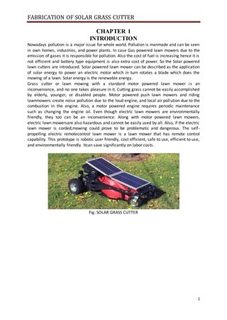
  • 1. FABRICATION OF SOLAR GRASS CUTTER 1 CHAPTER 1 INTRODUCTION Nowadays pollution is a major issue for whole world. Pollution is manmade and can be seen in own homes, industries, and power plants. In case Gas powered lawn mowers due to the emission of gases it is responsible for pollution. Also the cost of fuel is increasing hence it is not efficient and battery type equipment is also extra cost of power. So the Solar powered lawn cutters are introduced. Solar powered lawn mower can be described as the application of solar energy to power an electric motor which in turn rotates a blade which does the mowing of a lawn. Solar energy is the renewable energy. Grass cutter or lawn mowing with a standard motor powered lawn mower is an inconvenience, and no one takes pleasure in it. Cutting grass cannot be easily accomplished by elderly, younger, or disabled people. Motor powered push lawn mowers and riding lawnmowers create noise pollution due to the loud engine, and local air pollution due to the combustion in the engine. Also, a motor powered engine requires periodic maintenance such as changing the engine oil. Even though electric lawn mowers are environmentally friendly, they too can be an inconvenience. Along with motor powered lawn mowers, electric lawn mowersare also hazardous and cannot be easily used by all. Also, if the electric lawn mower is corded,mowing could prove to be problematic and dangerous. The self- propelling electric remotecontrol lawn mower is a lawn mower that has remote control capability. This prototype is robotic user friendly, cost efficient, safe to use, efficient to use, and environmentally friendly. Itcan save significantly on labor costs. Fig: SOLAR GRASS CUTTER
  • 2. FABRICATION OF SOLAR GRASS CUTTER 2 CHAPTER-2 LITERATURE SURVEY 2.1OBJECTIVE For the manufacturing of a solar grass cutter we referred various literature, papers etc. The review of previous method used given below: In this lawn mower uses an solar based energy source, which is easier to use, more advantageous comparing to other energy source especially for gas based source of power .But our lawn cutter is based on solar because this energy is a renewable energy source and it is easy to work. So we made solar powered lawnmower. In today's climate of growing energy needs and increasing environmental concern, alternatives to the use of non-renewable and polluting fossil fuels have to be investigated. One such alternative is solar energy. In this solar based lawn mower, the advantage of powering a lawn mower by solar rather than by gasoline is mainly ecological. We manufactured this lawn cutter because it is very easy method and many overcome produced from this type lawn cutter. The self-powered objective is to come up with a mower that is portable, durable, easy to operate and maintain. It also aims to design a self-powered mower of electrical source; a cordless electric lawn mower. The heart of the machine is a battery powered dc electric motor. It is also useful method for our lawn mower. It is similar to our lawn cutter using display and keypad. The present technology commonly used for trimming the grass is by using the manually handle device. In this project we have automated the machine for trimming the grass. The device consists of linear blade which is operated with the help of the motor the power supply for the motor is by using battery. The battery can be charge by using power supply and solar panel. 2.2 HISTORY The first lawn mower was invented by Edwin Budding in 1830 just outside Stroud, in Gloucestershire, England. Bedding’s mower was designed primarily to cut the grass on sports grounds and extensive gardens, as a superior alternative to the scythe, and was granted a British patent on August 31, 1830. Bedding’s first machine was 19 inches (480 mm) wide with a frame made of wrought iron. The mower was pushed from behind. Cast iron gear wheels transmitted power from the rear roller to the cutting cylinder, allowing the rear roller to drive the knives on the cutting cylinder; the ratio was 16:1. Another roller placed between the cutting cylinder and the main or land roller could be raised or lowered to alter the height of cut. The grass clippings were hurled forward into a tray-like box. It was soon realized, however, that an extra handle was needed in front to help pull the machine along. Overall, these machines were remarkably similar to modern mowers. Two of the earliest Budding machines sold went to Regent's Park Zoological Gardens in London and the Oxford Colleges. In an agreement between John Ferrabee and Edwin Budding dated May 18, 1830, Ferrabee paid the costs of enlarging the small blades, obtained letters of patent and acquired rights to manufacture, sell and license other manufacturers in the production of lawn mowers. Without patent, Budding and Ferrabee were shrewd enough to allow other companies to build copies of their mower under license,
  • 3. FABRICATION OF SOLAR GRASS CUTTER 3 the most successful of these being Ransoms of Ipswich, which began making mowers as early as 1832 Fig: An early cylinder reel mower His machine was the catalyst for the preparation of modern-style sporting ovals, playing fields (pitches), grass courts, etc. This led to the codification of modern rules for many sports, including for football, lawn bowls, lawn tennis and others From the late nineteenth century through the middle of the twentieth century, DC-to-AC power conversion was accomplished using rotary converters or motor-generator sets (M-G sets). In the early twentieth century, vacuum tubes and gas filled tubes began to be used as switches in inverter circuits. The most widely used type of tube was the thyratron. The origins of electromechanical inverters explain the source of the term inverter. Early AC- to-DC converters used an induction or synchronous AC motor direct-connected to a generator (dynamo) so that the generator's commentator reversed its connections at exactly the right moments to produce DC. A later development is the synchronous converter, in which the motor and generator windings are combined into one armature, with slip rings at one end and a commentator at the other and only one field frame. The result with either is AC-in, DC-out. With an M-G set, the DC can be considered to be separately generated from the AC; with a synchronous converter, in a certain sense it can be considered to be "mechanically rectified AC". Given the right auxiliary and control equipment, an M-G set or rotary converter can be "run backwards", converting DC to AC. Hence an inverter is an inverted converter. 2.3 FURTHER IMPROVEMENTS It took ten more years and further innovations to create a machine that could be drawn by animals, and sixty years before a steam-powered lawn mower was built. In the 1850s, Thomas Green & Son of Leeds introduced a mower called the SilensMessor (meaning silent cutter), which used a chain to transmit power from the rear roller to the cutting cylinder. These machines were lighter and quieter than the gear driven machines that preceded them, although they were slightly more expensive. The rise in popularity of lawn sports helped prompt the spread of the invention. Lawn mowers became a more efficient alternative to the scythe and domesticated grazing animals. Manufacture of lawn mowers took off in the 1860s. By 1862, Ferrabee's company was making eight models in various roller sizes. He manufactured over 5000 machines until production ceased in 1863. The first grass boxes were flat trays but took their present shape in the 1860s. James Sumner of Lancashire patented the first steam-powered lawn mower in 1893.
  • 4. FABRICATION OF SOLAR GRASS CUTTER 4 Fig: Commercial lawn mower Manufacture of lawn mowers took off in the 1860s. By 1862, Ferrabee's company was making eight models in various roller sizes. He manufactured over 5000 machines until production ceased in 1863. The first grass boxes were flat trays but took their present shape in the 1860s. James Sumner of Lancashire patented the first steam-powered lawn mower in 1893. The first United States patent for a reel lawn mower was granted to Amariah Hills on January 12, 1868. In 1870, Elwood McGuire of Richmond, Indiana designed a human-pushed lawn mower, which was very lightweight and a commercial success. John Burr patented an improved rotary-blade lawn mower in 1899, with the wheel placement altered for better performance. Amariah Hills went on to found the Archimedean Lawn Mower Co. in 1871. In the United States, gasoline powered lawn mowers were first manufactured in 1914 by Ideal Power Mower Co. of Lansing, Michigan, based on a patent by Ransom E. Olds. Ideal Power Mower also introduced the world's first self-propelled, riding lawn tractor in 1922, known as the "Triplex." The roller-drive lawn mower has changed very little since around 1930. Gang mowers, those with multiple sets of blades, were built in the United States in 1919 by the Worthington Mower Company. 2.4 ROTARY MOWERS Rotary mowers were not developed until engines were small enough and powerful enough to run the blades at sufficient speed. Many people experimented with rotary blade mowers in the late 1920s and early 1930s, and Power Specialties Ltd. introduced a gasoline-powered rotary mower. KutKwick replaced the saw blade of the "Pulp Saw" with a double-edged blade and a cutter deck, converting the "Pulp Saw" into the first ever out-front rotary mower. One company that produced rotary mowers commercially was the Australian Victa company, starting in 1952. Its mowers were lighter and easier to use than similar ones that had come before. The first Victa mowers were made at Mort lake, an inner suburb of Sydney, by local resident Mervyn Victor Richardson. He made his first model out of scrap in his garage and then moved to a shed behind St Mary's Church of England, where the first Victa mowers were manufactured, going on sale on 20 September 1952. The new company, Victa Mowers Pty Ltd, was incorporated on 13 February 1953.
  • 5. FABRICATION OF SOLAR GRASS CUTTER 5 Fig: Rotary mowers The venture was so successful that by 1958 the company moved to much larger premises in Parramatta Road, Concord, and then to Milperra, by which time the mower incorporated an engine, designed and manufactured by Victa, which was specially suitable for mowing, rather than employing a general-purpose engine.[12] Two Victa mowers, from 1958 and 1968 respectively, are held in the collection of the National Museum of Australia. The Victa mower is regarded as something of an Australian icon, appearing an masse, in simulated form, at the opening of the Sydney Olympic Games in 2000 2.5 SOLAR GRASS CUTTER The lawn mower or grass cutter is made up of a three motor, a battery, blades, and a link mechanism. The power and charging system comprises of an alternator which charges the battery while in operation. The D.C. motors forms the heart of the machine and provides the driving force for the blades and rear wheels. This is achieved by the combined effect of mechanical action of the cutting blades and the forward thrust of the mower. The system is powered by an electrical switch which completes the circuit comprising the in DC motor and the battery. The IR senor is finding the path to avoid the obstacles and machine damage. The shaft fitting mechanism with which the height of cut is altered. Solar power as an energy source will address a number of issues that standard internal combustion engine mowers do not. An electric grass cutter with a solar charger will be easier to use. There is no messy dangerous gasoline to deal with Most importantly it eliminates the emissions of an internal combustion mower. A lawn mower is a device which by means of one or more revolving blades issued to cutgrass or other plants to an even length. Lawnmowers employing a blade that rotates about a vertical axis are known as rotary mowers, while those employing a blade assembly that rotates about a horizontal axis are known as cylinder or reel mowers. Solar grass cutter are based on the use of small but powerful engine that provides enough torque to spin a very sharp horizontal blade that cuts the grass upon contact. The blade is located in the deck that prevents grass from flying all over the place when struck. In most cases, the motor is situated at the top of the deck, which is usually mounted on four wheels. There is also a bag connected to the deck that is used to collect cut grasses the opinion that lawnmowers must be designed to reduce pollutions generated than at present.
  • 6. FABRICATION OF SOLAR GRASS CUTTER 6 Solar grass cutter It uses the photovoltaic panel to generate the energy needed to power the mower. It is assumed that a lawnmower using solar as the energy source will address a number of issues that the standard internal combustion engine and electric motors lawn mowers do not. A lawnmower with solar energy will be easier to use, it eliminates down time by frequent trips to the gas station for fill-ups and danger associated with gasoline spillage. The dangerous emissions generated by the gasoline spillage and that of the internal combustion engine into the atmosphere are eliminated. The solar powered lawnmower will help to reduce air pollution as well as noise pollution produced by other types of lawnmowers. In addition, it will help to reduce the running cost of using and maintaining a lawnmower. The main components of the solar powered grass cutter  Solar panels  Brush less DC motor  Solar charger  Mechanism used  Circuit breaker  Blades  Batteries 2.6 BUMPER The physical bumper is made up of an inner square created by PVC pipe. The outside has PVC pipe with attached sheet metal that is attached to the inner square with PVC pipe loaded by a spring. There is a bolt through each spring connecting the outside and inside layer of the PVC pipe. The spring allows the bumper to compress when the mower has contact with an object. The bumper also has bolts through it that are there to activate the pushbuttons
  • 7. FABRICATION OF SOLAR GRASS CUTTER 7 2.7 MOTORS The Lawn Bot has a total of two motors. The blade mower came attached to the mower’s body frame. Both of its terminals are attached to a specified slot on the main terminal block. The other two mowers are used to move the wheels of the mower. They are both attached to the mower’s body frame with two U-bolts. The terminals for these two motors are attached to the motor driver’s terminals. Fig: Motor 2.8 CUTTING PATTERNS The lawn mower will have two types of cutting styles: spiral and random. The user will place therobot in the center of their lawn and let it cut. To achieve this cutting pattern both wheels must turn at two very different speeds with the outmost wheel moving the fastest. 5 Fig: Cutting patterns 2.9 TYPES OF LAWN MOWERS 2.9.1 CYLINDER LAWN MOWERS Cylinder lawn mowers consist of a cylinder and a number of horizontal blades that spiral around it. If adjusted to the correct height a cylinder mower will give the best cut of any lawn mower. They are however, best suited to flat lawns and can be difficult to use on bumpy or tall grass.
  • 8. FABRICATION OF SOLAR GRASS CUTTER 8 Fig: Cylinder Lawn Mowers 2.9.1.1 THE MAIN PARTS OF A CYLINDER REEL MOWER Blade reel cylinder consists of numerous (3 to 7) spiral blades that are attached to a rotating shaft. The blades rotate, creating a scissor-like cutting motion. Bed knife is the stationary cutting mechanism of a cylinder/reel mower. This is a fixed horizontal blade that is mounted to the frame of the mower. Body frame the main structural frame of the mower onto which the other parts of the mower are mounted. Wheels these help propel the mower in action. Generally, reel mowers have two wheels. Push handles the "power source" of a manually operated reel mower. This is a sturdy T- shape handle that is connected to the frame, wheels and blade chamber. Motor the power source of a reel mower that is powered by gasoline or electric Main parts of cylindrical mower 2.9.2 PETROL LAWN MOWERS These lawn mowers fall under the rotary type mowers. They are powered by internal combustion engines. Such engines can be either two-stroke or four-stroke cycle engines, running on gasoline or other liquid fuels. Internal combustion engines used with lawn mowers normally have only one cylinder. Power generally ranges from two to seven horsepower (1.5 to 5.25 kW). Petrol lawn mowers come in both the 2 stroke and 4 stroke cycle engines; 2 stroke lawn mowers are more powerful, less expensive, have a better power to weight ratio, and can be operated in any orientation. However, they are also louder, less fuel efficient, and do not last as long due to the high revolving engine. They also require the petrol to be mixed with oil prior to use in order to lubricate the engine. 4 stroke lawn mowers by comparison are not as powerful, but contain an oil sump (a separate oil chamber) and don't need the fuel to be pre-mixed. This saves the operator from mixing the fuel but it also means that the mower cannot be tipped. On one side as it will cause the oil to fall out of the sump into the fuel chamber. Petrol lawn mower
  • 9. FABRICATION OF SOLAR GRASS CUTTER 9 2.9.3 ELECTRIC LAWN MOWERS Rotary mowers powered by electric motors are increasingly popular. Usually, these mowers are moved by manual motive power the on-board engine or motor only spins the blades. These have the disadvantage of requiring a trailing power cord that limits its range and so these are only useful for relatively small lawns, close to a power socket. There is the obvious hazard with these machines of mowing over the power cable, which stops the mower and may put users at risk of electrocution. Electric Lawn Mowers 2.9.4 HOVER LAWN MOWERS Hover mowers are powered rotary push mowers that use a turbine above the spinning blades to drive air downwards, thereby creating an air cushion that lifts the mower off the ground like a hovercraft. The operator can then easily move the mower as it floats over the grass. Hover mowers can also be applied to very long grass and even light scrub, since their lightness permits most operators to lift the mower up and then let it sink slowly down while the blades progressively chop up the vegetation. Hover Lawn Mowers The lifting action is made even easier when the mower is swung around with the handle held against the operator's mid-body to provide leverage. The action of air lifting the mower off the grass makes it hover a few centimeters above the ground thus making it very easy to push around the garden and, providing that you are not interested in getting stripe. 2.9.5 RIDING LAWN MOWERS A popular alternative for larger lawns is the ride-on mower. The operator is provided with a seat and controls on the mower and literally 'rides' on the machine. Most use the horizontal rotating blade system, though usually with multiple blades. A common form of ride-on mower is the lawn tractor. These are usually designed to resemble a small agricultural tractor, with the cutting deck mounted amidships between the front and rear axles. An alternative layout for a ride-on is that with the mowing decks in front of the machine, often called zero-turn mowers because
  • 10. FABRICATION OF SOLAR GRASS CUTTER 10 of their maneuverability. Mowing decks on ride on mowers are rotary and have two or three cutting blades Fig: Riding Lawn Mowers 2.9.6 ROBOTIC LAWN MOWERS A typical robotic lawn mower requires the user to set up a border wire around the lawn that defines the area to be mowed. The robot uses this wire to trim and in some cases to locate a recharging dock. Robotic mowers are capable of maintaining up to 5 acres of grass. Electricity usage varies from about 100 watts for 1/2 acre to 500 watts to maintain 5 acres. Robotic lawnmowers are increasingly sophisticated, are self-docking and contain rain sensors nearly eliminating human interaction for mowing grass. Some models will adapt their programming by detecting the speed in which grass grows as needed to maintain a perfect cut lawn. Fig: Robotic lawn mowers 2.10 PLASTIC WHEELS The plastic wheels will be connected to the DC motors. As soon as they create the torque, these wheels will help the move Fig: Plastic wheels 2.11 THE FRAME OF SOLAR GRASS CUTTER A mild steel plate was used in the construction of the frame due to its strength, workability, availability and cost effectiveness. The frame provides support for the electric motor,
  • 11. FABRICATION OF SOLAR GRASS CUTTER 11 battery as well as the handle frame. The diameter of the deck is 25cm and height 40cm deck is also made of four hand lever adjusters which are used to raise and lower the deck to the desired height of cut. Each is made of flat metal with five spin hooks to aid the operation. They transmit the load of 15kg to the wheel equally and length of each is 30 diameters. Fig: THE FRAME OF SOLAR GRASS CUTTER
  • 12. FABRICATION OF SOLAR GRASS CUTTER 12 CHAMPTER -3 EXPERIMENTATION 3.1 SOLAR ENERGY Here the solar energy are two types one is sensible heat storage and another one is latent heat storage here we are using sensible type by using this type we can produce 12v and 10w we can store this energy into battery within 5 to 10 hours by using those energy we can run the grass cutter. Fig: SOLAR ENERGY WORKING 3.2 SOLAR PANEL A solar panel is a set of solar photovoltaic modules electrically connected and mounted on a supporting structure. A photovoltaic module is a packaged, connected assembly of solar cells. The solar panel can be used as a component of a larger photovoltaic system to generate and supply electricity in commercial and residential applications. Each module is rated by its DC output power under standard test conditions (STC), and typically ranges from 100 to 320 watts. The efficiency of a module determines the area of a module given the same rated output - an 8% efficient 230 watt module will have twice the area of a 16% efficient 230 watt module. A single solar module can produce only a limited amount of power; most installations contain multiple modules. A photovoltaic system typically includes a panel or an array of solar modules, an inverter, and sometimes a battery and/or solar tracker and interconnection wiring. 3.3 PHOTOVOLTAIC PRINCIPLES The photo- voltaic effect can be observed in nature in a variety of materials that have shown that the best performance in sunlight is the semiconductors as stated above. When photons from the sun are absorbed in a semiconductor, that create free electrons with higher energies than the created there must be an electric field to induce these higher energy electrons to flow out of the semi-conductor to do useful work. A junction of materials, which have different electrical properties, provides the electric field in most solar cells for the photon interaction in a semiconductor. Solar photovoltaic cells are essentially semi-conductors, which have electrical transmission properties like metal or salt water and insulators like rubber. Panels are constructed with sheets of doped silicon, primary element in beach sand with impurities added like phosphorus that allows electrons to flow. When the protons from the solar energy hit a photovoltaic cell, a flow of electrons starts which can be drawn off by a pair of wires, thereby creating direct current. A number of solar cells electrically connected to each other and mounted in a support structure or frame is called a photovoltaic module. Modules are designed to supply electricity at a certain voltage. The current produced is directly dependent on how much light strikes the module.
  • 13. FABRICATION OF SOLAR GRASS CUTTER 13 A solar cell consists of Semi-conductor in which electron hole pairs are created by the absorption of incident solar radiation. Region containing a drift field for charge separation. Charge collecting front and back electrodes. 3.4 PHOTOVOLTAIC EFFECT The photo-voltaic effect can be described easily for p-n junction in a semi-conductor. In an intrinsic semi-conductor such as silicon, each one of the four valence electrons of the material atom is tied in a chemical bond, and there are no free electrons at absolute zero. If a piece of such a material is doped on one side by a five valance electron material, such as arsenic or phosphorus, there will be an excess of electrons in that side, becoming an n-type semi-conductor. The excess electrons will be practically free to move in the semi-conductor lattice. When a three valance electron material, such as boron dopes the other side of the same piece, there will be deficiency of electrons leading to a p-type semi-conductor. This deficiency is expressed in terms of excess of holes free to move in the lattice. Such a piece of semi- conductor with one side of the p-type and the other, of the n-type is called p-n junction. In this junction after the protons are absorbed, the free electrons of the n-side will tends to flow to the p-side, and the holes of the p-side will tend to flow to the n-region to compensate for their respective deficiencies. This diffusion will create an electric field from the n-region to the p-region. This field will increase until it reaches equilibrium for voltage, the sum of the diffusion potentials for holes and electrons. If electrical contacts the connected through an external electrical conductor, the free electrons will flow from the n-type material through the conductor to the p-type material. Here the free electrons will enter the holes and become bound electrons thus both free electrons and holes will be removed. The flow of electrons through the external conductor constitutes an electric current, which will continue as long as move free electrons and holes are being formed by the solar radiation. This is the basis of photo-voltaic conversion that is the conversion of solar energy into electrical energy. The combination of n-type and p-type semiconductors thus constitutes a photo-voltaic cell or solar cell. All such cells some rate direct current that can be converted into alternating current it desired. The photo-voltaic effect can be observed in almost any junction of material that have different electrical characteristics, but the best performance to date has been from cells using semiconductor material especially all of the solar cells used for both space and terrestrial applications have been made of the semiconductor silicon. 3.5 THE RACK FOR SOLAR PANEL This is the main solar panel safety device. It provides tight and safe holding reducing the risk of a new panel. The design was done within our specific panel dimensions, modifications can be done to accommodate other panel sizes. Some factors that were taken into account included  The base stands of the holder (firm to enable steady positioning)  The height from the ground, (high to reduce obstacle interference)  The weight and strength of the materials used (for durability and mobility)  The corrosion resistance of the materials. (In corrosive environments).  Angular adjustment (for angular adjustments for maximum isolation )
  • 14. FABRICATION OF SOLAR GRASS CUTTER 14 We need an angle line steel bar 40mm in width from which we cut 4 pieces, two of 750mm length and the other two of 540mm length. The 4 pieces are welded together to form a rectangular frame of dimensions 750mm by 540mm.The remaining angle plate is used to fabricate the stand onto which the frame is mounted to. Fig: The rack for solar panel 3.6 APPLICATIONS OF SOLAR TECHNOLOGY Solar energy refers primarily to the use of solar radiation for practical ends. However, all renewable energies, other than geothermal and tidal, derive their energy from the sun. Solar technologies are broadly characterized as either passive or active depending on the way they capture, convert and distribute sunlight. Active solar techniques use photovoltaic panels, pumps, and fans to convert sunlight into useful outputs. Passive solar techniques include selecting materials with favorable thermal properties, designing spaces that naturally circulate air, and referencing the position of a building to the Sun. Active solar technologies increase the supply of energy. 3.7 THE ENVIRONMENT USE Solar energy is a renewable resource. A renewable resource is a resource that is able to be replaced or replenished, either by the earth's natural processes or by human action. Solar energy is available at varying proportions almost everywhere on earth. It cannot be depleted unlike the fossil fuel based energy resources. Solar energy is a “clean” energy resource. It does not involve the emission of Green House Gases (GHGs) that are believed to be responsible for the worsening global warming of our planet, Earth. 3.8 DC MOTORS A DC motor is a mechanically commutated electric motor powered from direct current (DC). The stator is stationary in space by definition and therefore so is its current. The current in the rotor is switched by the commentator to also be stationary in space. This is how the relative angle between the stator and rotor magnetic flux is maintained near 90 degrees, which generates the maximum torque. DC motors have a rotating armature winding (winding in which a voltage is induced) but non-rotating armature magnetic field and a static field winding (winding that produce the main magnetic flux) or permanent magnet. Different connections of the field and armature winding provide different inherent speed/torque regulation characteristics. The speed of a DC motor can be controlled by changing the voltage applied to the armature or by changing the field current.
  • 15. FABRICATION OF SOLAR GRASS CUTTER 15 The introduction of variable resistance in the armature circuit or field circuit allowed speed control. Modern DC motors are often controlled by power electronics systems called DC drives. Fig: DC Motors The introduction of DC motors to run machinery eliminated the need for local steam or internal combustion engines, and line shaft drive systems. DC motors can operate directly from rechargeable batteries, providing the motive power for the first electric vehicles. Today DC motors are still found in applications as small as toys and disk drives, or in large sizes to operate steel rolling mills and paper machines. DC motors are configured in many types and sizes, including brush less, servo, and gear motor types. A motor consists of a rotor and a permanent magnetic field stator. The magnetic field is maintained using either permanent magnets or electromagnetic windings. DC motors are most commonly used in variable speed and torque. Motion and controls cover a wide range of components that in some way are used to generate and/or control motion. Areas within this category include bearings and bushings, clutches and brakes, controls and drives, drive components, encoders and resolves, Integrated motion control, limit switches, linear actuators, linear and rotary motion components, linear position sensing, motors (both AC and DC motors), orientation position sensing, pneumatics and pneumatic components, positioning stages, slides and guides, power transmission (mechanical), seals, slip rings, solenoids, springs. Motors are the devices that provide the actual speed and torque in a drive system. This family includes AC motor types (single and multiphase motors, universal, servo motors, induction, synchronous, and gear motor) and DC motors (brush less, servo motor, and gear motor) as well as linear, stepper and air motors, and motor contactors and starters. In any electric motor, operation is based on simple electromagnetism. A current-carrying conductor generates a magnetic field; when this is then placed in an external magnetic field, it will experience a force proportional to the current in the conductor, and to the strength of the external magnetic field. As you are well aware of from playing with magnets as a kid, opposite (North and South) polarities attract, while like polarities (North and North, South and South) repel. The internal configuration of a DC motor is designed to harness the magnetic interaction between a current-carrying conductor and an external magnetic field to generate rotational motion. Let's start by looking at a simple 2-pole DC electric motor (here red represents a magnet or winding with a "North" polarization, while green represents a magnet or winding with a "South" polarization). Every DC motor has six basic parts axle, rotor (a.k.a., armature), stator, commentator, field magnet(s), and brushes. In most common DC motors (and all that Beamers will see), the external magnetic field is produced by high-strength permanent magnets.
  • 16. FABRICATION OF SOLAR GRASS CUTTER 16 The stator is the stationary part of the motor this includes the motor casing, as well as two or more permanent magnet pole pieces. The rotor rotates with respect to the stator. The rotor consists of windings (generally on a core), the windings being electrically connected to the commentator. The above diagram shows a common motor layout with the rotor inside the stator (field) magnets. The geometry of the brushes, commentator contacts, and rotor windings are such that when power is applied, the polarities of the energized winding and the stator magnet(s) are misaligned, and the rotor will rotate until it is almost aligned with the stator's field magnets. As the rotor reaches alignment, the brushes moves to the next commutate contacts, and energize the next winding. Given our example two-pole motor, the rotation reverses the direction of current through the rotor winding, leading to a "flip" of the rotor's magnetic field, and driving it to continue rotating. In real life, though, DC motors will always have more than two poles (three is a very common number). In particular, this avoids "dead spots" in the commentator. You can imagine how with our example two-pole motor, if the rotor is exactly at the middle of its rotation (perfectly aligned with the field magnets), it will get "stuck" there. Meanwhile, with a two-pole motor. There is a moment where the commentator shorts out the power supply (i.e., both brushes touch both commentator contacts simultaneously). This would be bad for the power supply, waste energy, and damage motor components as well. Yet another disadvantage of such a simple motor is that it would exhibit a high amount of torque” ripple" (the amount of torque it could produce is cyclic with the position of the rotor). So since most small DC motors are of a three-pole design, let's tinker with the workings of one via an interactive animation (JavaScript required): You'll notice a few things from this -- namely, one pole is fully energized at a time (but two others are "partially" energized). As each brush transitions from one commentator contact to the next, one coil's field will rapidly collapse, as the next coil's field will rapidly charge up (this occurs within a few microsecond). We'll see more about the effects of this later, but in the meantime you can see that this is a direct result of the coil windings' series wiring: There's probably no better way to see how an average dc motor is put together, than by just opening one up. Unfortunately this is tedious work, as well as requiring the destruction of a perfectly good motor. This is a basic 3-pole decimator, with 2 brushes and three commentator contacts. An electrostatic motor is based on the attraction and repulsion of electric charge. Usually, electrostatic motors are the dual of conventional coil-based motors. They typically require a high voltage power supply, although very small motors employ lower voltages. Conventional electric motors instead employ magnetic attraction and repulsion, and require high current at low voltages. In the 1750s, the first electrostatic motors were developed by Benjamin Franklin and Andrew Gordon. Today the electrostatic motor finds frequent use in micro-electro- mechanical systems (MEMS) Where their drive voltages are below 100 volts, and where moving, charged plates are far easier to fabricate than coils and iron cores. Also, the molecular machinery which runs living cells is often based on linear and rotary electrostatic motors
  • 17. FABRICATION OF SOLAR GRASS CUTTER 17 A piezoelectric motor or pies motor is a type of electric motor based upon the change in shape of a piezoelectric material when an electric field is applied. Piezoelectric motors make use of the converse piezoelectric effect whereby the material produces acoustic or ultrasonic vibrations in order to produce a linear or rotary motion. In one mechanism, the elongation in a single plane is used to make series stretches and position. An electrically powered spacecraft propulsion system uses electric motor technology to propel spacecraft in outer space, most systems being based on electrically powering propellant to high speed, with some systems being based on electrodynamics tethers principles of propulsion to the magnetosphere. 3.9 MOUNTING THE MOTOR Hear two motors are connected to wheels which is used to move the cutter it get supply from battery and another motor is fixed on center and it is used to cut the grass this motor can adjustable with the help of nut.These motors are the fixed to mild steel bed. Here we are using high torque motors. 3.10BLADES A blade is that portion of a tool, weapon, or machine with an edge that is designed to cut and/or puncture, stab, slash, chop, slice, thrust, or scrape surfaces or materials. The blade is seldom sharp enough to give a neat cutting. The blade simply tears the grass resulting in brown tips. However, the horizontal blades are easy to remove and sharpen or replace. Existing engine trimmers suffer from high initial cost, high levels of engine noise, high fuel consumption rates and high operator’s fatigue in long-run. Mower blades are the cutting components of lawn mowers. They are usually made of sturdy metals as they must be able to withstand high-speed contact with a variety of objects in addition to grass. The materials used (as well as size, thickness, and design of the blades) vary by manufacturer. A blade may be made from a flaking stone, such as flint, metal (usually steel), ceramic, or other material. Here we used two blades i.e. fixed blade and sliding blade. Fig: Grass cutting blade The first known lawn mower sported a cylinder cutting gear made of iron. It was used to mow sporting grounds and wide-ranging gardens. As manufacturers changed the design and structure of mowers, the cutting mechanism also developed and evolved into several varieties, including cylinder/reel blades, deck blades, mulching blades, and lifting blades
  • 18. FABRICATION OF SOLAR GRASS CUTTER 18 3.11 FIXED BLADE The blade which has no motion is called Fixed blade. This fixed blade is welded to the frame .And this is placed below the sliding blade. Fig: Fixed blade 3.12 SLIDING BLADE This blade slide over the moving blade .This blade is connecting to wheel and this is connected to DC motor. Fig: Sliding blade 3.13 MOUNTING THE BLADE This is the most important part and when designing for this, safety as a major factor was put into consideration as the blade when in operation can be a safety hazard. Also the weight of the blade and how to mount it on the motor shaft is also a key consideration. Moreover the sharpness of the blade is another important aspect and this will depend on the power and the RPM of the motor used. Fig: Mounting the Blade Unfortunately, when removing the old blade from the old mower I was unable to salvage the piece that attached the engine shaft to the mower blade. This meant that it was necessary to fabricate my own blade mount. I found a piece of metal rod about 3/4" in diameter in the scrap pile in the HSU metals lab. I bored a hole into the rod at about 3/8" in diameter (the motor shaft diameter). This would allow the rod to slide over the motor shaft. Next the rod needed a key way milled to allow a key to be inserted.
  • 19. FABRICATION OF SOLAR GRASS CUTTER 19 The key connects the rod to the shaft and keeps the rod from slipping while the shaft is rotating. Then I cut the rod to length and welded it to an 1/8" thick metal plate that the mower blade will be bolted to. After the blade mount was finished being fabricated I inserted it on to the shaft. Then to make sure the mount was supported vertically I drilled a small hole completely through the mount and shaft. This allowed me to insert a bolt as an added safety measure. When the blade mount was securely mounted I bolted the mower blade to it using two 3/8" nuts and bolts with washers. All in all the fabrication of the blade mount went well. 3.14 THE MOWER BLADE The blade is to be designed in such a way with high accuracy because it is essentially the cutting tool of the mower; a picture of an ordinary gas lawn mower blade. Fig: Mower Blade Various critical factors governed by the motor speed were considered in choosing the blade material, they include: The weight of blade material The strength of the blade material The blade size in length The blade size in thickness Safety to the user Apart from all these factors combined, the need for an easily sharpened material was also considered in the case of maintenance. So as to achieve maximum efficiency from the motor hence the whole lawn mower, the blade must be absolutely sharp. Sharpening is done quite often by grinding. The blade has to be mounted firmly to the motor shaft so as to guarantee maximum safety and regular rotation. A balance on the blade has to be achieved such that there is even rotation of blade i.e. a split taper bushing and a pulley is used to mount and align the blade onto the motor shaft preventing vibration and excessive wear on the motor shaft and bearings. Split bushings have an advantage in the way they hold the pulley very firmly to the shaft and can accommodate a lot of vibration. The bushings also have a slot to prevent rotational slippage. The pulley helps in fastening the taper bushing to the shaft. After fabricating the blade we bolt it onto the bushing collar using two bolts of the same thread form to those of the bushing. Now the blade is firmly mounted on our mower. The number of blades that spiral around the cylinder determines the quality of the finish, the more blades, the better and the cut. Cylinder mowers can also be fixed with a roller which flattens the grass giving a smooth finish. A cylinder mower with a rear roller will give the best striped effect. Some cylinder mowers are entirely hand driven whereas others may have the blades driven by an engine. Self-propelled cylinder mowers use an engine to propel themselves forward as well as to turn the blades. This can save the operator a lot of energy as little effort is required to move the mower around the lawn.
  • 20. FABRICATION OF SOLAR GRASS CUTTER 20 3.15 TYPES OF GRASS CUTTING BLADES 3.15.1 REEL OR CYLINDER BLADES Used in reel or cylinder mowers, cylinder blades are composed of three to seven helical blades welded in a horizontally rotating cylindrical reel, creating a scissor-like cutting action. Unlike other types of mower blades, reel/cylinder blades cannot be replaced. Therefore, a broken blade requires replacement of the entire mower. For dull or rusty blades, cleaning and sharpening kits are available. Fig: Reel or Cylinder blade 3.15.2 DECK BLADES Also known as the standard or straight mower blade, this is the most commonly used blade on rotary mowers. The blade of a rotary mower is usually mounted directly to the crankshaft of its engine, but it can be propelled by a hydraulic motor or a belt pulley system Fig: Deck blades 3.15.3 MULCHING BLADES A mulching blade, also known as an all-purpose blade, features a curved surface which allows it to work in three ways: lifting, mowing, and mulching. First, the blade pulls the grass up and cuts it. Then, clippings are sucked inside the deck and are chopped into tinier pieces. Finally, the blade’s innermost curve produces air pressure to blow the small clippings out, where they are used to feed the soil.
  • 21. FABRICATION OF SOLAR GRASS CUTTER 21 Fig: Mulching Blades 3.15.4 LIFTING BLADES The lifting blade features a slightly curved surface which creates a vertical upward airflow that lifts the grass up and is assumed to provide a cleaner result than the other types of blades. Lifting blades 3.15.5 LOW-LIFT BLADE Low suction power recommended for mowing terrain with sandy soil. 3.15.6 MEDIUM-LIFT BLADE Medium suction power; uses less horsepower than high-lift blades. 3.15.7 HIGH-LIFT BLADE Provides the greatest suction power among the three lifting blades, but also requires the most horsepower. This is the best blade for cutting tall, compact grass.
  • 22. FABRICATION OF SOLAR GRASS CUTTER 22 CHAPTER -4 DESIGINED MODEL 4.1 WORKING PRINCIPLE OF SOLAR POWERED GRASS CUTTER The working principle of solar grass cutter is it has panels mounted in a particular arrangement at an in such a way that it can receive solar radiation with high intensity easily from the sun. These solar panels convert solar energy into electrical energy. This electrical energy is stored in batteries by using a solar charger. The main function of the solar charger is to increase the current from the panels while batteries are charging, it also disconnects the solar panels from the batteries when they are fully charged and also connects to the panels when the charging in batteries is low. The motor is connected to the batteries through connecting wires .Between these two mechanical circuit breaker switch is provided. It starts and stops the working of the motor. From this motor, the power transmits to the mechanism and this makes the blade to slide on the fixed blade and this makes to cut the grass. Fig: Solar Powered Grass Cutter The designed solar powered lawnmower comprises of direct current (D.C) motor, a rechargeable battery, solar panel, a stainless steel blade and control switch. Mowing is achieved by the D.C motor which provides the required torque needed to drive the stainless steel blade which is directly coupled to the shaft of the D.C motor. The solar powered lawnmower is operated by the switch on the board which closes the circuit and allows the flow of current to the motor which in turn drive the blade used for mowing. The battery recharges through the solar charging controller. Performance evaluation of the developed machine was carried out with different types of grasses. 4.2 OPERATION PRINCIPLE OF DC MOTOR Electrical energy of the battery is converted to mechanical energy through a set of blades designed to achieve cutting operation. The electric circuit ensures power transfer from the battery to run the D.C. motor, whilst the solar panel power to continuously recharge the battery while in operation. The cutting blades tap power from the D.C. motor. When the power switch is on, the electrical energy from the battery powers the motor which in turn actuates the blades. The solar panel generates current to recharge the battery,
  • 23. FABRICATION OF SOLAR GRASS CUTTER 23 thereby compensating for the battery discharge. The rotating blades continuously cut the grass as the mower is propelled forward and the cut grass. Height of cut is adjusted by means of the link mechanism via the lift rod Fig: DC Motor Blade. 4.3BRUSH A brushed DC electric motor generating torque from DC power supply by using internal mechanical commutation, space stationary permanent magnets form the stator field. Advantages of a brushed DC motor include low initial cost, high reliability, and simple control of motor speed. Disadvantages are high maintenance and low life-span for high intensity uses. Maintenance involves regularly replacing the carbon brushes and springs which carry the electric current, as well as cleaning or replacing the commentator. These components are necessary for transferring electrical power from outside the motor to the spinning wire windings of the rotor inside the motor. Brushes consist of conductors. Torque is produced by the principle of Lorentz force, which states that any current-carrying conductor placed within an external magnetic field experiences a force known as Lorentz force. The actual (Lorentz) force ( and also torque since torque is F x l where l is rotor radius) is a function for rotor angle and so the green arrow/vector actually changes length/magnitude with angle known as torque ripple) Since this is a single phase two pole motor the commentator consists of a split ring. So that the current reverses each half turn. .The brushed electric motor generates torque directly from DC power supplied to the motor by using internal commutation, stationary magnets and rotating electrical magnets. Like all electric motors or generators, torque is produced by the principle of Lorentz force, which states that any current-carrying conductor placed within an external magnetic field experiences a torque or force known as Lorentz force. Advantages of a brushed DC motor include low initial cost, high reliability, and simple control of motor speed. Disadvantages are high maintenance and low life-span for high intensity uses . Maintenance involves regularly replacing the brushes and springs which carry the electric current, as well as cleaning or replacing the commentator these components are necessary for transferring electrical power from outside the motor to the spinning wire windings of the rotor inside the motor. Brushes are made of conductors. 4.4 UNCOMMITTED Other types of DC motors require no commutation. 4.4.1 HOMOPOLAR MOTOR A homopolar motor has a magnetic field along the axis of rotation and an electric current that at some point is not parallel to the magnetic field. The name homopolar refers to the absence of polarity change. Homopolar motors necessarily have a single-turn coil, which
  • 24. FABRICATION OF SOLAR GRASS CUTTER 24 limits them to very low voltages. This has restricted the practical application of this type of motor. Fig: Homopolar Motor BALL BEARING MOTOR A ball bearing motor is an unusual electric motor that consists of two ball bearing- type bearings, with the inner races mounted on a common conductive shaft, and the outer races connected to a high current, low voltage power supply. An alternative construction fits the outer races inside a metal tube, while the inner races are mounted on a shaft with a non-conductive section (e.g. two sleeves on an insulating rod). This method has the advantage that the tube will act as a flywheel. The direction of rotation is determined by the initial spin which is usually required to get it going. Ball Bearing Motor 4.5 THEORY OF DC MOTOR SPEED CONTROL ` The speed controller works by varying the average voltage sent to the motor. It could do this by simply adjusting the voltage sent to the motor, but this is quite inefficient to do. A better way is to switch the motor's supply on and off very quickly. If the switching is fast enough, the motor doesn't notice it, it only notices the average effect. When we watch a film in the cinema, or the television, what you are actually seeing is a series of fixed pictures, which change rapidly enough that your eyes just see the average effect - movement. Your brain fills in the gaps to give an average effect. Now imagine a light bulb with a switch. When you close the switch, the bulb goes on and is at full brightness, say 100 Watts. When you open the switch it goes off (0 Watts). Now if you close the switch for a fraction of a second, and then open it for the same amount of time, the filament won't have time to cool down and heat up, and you will just get an average glow of 50 Watts. This is how lamp dimmers work, and the same principle is used by speed controllers to drive a motor. When the switch is closed, the motor sees 12 Volts, and when it is open it sees 0 Volts. If the switch is open for the same amount of time as it is closed, the motor will see an average of 6 Volts, and will run more slowly accordingly. The time that it takes a motor to speed up and slow down under switching conditions is dependent on the inertia of the rotor (basically how heavy it is), and how much friction and load torque there is.
  • 25. FABRICATION OF SOLAR GRASS CUTTER 25 4.6 SOLAR CHARGER The power charge regulator is also known as charge controller, voltage regulator, charge- discharge controller or charge-discharge and load controller. The regulator sits between the array of panels, the batteries, and the equipment or loads. The charging station is like the refill station for our battery which is used as a source of energy to drive the motor. This is done initially before using the battery for the first time and subsequently thereafter each mowing session depleting its charge. Importantly, since the solar panel and charge controller are of specified ratings, most of our design went to the solar panel rack holder . Solar Chargers Solar chargers should never be connected in parallel. In order to protect the battery from gasification, the switch opens the charging circuit when the voltage in the battery reaches its high voltage disconnects (HVD) or cut-off set point. The low voltage disconnects (LVD) prevents the battery from over discharging by disconnecting the load. The most modern regulators are also able to automatically disconnect the panels during the night to avoid discharging of the battery. They can also periodically overcharge the battery to improve their life, and they may use a mechanism known as pulse width modulation (PWM). Solar charger has three light indicators. The first light blinks when the batteries are charging by using solar energy. The second light glows when the charging in the batteries is very low. The third light glows when the batteries are fully charged and an extra load (charging) is applied on the batteries. By monitoring the voltage of battery, the regulator prevents overcharging or over discharging. Regulators used in solar applications should be connected in series: they disconnect the array of panels from the battery to avoid overcharging, and they disconnect the battery from the load to avoid over discharging. The connection and disconnection is done by means of switches which can be of two types: electromechanical (relays) or solid state (bipolar transistor). 4.7 THE CHARGE CONTROLLER The charge controller or control panel as it is commonly known has two primary functions. First, it provides a central point for connecting the load, the module and the battery. Secondly, it manages the system so that the harvested electricity is effectively used, and so that components are protected from damage due to changing voltage levels. The charge controller at the very least should act as a junction box. Here, the battery, load and solar module are fastened together by means of connector strips. Fuses are incorporated to protect the equipment from damage by short circuits. Charge controllers contain a blocking diode.
  • 26. FABRICATION OF SOLAR GRASS CUTTER 26 This blocking diode prevents current from flowing from the batteries to the solar cell module when the battery voltage is higher than the module voltage. This prevents energy losses in the system. 4.8 BATTERY Solar cell modules produce electricity only when the sun is shining. They do not store energy, therefore to ensure flow of electricity when the sun is not shinning, it isnecessary to store some of the energy produced. The most obvious solution is to use batteries, which chemically store electric energy. Batteries are groups of electro-chemical cells (devices that convert chemical energy to electrical energy connected in series. Battery cells are composed of two electrodes immersed in electrolyte solution which produce an electric current when a circuit is formed between them. The current is caused by reversible chemical reactions between the electrodes and the electrolyte within the cell.Batteries that are re-chargeable are called secondary or accumulator batteries. As the battery is being charged, electric energy is stored as chemical energy in the cells. When being discharged, the stored chemical energy is being removed from the battery and converted to electrical energy. Battery The batteries are used as a storage device for solar energy which can be further converted into electrical energy. The only exceptions are isolated sunshine load such as irrigation pumps or drinking water supplies for storage, for small units with output less than one kilowatt. Batteries seem to be the only technically and economically available storage means. Since both the photo- voltaic system and batteries are high in capital costs, it is necessary that the overall system be optimized with respect to available energy and local demand pattern. 4.9 BATTERY MOUNTING Once the motor was mounted needed to find a place for the battery to sit. As mentioned in the mounting the motor section, the base of the motor was facing the rear of the mower and would provide a solid mounting surface for the battery mount. To get the proper weight distribution I wanted to mount the battery as close as could to the back wheels. This would allow the handle bars to serve as a lever and allow the mower to easily pivot when on its back wheels. Using a piece of stainless steel purchased from a local scrap yard fabricated the battery mount. It started by placing the battery in the center of the square piece of stainless steel. Then marked the outline of the battery on to the steel. Next cut the corners to allow the sides that extend beyond the battery to be folded up. After folding up all four sides welded them together for support. The battery fits tightly into the mount so no excess strapping is needed.
  • 27. FABRICATION OF SOLAR GRASS CUTTER 27 CHAPTER-5 REPORT 5.1 MECHANICAL ARRANGEMENTS In the first phase we just considered only about the mechanical arrangements, which is responsible for rotating the dynamo. For this the team members divided the work into two divisions. The mechanical arrangement consisting of External framework Solar frame Shaft with free-wheeling bearing Wheels with DC motor Blades Battery 5.2 EXTERNAL IRON FRAME WORK The external frame work is having 20/15 inches .There are four pairs of cylindrical hollow pipes are welded as pillars, which will give the support for the surface of the platform At the bottom of the platform we have attached a lever .Hence when a pressure is applied on the surface of the platform the platform compresses softly with the help of springs which is attached between the platform and the hollow cylindrical iron pipes and the suspension for the platform will be given by the spring .the spring will compress for the average weight of 55 to 70 kg. The spring’s compression is tested for average weight using the spring balance 5.3 SOLAR FRAME The solar frame having the iron cylindrical hollow pipes are welded in square shape which is used to carry the solar panel. The solar panel is 12watts which is connected to the battery. 5.4 SHAFT WITH FREE-WHEEL BEARING The shaft is clamped between the iron frame work and the freewheeling type bearings are attached on the shaft. The free-wheel bearing rotates only in one direction which resembles the cycle. Hence the pressure applied is perfectly delivered to the shaft. In this Shaft we have connected a spring which gets straightened when the load is applied and it gets to compress when it is removed hence it pull the shaft which will give additional rotation for the pulley. 5.5 WHEELS WITH DC MOTOR The wheels are connected to the dc motor which is used to cut the grass very fast and smooth. Due to this wheel with dc motor it moves fast. This dc motors are arranged both the side of solar grass cutter .Each wheel is attached to a dc motor. This dc motors are with 100rpm with hydraulic gearing system. Wheel radius is 1.5 inches. 5.6 BLADES The blades are mounted according to the need. After the blade mount was finished being fabricated I inserted it on to the shaft. Then to make sure the mount was supported vertically drilled a small hole completely through the mount and shaft. This allowed me to insert a bolt as an added safety measure. It is easy to cut the grass and the moving of blades will be freely. This blade rotates with the help of a dc motor which is connected with this blade. Due this dc motor the blades rotates very fast which uses to cut the grass. This dc motors are 1000
  • 28. FABRICATION OF SOLAR GRASS CUTTER 28 rpm with hydraulic gear motors 12 watts. There are two blades one in arranged front of the solar grass cutter and another blade is arranged at the back side of the grass cutter. 5.7 BATTERY The solar energy was saved in the battery.Batteries that are re-chargeable are called secondary or accumulator batteries. As the battery is being charged, electric energy is stored as chemical energy in the cells. When being discharged, the stored chemical energy is being removed from the battery and converted to electrical energy. The battery is 12watts
  • 29. FABRICATION OF SOLAR GRASS CUTTER 29 CHAPTER-6 CONCLUSION The project ismore suitable for common man as it is having much more advantages i.e, no fuel cost, no pollution, and no fuel residue. Less wear and tear because of less number of moving components and this can be operated by using solar energy. This will give much more physical exercise to the people and can be easily handled. This system is having facility of charging the batteries while the solar powered grass cutter is in motion. So it is much more suitable for grass cutting also. The same thing can be operated in night time also, as there is a facility to charge these batteries in day light. The frame which we use doesn’t have height adjustment. This can be overcome by keeping wheels arrangement near the blades. The project which we have done surely reaches the average families because the grass can be trimmed with minimum cost and with minimum time. Finally the project may give an inspiration to the people who can obtain better res