SMTAS04USB mini – Evaluation board for SMT172
•
0 likes•42 views

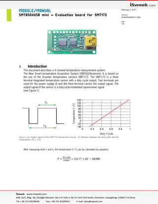
This document describes a 4 channel temperature measurement system: The New Smart Temperature Acquisition System (SMTAS04usbmini). It is based on the use of the Smartec temperature sensors SMT172. The SMT172 is a three terminal integrated temperature sensor with a duty cycle output. Two terminals are used for the power supply of and the third terminal carries the output signal. The output signal of the sensor is a duty-cycle-modulated square-wave signal (see Figure 1).

Recommended
Recommended
More Related Content
Similar to SMTAS04USB mini – Evaluation board for SMT172
Similar to SMTAS04USB mini – Evaluation board for SMT172 (20)
Recently uploaded
Recently uploaded (20)
SMTAS04USB mini – Evaluation board for SMT172
- 1. MODULE/MANUAL SMTAS04USB mini – Evaluation board for SMT172 last update February 2, 2017 reference smtas04usbmini n.doc page 1/4 1 Introduction This document describes a 4 channel temperature measurement system: The New Smart temperature Acquisition System (SMTAS04usbmini). It is based on the use of the Smartec temperature sensors SMT172. The SMT172 is a three terminal integrated temperature sensor with a duty cycle output. Two terminals are used for the power supply of and the third terminal carries the output signal. The output signal of the sensor is a duty-cycle-modulated square-wave signal (see Figure 1). Figure 1 (a) Output signal of the SMT172 temperature sensor, (b) Relation between the duty-cycle and the temperature. DC = t1/t2 After measuring both t1 and t2, the temperature in °C can be calculated by equation:
- 2. with the microcontroller. SMTAS04USB mini – Evaluation board for SMT172 last update February 2, 2017 reference smtas04usbmini n.doc page 2/4 However in the SMTAS04USB there is the more accurate formula implemented : T = -1.43 DC2+214.56 DC -68.60 DC = Duty Cycle T = temperature in °C The temperature sensors are sold separately from the SMTAS04usb board. The SMT172 temperature sensor is available in different encapsulations (TO18,TO92, TO220, etc), each with their specific properties. Very important to point your attention to, is the accuracy of SMT172 sensors. The TO18 version yields the most accurate sensor and has an accuracy of 0.1 °C in a limited temperature range (-10 to +100 °C). The complete specification of the temperature sensor range is presented in the datasheet, which should be consulted in conjunction with this document. The SMTAS04usb is equipped with a STM32 is Cortex M0+ (32 bit architecture from ARM) microcontroller. An USB (Virtual COM port) interface offers external communication A bug in Windows 7 and higher? When you connect the USB board to the com port you have to look to the “device manager” from the control board. You can find under “Mice and other pointing devices” maybe the “Microsoft serial Ballpoint”. It pops up when connecting the USB board Disable this (not remove) Ball Point and plug in again the USB board. Then probably your will find under mice and other pointing devices the disabled “Microsoft Ballpoint” and under comports what you are looking for. Try again then; this happens at our clients several times. It is a bug in windows and has cost us also about 4 days to find out. The four connected sensors are powered on 3.3 Volt for minimal self-heating. After measurement of all required sensors the software calculates the four temperatures. The microcontroller captures 2 DEM cycles and calculate the averaged duty cycle. (For more information refer to documents of SMT172). Each calculated average duty cycle is sent via USB port.
- 3. SMTAS04USB mini – Evaluation board for SMT172 last update February 2, 2017 reference smtas04usbmini n.doc page 3/4 2 Circuit diagram and PCB layout Temperature Sensor Board Schematic in figure 2 and figure 3. Figure 2 Circuit diagram of the SMTAS04USBmini board Holes 4 x 2 mm Ø 35 x 26 mm □ Figure 3 PC-board layout and connector position Connector J1: 1 Output sensor 1 2 Vcc sensor1 3 Gnd sensor 1 4 Output sensor 2 5 Vcc sensor 2 6 Gnd sensor 2 7 Output sensor 3 8 Vcc sensor 3 9 Gnd sensor 3 10 Output sensor 4 11 Vcc sensor 4 12 Gnd sensor 4 Connector J2 Standard miniature USB connector Connector J3 For programming micro controller
- 4. SMTAS04USB mini – Evaluation board for SMT172 last update February 2, 2017 reference smtas04usbmini n.doc page 4/4 3 Measuring This small PC-board is only developed as a demonstrator to show the ease of interfacing temperature sensors to micros. For logging purposes Smartec has available a special temperature logging program on the website. The temperature will be represented on the USB port as ascii value, in case no sensor is connected an “*” will come out. Easy to read with HyperTerminal or Putty or any other terminal program. 4 Ordering information SMTAS04USBminiSmartec interface board for 4 SMT temperature sensors and an USB output. SMTAS08USBminiSmartec interface board for 8 SMT temperature sensors and an USB output SMT172-TO18 Smartec temperature sensor in TO18 encapsulation (metal can) SMT172-TO92 Smartec temperature sensor in TO92 encapsulation (commercial) SMT172-TO220 Smartec temperature sensor in TO220 encapsulation SMT172-SOIC-8L Smartec temperature sensor in SOIC8 encapsulation SMT172-SOT223 Smartec temperature sensor in SOT223 encapsulation SMT172-HEC Smartec temperature sensor as small hybrid (2.5. x 8 mm)