isweek SMTAS08USBmini – evaluation board for smt172
•
0 likes•38 views

• SMTAS08USBmini – Evaluation board for SMT172 • 8 channel temperature measurement system • Smart Temperature Acquisition System • based on the use of the Smartec temperature sensors SMT172 • SMT172 is a three terminal integrated temperature sensor

Recommended
More Related Content
What's hot
What's hot (20)
Similar to isweek SMTAS08USBmini – evaluation board for smt172
Similar to isweek SMTAS08USBmini – evaluation board for smt172 (20)
Recently uploaded
Recently uploaded (20)
isweek SMTAS08USBmini – evaluation board for smt172
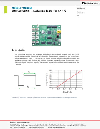
- 1. MODULE/MANUAL SMTAS08USBMINI – Evaluation board for SMT172 last update February 2, 2017 reference SMTAS08USB mini page 1/10 1. Introduction This document describes an 8 channel temperature measurement system: The New Smart temperature Acquisition System (SMTAS08usbmini). This system is based on the use of the Smart- temperature sensors SMT172. The SMT172 is a three terminal integrated temperature sensor with a duty cycle output. Two terminals are used for the power supply of and the third terminal carries the output signal. The output signal of the sensor is a duty-cycle-modulated square-wave signal (see Figure 1). Figure 1 (a) Output signal of the SMT172 temperature sensor, (b) Relation between the duty-cycle and the temperature.
- 2. SMTAS08USBMINI – Evaluation board for SMT172 last update February 2, 2017 Reference SMTAS08USBmini page 2/10 After measuring both t1 and t2, the temperature in °C can be calculated by a linear equation: = . − 68.9 Or a more accurate formula: Ɵ = -1.43 DC2+214.56 DC -68.60 DC = Duty Cycle Ɵ = temperature in °C The temperature sensors are sold separately from the SMTAS08usbmini board. The SMT172 temperature sensor is available in different encapsulations (TO18,TO92, TO220, etc), each with their specific properties Very important to point your attention to, is the accuracy of SMT172 sensors. The TO18 version yields the most accurate sensor and has an accuracy of 0.1 °C in a limited temperature range (-10 to 70 °C). The complete specification of the temperature sensor range is presented in the SMT172 datasheet, which should be consulted in conjunction with this document. The SMTAS08usbmini is equipped with an ARM Cortex-M3 STM32F103 microcontroller. An USB (Virtual COM port) interface offers external communication with the microcontroller. In turn, each of the sensors is powered by the microcontroller. How to install drivers on your personal computer see therefore our publication “USB to PC” which can be found in http://notes.smartec-sensors.com The microcontroller powers one of the eight sensors and measure the values of 16 cycle of t1 and t2 (2 DEMs), using an analog multiplexer (74HC4051), which is controlled by the microcontroller. This process is repeated for each of the sensors. After measurement of all required sensors the recalculated eight values of t1 and t2 are sent via USB port. The microcontroller captures 2 DEM cycles and calculate the averaged duty cycle. (For more information we refer to documents of SMT172). Each calculated average duty cycle is sent via USB port. A block diagram and a picture of the system PC-board are shown in Figure 2 and Figure 3, respectively.
- 3. SMTAS08USBMINI – Evaluation board for SMT172 last update February 2, 2017 Reference SMTAS08USBmini page 3/10 Figure 2 Functional block diagram Figure 3 A photograph of the SMTAS08usbmini system
- 4. SMTAS08USBMINI – Evaluation board for SMT172 last update February 2, 2017 Reference SMTAS08USBmini page 4/10 2. Quick start and functional check This document assumes SMTAS08usbmini board should be connected to a personal computer or a laptop. Any other device capable of handling USB CDC device could do the job just as well. In order to get the board running, a few things have to be prepared. Please find the hardware checklist below: - The SMTAS08usbmini board - One or more SMT172 sensors - A mini USB connecting cable - A PC or laptop running a terminal program for instance “Windows Hyper terminal” or “Putty” - Power supply (Optional, if you don’t want to use power from USB line) Since most of USB hosts (Laptops and PCs) can supply enough power to run the board and its connecting sensors through USB port, using of a separate power supply is not required. Anyway sometimes we don’t want to use power from USB host, e.g. in case of connecting the board to a tablet or Smart-Phone’s USB-host. In that case a power supply capable to deliver between 7 and 18 Volts (min 20 mA) is required and the “Power Select Jumper” on the board must be disconnected. By connecting the board to a computer, a new Virtual-COM device must be detected by the computer. If you connect the board for the first time, it is needed to install its driver. For installation of the USB-Driver software can be found on the Smartec website http://notes.smartec-sensors.com After connecting the parts together, measuring of temperatures can start. You can capture the measured data with a simple serial-port terminal software like Windows’s hyper terminal. Make sure the port number itself is chosen correctly (e.g. COM3). The com port’s parameters, (like Baud rate, parity …) are not required to be configured, just leave them by default values. After opening the port, type “m” and the DataStream should start flowing. More information about this will be given later but this is the fastest way to check whether the SMTAS08usbmini board is functioning correctly. Please refer to section 4 for the pin layout of the board and to the datasheet of the SMT172 for the sensor pin connections. In case no sensors are connected to the SMTAS08usbmini board all data will appear as “FFFF”. 3. Inside the SMTAS08 system - General The SMTAS08usbmini system can be used to measure up to 8 Smartec temperature sensors. The microcontroller measures the output signal of the selected sensor, provides the 5 V of 3.3 V power supply for the selected sensor and communicates with the outside digital world. Figure 4 shows the flowchart of the program in the microcontroller. A 20-pin JTAG ARM programming connector is available on the board, so the user is free to write his/her own program if desired.
- 5. SMTAS08USBMINI – Evaluation board for SMT172 last update February 2, 2017 Reference SMTAS08USBmini page 5/10 Figure 4 Simplified flowchart of program in the microcontroller
- 6. SMTAS08USBMINI – Evaluation board for SMT172 last update February 2, 2017 Reference SMTAS08USBmini page 6/10 - Self-heating of the temperature sensor Each sensor needs some power, no matter how little, which leads to an error in the temperature measurement. By switching off the power of the sensors that are not being sampled and by making sure the measurement duration of each sensor is as short as possible the effect of self-heating is very small. It is even smaller than the resolution of the sensor; so it can be neglected. Each of the eight sensors is only switched on for a period of maximum about 10 ms (16 period). In figure 5 the timing diagram of the subsequent sensors is depicted. With all sensors mounted, each sensor is being powered about 10% of time and when fewer sensors are mounted this percentage will increase. Figure 5 Timing diagram of subsequent sensors. (Times given in timing-diagram are typical) - Measurement accuracy The resolution (i.e. the accuracy that is determinable with sensor output duty cycle), depends on the number of samples taken. With the chosen sampling speed (72 MHz) and number of sampled cycles (16 cycle) a resolution of 0.0015 °C is obtained and at the same time the self-heating effect is minimized. The absolute accuracy of the all over measurement system still depends on the sensors (0.1 °C for the TO18, see datasheet of SMT172). 4. Circuit diagram and connections to the board -General In figure 6 the circuit diagram of the SMTAS08usbmini board is given. The board’s power both can supply by the USB connector or DC supply voltage in the range of 7 V to 18 V. It is selectable using the jumper on the board. The on-board voltage regulator provides the internal 3.3V power that is used for microcontroller. The power of sensors can both be supplied by 3.3V or 5V that is configurable by software. The 20-pin JTAG connector can be used to program costume programs for the microcontroller.
- 7. SMTAS08USBMINI – Evaluation board for SMT172 last update February 2, 2017 Reference SMTAS08USBmini page 7/10 Figure 6 Circuit diagram of the SMTAS08 system
- 8. SMTAS08USBMINI – Evaluation board for SMT172 last update February 2, 2017 Reference SMTAS08USBmini page 8/10 - Connector layout Connection to the SMTAS08usbmini board is implemented with 12 connectors: P1 ~ P8 3-pin header to connect 8 sensors Power 3-pin header for power supply USB Mini-USB B-type connector for communication with a PC PP2 JTAG connector CN9, Compatible with Segger’s J-Link® Connector Sync Synchronization signal, to view 8 cycle of sensor 1‘s output on a oscilloscope Figure 7Pinout of connectors on SMTAS08usb( top view) Warning: Never use an external power supply while the jumper is connected. 5. SMTAS08 software There are many ways to display results from the system. As an example, we will discuss a terminal program under Windows (Hyper Terminal/Putty). When you connect the SMTAS08usbmini board to a computer for the first time, a new USB device will be recognized and you will be asked to install the “USB Driver”. When the driver has been installed correctly, a new COM port will be recognized by the computer. It is a virtual COM port and will be available whenever you connect the board to the computer. See therefore our publication “USB to PC” in http://notes.smartec-sensors.com P4 P3 P2 P1 P8 P7 P6 P5
- 9. SMTAS08USBMINI – Evaluation board for SMT172 last update February 2, 2017 Reference SMTAS08USBmini page 9/10 Hyper Terminal/Putty A terminal program like Hyper Terminal or Putty under Windows can easy display the measurement results via the serial port of the PC (even virtual). Remember that the COM port is a virtual one and in fact the connection is USB. The data will be transferred vial USB, so although the COM configuration parameters (like baud rate, data bit, stop bit, parity, etc.) are configurable, it is not necessary to configure them. The virtual COM communication is chosen for being more compatible and user-friendly in PC side. Once the communication between the microcontroller and the PC is established, you can get help information by typing “h”. The following will be displayed: S M T A S 8 T E M P E R A T U R E M E A S U R E M E N T S Y S T E Mrn Version :DEM" h -> Help function m -> Infinite measurement cycle ! -> Set Measurement Rate: Continue (default value) @ -> Set Measurement Rate: each 5 seconds # -> Set Measurement Rate: each 20 seconds $ -> Set Measurement Rate: each 60 seconds % -> Set Measurement Rate: each 10 minutes 1 -> First sensor, single measurement 2 -> First two sensors, single measurement 3 -> First three sensors, single measurement 4 -> First four sensors, single measurement 5 -> First five sensors, single measurement 6 -> First six sensors, single measurement 7 -> First seven sensors, single measurement 8 -> First eight sensors, single measurement s -> Stop v -> Power sensors by 3.3V ( not for SMT160) V -> Power sensors by 5 V Please Make a Choice : As soon as you press “m” or a digit between “1” and “8”, the board will start sending data. The data format is Hexadecimal. For each sensor, both t1 and t2 are represented by four hexadecimal ASCII digits, separated by ‘ ‘ (space) and followed by “n” or “CR/LF” at the end. In case that there is no sensor connected to a selected position, or when a selected sensor does not transmit a period- modulated output signal, this will be detected by the microcontroller, which will send “FFFF” for both t1 and t2.
- 10. SMTAS08USBMINI – Evaluation board for SMT172 last update February 2, 2017 Reference SMTAS08USBmini page 10/10 The board measures 16 cycle of PWM (2 DEM cycle) and average DEM using method A, and represent just one t1 and t2, it also normalize t2 to maximum correct value witch is “FFFE”. Below you find a typical example of a terminal output. As you can see, sensor 8 is not connected. Figure 8 Typical example of a Terminal program output (Sensor 8 not connected) To obtain the corresponding temperature, the values for t1 and t2 have to be substituted in formula (1/2). A terminal program cannot do this calculation, but gives you a convenient way of displaying the board data. Included with the board is also a LabVIEW program, which will do the calculations as well and display the actual temperatures. Delphi program A Delphi program is available on our website http://notes.smartec-sensors.com This program can be used also to display the temperatures of the connected sensors. The program can store also the measured data in a cvs file for later use. 6. Ordering information SMTAS08USBmini Temperature Acquisition System for 8 Smartec temperature sensors (USB). SMTAS04USBmini Temperature Acquisition System for 4 Smartec temperature sensors (USB). SMT172-TO18 Smartec temperature sensor in TO18 encapsulation (metal can) SMT172-TO92 Smartec temperature sensor in TO92 encapsulation (commercial) SMT172-TO220 Smartec temperature sensor in TO220 encapsulation SMT172-SOIC-8 Smartec temperature sensor in SOIC8 SMT172-SOT223 Smartec temperature sensor in SOT223 housing SMT172-HEC Smartec temperature sensor as small hybrid element