
Recommended
Recommended
More Related Content
What's hot
What's hot (20)
Similar to SMC T-Series Tubing
Similar to SMC T-Series Tubing (20)
Recently uploaded
Recently uploaded (20)
SMC T-Series Tubing
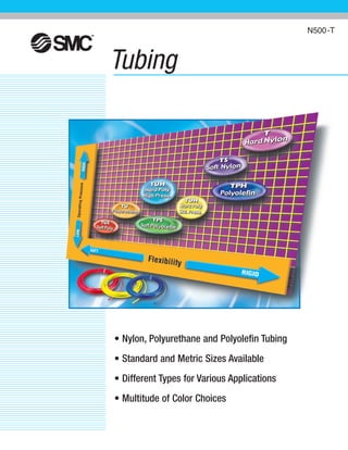
- 1. Tubing • Nylon, Polyurethane and Polyolefin Tubing • Standard and Metric Sizes Available • Different Types for Various Applications • Multitude of Color Choices N500-T
- 2. SMC is widely recognized as a world leader in motion automation technology. Our worldwide reputation for quality and reliability was earned through our commitment to research and development, engineering, sales support, and customer service. We are truly a global company with a local focus to ensure our customers needs are met wherever their business takes them. We offer a comprehensive line of technologically advanced products. This product offering now includes a tubing product line that was developed and manufactured to meet SMC’s strict quality standards. 12 different types of tubing for general industrial applications are offered as well as D.O.T. tubing and tubing made of Teflon® . To address the different needs of industry, we offer Nylon and Polyolefin tubing in at least 2 different hardness ratings, and our Polyurethane tubing is available in 4 hardness ratings. To maintain the highest quality possible, the outside diameter as well as the wall thickness of SMC tubing are inspected during the manufacturing process for dimensional accuracy. If your application happens to be spot welding, clean room, robotics, heavy vehicle or motion automation, SMC not only has the right tubing, but also offers it in Standard and Metric sizes in a multitude of colors. Contact your SMC representative at 1-800-SMC-SMC1 or visit us on the worldwide web at www.smcusa.com. Teflon® is a registered trademark of DuPont. All rights reserved. SMC is widely recognized as a world leader in motion automation technology.
- 3. Table Of Contents Tubing Products Nylon Tubing Information . . . . . . . . . . . . . . . . . . . . . . . . . . . . . . . . . . . . . . . . . . . . . . . 4 Series TIA . . . . . . . . . . . . . . . . . . . . . . . . . . . . . . . . . . . . . . . . . . . . . . . . . . . . . . . . . . 5 Series T . . . . . . . . . . . . . . . . . . . . . . . . . . . . . . . . . . . . . . . . . . . . . . . . . . . . . . . . . . . . 6 Series TS/TISA . . . . . . . . . . . . . . . . . . . . . . . . . . . . . . . . . . . . . . . . . . . . . . . . . . . . . . 7 Polyurethane Tubing Information . . . . . . . . . . . . . . . . . . . . . . . . . . . . . . . . . . . . . . . . . 8 Series TIUB . . . . . . . . . . . . . . . . . . . . . . . . . . . . . . . . . . . . . . . . . . . . . . . . . . . . . . . . . 9 Series TU . . . . . . . . . . . . . . . . . . . . . . . . . . . . . . . . . . . . . . . . . . . . . . . . . . . . . . . . . . 10 Series TUS . . . . . . . . . . . . . . . . . . . . . . . . . . . . . . . . . . . . . . . . . . . . . . . . . . . . . . . . 11 Series TUH - Standard Pressure . . . . . . . . . . . . . . . . . . . . . . . . . . . . . . . . . . . . . . . . 12 Series TUH - High Pressure . . . . . . . . . . . . . . . . . . . . . . . . . . . . . . . . . . . . . . . . . . . . 13 Series TCU . . . . . . . . . . . . . . . . . . . . . . . . . . . . . . . . . . . . . . . . . . . . . . . . . . . . . . . . 14 Series TFU . . . . . . . . . . . . . . . . . . . . . . . . . . . . . . . . . . . . . . . . . . . . . . . . . . . . . . . . 15 Clean Series Tubing 10-TU, 10-TCU, 10-TFU . . . . . . . . . . . . . . . . . . . . . . . . . . . . . . . . 16 Polyolefin Tubing, Series TPH, TPS . . . . . . . . . . . . . . . . . . . . . . . . . . . . . . . . . . . . . . . 17 Antistatic Tubing Series TAS . . . . . . . . . . . . . . . . . . . . . . . . . . . . . . . . . . . . . . . . . . . 18 Antistatic Tubing Series TAU . . . . . . . . . . . . . . . . . . . . . . . . . . . . . . . . . . . . . . . . . . . 19 Flame Resistant Series TIRS/TRS . . . . . . . . . . . . . . . . . . . . . . . . . . . . . . . . . . . . . . . . 20 Flame Resistant Series TRB . . . . . . . . . . . . . . . . . . . . . . . . . . . . . . . . . . . . . . . . . . . . 21 Flame Resistant Series TRBU . . . . . . . . . . . . . . . . . . . . . . . . . . . . . . . . . . . . . . . . . . 22 How To Install TRB/TRBU Tubing . . . . . . . . . . . . . . . . . . . . . . . . . . . . . . . . . . . . . . . . 23 Accessories Series TM, TG . . . . . . . . . . . . . . . . . . . . . . . . . . . . . . . . . . . . . . . . . . . . . 24 Accessories Series TK, TKS, TB-3VS . . . . . . . . . . . . . . . . . . . . . . . . . . . . . . . . . . . . . . 25 Chemical Resistance Chart - Nylon 12 . . . . . . . . . . . . . . . . . . . . . . . . . . . . . . . . . . . . 26 Chemical Resistance Chart - Polyurethane . . . . . . . . . . . . . . . . . . . . . . . . . . . . . . . . 27 Chemical Resistance Chart - Polyolefin . . . . . . . . . . . . . . . . . . . . . . . . . . . . . . . . . . . 28 Safety Instructions . . . . . . . . . . . . . . . . . . . . . . . . . . . . . . . . . . . . . . . . . . . . . . . . . . 29 Precautions . . . . . . . . . . . . . . . . . . . . . . . . . . . . . . . . . . . . . . . . . . . . . . . . . . . . . . . . 30 Custom Options . . . . . . . . . . . . . . . . . . . . . . . . . . . . . . . . . . . . . . . . . . . . . . . . . . . . . 31
- 4. 4 Nylon Tubing Nylon was developed more than half a century ago and is considered to be the first man-made thermoplastic available. Deemed a rugged engineering plastic, its properties make it an ideal choice for a variety of applications. Nylon does not depend on moisture for flexibility and will not become brittle or swell because of water. therefore, it has excellent low moisture absorption and dimensional stability characteristics. Nylon tubing for pneumatic applications is made from Nylon 11, and more recently Nylon 12. Nylon 12 has virtually the same physical properties and performance as Nylon 11. SMC mainly uses Nylon 12. Nylon 11 is offered by request. Properties L Dimensional stability L Light weight L Low moisture absorption L Wide temperature range L Elastic memory L High abrasion resistance L High impact resistance L Good flexibility L High thermal resistance L Broad chemical resistance
- 5. 5 Nylon TubingSeries TIA (Inch) Dimensions Specifications Inch Model Tube OD (Inches) Tube ID (Inches) Min. bending radius (Inches) TIA01 TIA05 TIA07 TIA11 TIA13 1/8 5/32 3/16 1/4 5/16 3/8 1/2 0.086 0.098 0.137 0.18 0.236 0.275 0.378 0.59 0.51 0.79 1.18 1.89 2.36 2.95 Series TIA *For 5/32 and 5/16 tubing, please refer to 4mm (T0425) and 8mm (T0806) tubing on page 6. Operating Fluid Air, Water Max. Operating Pressure 220 psi (1.5MPa) at 68˚F (20˚C) Burst Pressure Refer to burst pressure characteristic chart Operating Temperature Air: -4˚ to 140˚F (-20˚ to 60˚C) Water: 40˚ to 105˚F (5˚ to 40˚C) Material Nylon 12 Hardness Shore D 70 Packaging Design Length 100ft 500ft 1000ft 1/8 5/32 3/16 1/4 5/16 3/8 1/2 Bag Refer to Bag Bag Refer to Bag Bag Bag 4mm Bag Bag 8mm Reel Reel Reel Tubing Reel Reel Tubing Reel Reel Inch Size Tubing How To Order Burst Pressure Characteristics Chart TIA 07 B -- 33 Symbol 01 See Note* 05 07 See Note* 11 13 1/8 5/32 3/16 1/4 5/16 3/8 1/2 Nylon Inch Size Color Indication Tube Size Symbol B W R BU Y G Black White Red Blue Yellow Green Color Symbol 33 153 305 100ft 500ft 1000ft Roll Size Length Per Roll Longer lengths available upon request Note* - For 5/32 and 5/16 size tubing, please refer to 4mm (T0425) and 8mm (T0806) “How to Order” information on page 6 Caution 1. Can be used with general industrial water. For other fluids, please consult SMC. 2. Max. operating pressure and minimum bending radius are measured at 68˚F. 3. When using tubing with SMC fittings, the chemical resistance of the fitting has to be investigated as well. 0 2175 1885 1595 1305 1015 725 435 145 -4 32 68 104 140 BurstPressurepsi Operating Temperature ˚F For general use Max. operating pressure
- 6. 6 Nylon Tubing Series T (Metric) Dimensions Metric Model Tube OD (mm) Tube ID (mm) Min. bending radius (mm) T0425 T0403 T0604 T0645 T0806 T1075 T1209 T1613 4 4 6 6 8 10 12 16 2.5 3 4 4.5 6 7.5 9 13 13 25 24 36 48 60 75 100 Series T Packaging Design Length 20m 100m 4mm 6mm 8mm 10mm 12mm 16mm Bag Bag Bag Bag Bag Bag Bag Bag Bag Box Box Reel Metric Size Tubing How To OrderBurst Pressure Characteristics Chart T 0604 B -- 20 Symbol 0425 0403 0604 0645 0806 1075 1209 1613 4mm (5/32”) 4mm 6mm 6mm 8mm (5/16”) 10mm 12mm 16mm Nylon Metric Size Color Indication Tube Size Symbol B W R BU Y G Black White Red Blue Yellow Green Color Symbol 20 100 20m 100m Roll Size Length Per Roll Longer lengths available upon request Caution 1. Can be used with general industrial water. For other fluids, please consult SMC. 2. Max. operating pressure and minimum bending radius are measured at 68˚F. 3. When using tubing with SMC fittings, the chemical resistance of the fitting has to be investigated as well. 0 2175 1885 1595 1305 1015 725 435 145 -4 32 68 104 140 BurstPressurepsi Operating Temperature ˚F For general use Max. operating pressure T0425, T0604 f f f Other than T0425, T0604 Specifications Operating Fluid Air, Water Max. Operating Pressure 220 psi (1.5MPa) at 68˚F (20˚C) Burst Pressure Refer to burst pressure characteristic chart Operating Temperature Air: -4˚ to 140˚F (-20˚ to 60˚C) Water: 40˚ to 105˚F (5˚ to 40˚C) Material Nylon 12 Hardness Shore D 70
- 7. 7 Soft Nylon Tubing Dimensions Specifications Inch Model Tube OD (Inches) Tube ID (Inches) Min. bending radius (Inches) TISA01 TISA05 TISA07 TISA11 TISA13 1/8 5/32 3/16 1/4 5/16 3/8 1/2 0.086 0.098 0.137 0.18 0.236 0.275 0.378 0.47 0.47 0.59 0.91 0.91 1.18 1.57 Series TISA Metric Model Tube OD (mm) Tube ID (mm) Min. bending radius (mm) TS0425 TS0604 TS0806 TS1075 TS1209 TS1612 4 6 8 10 12 16 2.5 4 6 7.5 9 12 12 15 23 27 31 60 Series TS *For 5/32 and 5/16 tubing, please refer to 4mm and 8mm tubing. Operating Fluid Air Max. Operating Pressure 145 psi (1MPa) at 68˚F (20˚C) Burst Pressure Refer to burst pressure characteristic chart Operating Temperature -4˚ to 140˚F (-20˚ to 60˚C) Material Nylon 12 Hardness Shore D 56 Packaging Design Length 20m 100m 1/8 5/32 3/16 1/4 5/16 3/8 1/2 Bag Refer to Bag Bag Refer to Bag Bag Reel 4mm Reel Reel 8mm Reel Reel Inch Size Tubing Packaging Design Length 20m 100m 4mm 6mm 8mm 10mm 12mm 16mm Bag Bag Bag Bag Bag Bag Bag Bag Bag Box Box Reel Metric Size Tubing How To Order Burst Pressure Characteristics Chart TISA 07 B -- 100 Symbol 01 See Note* 05 07 See Note* 11 13 1/8 5/32 3/16 1/4 5/16 3/8 1/2 Soft Nylon Inch Size Color Indication Tube Size Symbol B W R BU Y G Black White Red Blue Yellow Green Color Symbol 20 100 20m 100m* Roll Size Length Per Roll Longer lengths available upon request *Black & White Only Note* - For 5/32 and 5/16 size tubing, please refer to 4mm and 8mm “How to Order” information TS 0604 W -- 100 Symbol 0425 0604 0806 1075 1209 1612 4mm 6mm 8mm 10mm 12mm 16mm Soft Nylon Metric Size Color Indication Tube Size Symbol B W R BU Y G Black White Red Blue Yellow Green Color Symbol 20 100 20m 100m* Roll Size Length Per Roll Longer lengths available upon request *Black & White Only Caution 1. Do not use with general industrial water. Water will cause the O.D. to shrink, which could cause leaks or the possible release of the tubing from the one-touch® fitting. 2. Max. operating pressure and minimum bending radius are measured at 68˚F. 3. When using tubing with SMC fittings, the chemical resistance of the fitting has to be investigated as well. 0 1305 1015 725 435 145 -4 32 68 104 140 BurstPressurepsi Operating Temperature ˚F All-purpose tubing using soft Nylon compound for added flexibility H H H H H H H H H Max. operating pressure Other than (TS0425, TS0604) Max. operating pressure (TS0425, TS0604) TS0425, TS0604 Other than TS0425, TS0604 Series TS, TISA
- 8. 8 Polyurethane Tubing Polyurethane tubing is fast becoming the ideal choice for pneumatic applications. It combines the elasticity of rubber with the chemical resistance normally reserved for plastics. Polyurethane can be put into two classifications, ester based and ether based. SMC offers both. Ether based polyurethane is the preferred tubing material for general pneumatic applications due to its immunity to hydrolysis and its higher resistance to fungus and microorganism attacks. The Ester based polyurethane is a stronger compound but tends to hydrolyze with moisture. This hydrolysis process will degrade the material over time. SMC’s primary line of polyurethane tubing is ether based, made from the highest quality compound available, to ensure the longest tubing life. The ester based TUH series is the exception. This product line was developed to take advantage of the greater strength offered by this compound. Properties L Cut resistant L Kink resistant L Excellent memory L Tear resistant L Wide temperature range L Abrasion resistant L Low compression set L Extreme flexibility L Low gas permeability L Good chemical resistance
- 9. 9 Polyurethane TubingSeries TIUB (Inch) Dimensions Inch Model Tube OD (Inches) Tube ID (Inches) Min. bending radius (Inches) TIUB01 TIUB05 TIUB07 TIUB11 TIUB13 1/8 5/32 3/16 1/4 5/16 3/8 1/2 0.08 0.1 0.13 0.17 0.2 0.25 0.33 0.39 0.39 0.6 0.91 0.79 1.06 1.38 Series TIUB *For 5/32 and 5/16 tubing, please refer to 4mm and 8mm tubing on page 10. Packaging Design Length 66ft 100ft 500ft 1000ft 1/8 5/32 3/16 1/4 5/16 3/8 1/2 Bag Refer to Bag Bag Refer to Bag Bag Bag 4mm Bag Bag 8mm Reel Reel Bag tubing Bag Bag tubing Reel Reel Reel Reel Reel Reel Reel Inch Size Tubing How To Order Burst Pressure Characteristics Chart TIUB 05 BU -- 33 Symbol 01 See Note* 05 07 See Note* 11 13 1/8 5/32 3/16 1/4 5/16 3/8 1/2 Polyurethane Inch Size Color Indication Tube Size Symbol B W R BU Y G C YR Black White Red Blue Yellow Green Clear Orange Color Symbol 20 331 1531 3051 66ft 100ft 500ft 1000ft Roll Size Length Per Roll Longer lengths available upon request 1 Stocked item Note* - For 5/32 and 5/16 size tubing, please refer to 4mm and 8mm “How to Order” information on page 10. *- Quick ship colors indicated, see chart on page 31 for other available colors Caution 1. Can be used with general industrial water. For other fluids, please consult SMC. 2. Max. operating pressure and minimum bending radius are measured at 68˚F. 3. When using tubing with SMC fittings, the chemical resistance of the fitting has to be investigated as well. 0 711 569 427 285 142 -4 32 70 105 140 BurstPressurepsi Operating Temperature ˚F For general use H H Max. operating pressure Burst pressure * Specifications Operating Fluid Air, Water Max. Operating Pressure 115 psi (0.8MPa) at 68˚F (20˚C) Burst Pressure Refer to burst pressure characteristic chart Operating Temperature Air: -4˚ to 140˚F (-20˚ to 60˚C) Water: 40˚ to 105˚F (5˚ to 40˚C) Material Polyurethane Hardness Shore A 95
- 10. 10 Polyurethane Tubing Series TU (Metric) Dimensions Metric Model Tube OD (mm) Tube ID (mm) Min. bending radius (mm) TU0425 TU0604 TU0805 TU1065 TU1208 4 6 8 10 12 2.5 4 5 6.5 8 10 15 20 27 35 Series TU Packaging Design Length 20m 33m 100m 153m 305m 500m 4mm 6mm 8mm 10mm 12mm Bag Bag Bag Bag Bag Bag — Bag — — Bag Bag Bag Box Box Bag — Box — — Reel — Reel — — Reel Reel Reel — — Metric Size Tubing How To OrderBurst Pressure Characteristics Chart 1 Stocked item * 4mm, 6mm, 8mm TU 0604 BU -- 20 Symbol 0425 0604 0805 1065 1208 4mm (5/32”) 6mm 8mm (5/16”) 10mm 12mm Metric Size Color Indication Tube Size Symbol B W R BU Y G C YR Black White Red Blue Yellow Green Clear Orange Color Symbol 201 33 1001 153 305 5001 20m 33m 100m 153m 305m 500m* Roll Size Length Per Roll Longer lengths available upon request Caution 1. Can be used with general industrial water. For other fluids please consult SMC. 2. Max. operating pressure and minimum bending radius are measured at 68˚F. 3. When using tubing with SMC fittings, the chemical resistance of the fitting has to be investigated as well. 0 711 569 427 285 142 -4 32 70 105 140 BurstPressurepsi Operating Temperature ˚F For general use H H Max. operating pressure Burst pressure * Polyurethane Specifications Operating Fluid Air, Water Max. Operating Pressure 115 psi (0.8MPa) at 68˚F (20˚C) Burst Pressure Refer to burst pressure characteristic chart Operating Temperature Air: -4˚ to 140˚F (-20˚ to 60˚C) Water: 40˚ to 105˚F (5˚ to 40˚C) Material Polyurethane Hardness Shore A 95 *- Quick ship colors indicated, see chart on page 31 for other available colors
- 11. 11 Soft Polyurethane TubingSeries TUS Dimensions Specifications Metric Model Tube OD (mm) Tube ID (mm) Min. bending radius (mm) TUS0425 TUS0604 TUS0805 TUS1065 TUS1208 4 6 8 10 12 2.5 4 5 6.5 8 8 15 15 22 29 Series TUS Operating Fluid Air Max. Operating Pressure 87 psi (0.6MPa) at 68˚F (20˚C) Burst Pressure Refer to burst pressure characteristic curve Operating Temperature -4˚ to 140˚F (-20˚ to +60˚C) Material Polyurethane Hardness Shore A 89 Packaging Design Length 20m 100m 4mm 6mm 8mm 10mm 12mm Bag Bag Bag Bag Bag Reel Reel Reel Reel Reel Metric Size Tubing How To Order Burst Pressure Characteristics Chart TUS 1065 BU -- 100 Symbol 0425 0604 0805 1065 1208 4mm 6mm 8mm 10mm 12mm Metric Size Color Indication Tube Size Symbol B W R BU Y G N YB Black White Red Blue Yellow Green Translucent Yellow Brown Color Symbol 20 100 20m 100m Roll Size Length Per Roll Longer lengths available upon request Caution 1. Do not use with general industrial water. 2. Max. operating pressure and minimum bending radius are measured at 68˚F. 3. When using tubing with SMC fittings, the chemical resistance of the fitting has to be investigated as well. 4. Always use inner sleeve (Series TJ) in safety circuit or critical area. 0 435 290 145 -4 32 68 104 140 BurstPressurepsi Operating Temperature ˚F Suitable for environments where extreme flexibility is required HH Max. operating pressure Burst pressure Soft Polyurethane Series TJ Inner Sleeve TUS related accessories Model Part No. TJ-0425 TJ-0604 TJ-0805 TJ-1065 TJ-1208 Length 18 19 20.5 23 24 Applicable Tube Model TUS0425 TUS0604 TUS0805 TUS1065 TUS1208 Specifications Material Wall thickness C2700T (Electroless nickel plating) 0.2mm Reinforces soft polyurethane tubing. Insert an inner sleeve into the end of soft polyurethane tubing when used with a One-TouchTM fitting. Soft Polyurethane Tubing Inner Sleeve One-TouchTM Fitting
- 12. 12 Hard Polyurethane Tubing Series TUH Dimensions Specifications Metric Model Tube OD (mm) Tube ID (mm) Min. bending radius (mm) TUH0428 TUH0644 TUH0858 TUH1073 TUH1288 4 6 8 10 12 2.8 4.4 5.8 7.3 8.8 10 18 24 30 36 Series TUH Operating Fluid Air Max. Operating Pressure 115 psi (0.8MPa) at 68˚F (20˚C) Burst Pressure Refer to burst pressure characteristic chart Operating Temperature -4˚ to 140˚F (-20˚ to 60˚C) Material Polyurethane Hardness Shore D 57 Packaging Design Length 20m 100m 4mm 6mm 8mm 10mm 12mm Bag Bag Bag Bag Bag Bag Bag Bag Box Box Metric Size Tubing How To Order TUH 0644 BU -- 100 Symbol 0428 0644 0858 1073 1288 4mm 6mm 8mm 10mm 12mm Metric Size Color Indication Tube Size Symbol B W BU N Black White Blue Translucent Color Symbol 20 100 20m 100m Roll Size Length Per Roll Longer lengths available upon request Caution 1. Do not use with general industrial water due to the occurrence of hydrolysis. 2. Max. operating pressure and minimum bending radius are measured at 68˚F. 3. When using tubing with SMC fittings, the chemical resistance of the fitting has to be investigated as well. Standard Increased flow capability as compared to SMC’s standard polyurethane tubing Hard Polyurethane Bend the tube into U-form at a temperature of 68˚F. Fix one end and close loop gradually. Measure 2R when the tubing starts to kink. Note) Cannot be used for water due to the occurrence of hydrolysis. Fixedend Burst Pressure Characteristics Chart 0 725 580 435 290 145 -4 32 68 104 140 BurstPressurepsi Operating Temperature ˚F H H Max. operating pressure H Burst pressure
- 13. 13 Hard Polyurethane TubingSeries TUH Dimensions Specifications Metric Model Tube OD (mm) Tube ID (mm) Min. bending radius (mm) TUH0425 TUH0604 TUH0805 TUH1065 TUH1208 4 6 8 10 12 2.5 4 5 6.5 8 10 15 20 27 35 Series TUH Operating Fluid Air Max. Operating Pressure 145 psi (1.0MPa) at 68˚F (20˚C) Burst Pressure Refer to burst pressure characteristic chart Operating Temperature -4˚ to 140˚F (-20˚ to 60˚C) Material Polyurethane Hardness Shore D 57 Packaging Design Length 20m 100m 4mm 6mm 8mm 10mm 12mm Bag Bag Bag Bag Bag Bag Bag Bag Box Box Metric Size Tubing How To Order TUH 0604 BU -- 100 Symbol 0425 0604 0805 1065 1208 4mm 6mm 8mm 10mm 12mm Metric Size Color Indication Tube Size Symbol B W BU N Black White Blue Translucent Color Symbol 20 100 20m 100m Roll Size Length Per Roll Longer lengths available upon request Caution 1. Do not use with general industrial water due to the occurrence of hydrolysis. 2. Max. operating pressure and minimum bending radius are measured at 68˚F. 3. When using tubing with SMC fittings, the chemical resistance of the fitting has to be investigated as well. High Pressure Operating pressure is 25% higher than standard TUH tubing Hard Polyurethane Bend the tube into U-form at a temperature of 68˚F. Fix one end and close loop gradually. Measure 2R when the tubing starts to kink. Fixedend Burst Pressure Characteristics Chart 0 725 870 1015 580 435 290 145 -4 32 68 104 140 BurstPressurepsi Operating Temperature ˚F H H Max. operating pressure H Burstpressure Note) Can not be used for water due to the occurrence of hydrolysis
- 14. 14 Polyurethane Coil Tubing Series TCU Dimensions Specifications Metric Model Number of Tubes Tube OD (mm) Tube ID (mm) 0425B-1 0425B-2 0425B-3 0604B-1 0604B-2 0604B-3 0805B-1 1 2 3 1 2 3 1 4 4 4 6 6 6 8 2.5 2.5 2.5 4 4 4 5 TCU TCU TCU TCU TCU TCU TCU Series TCU Operating Fluid Air Max. Operating Pressure 115 psi (0.8MPa) at 68˚F (20˚C) Burst Pressure Refer to burst pressure characteristic chart Operating Temperature -4˚ to 140˚F (-20˚ to 60˚C) Material Polyurethane Hardness Shore A 95 How To Order Coil Dimensions Made To Order Burst Pressure Characteristics Chart TCU 0425 B -- 2 Symbol 0425 0604 0805 4mm 6mm 8mm Coil Tubing Metric Size Color Indication Tube Size Symbol B C BU W Y R G YR Black Clear Blue White Yellow Red Green Orange Color Symbol 1 2 3 1 2 3 Number of Tubes Number of Tubes Caution 1. Contact SMC regarding other fluids. 2. Max. operating pressure and minimum bending radius are measured at 68˚F. 3. When using tubing with SMC fittings, the chemical resistance of the fitting has to be investigated as well. 0 725 580 435 290 145 -4 32 68 104 140 BurstPressurepsi Operating Temperature ˚F Ideal for use with robotics and pneumatic pick and place applications Specifications Part No. Tube Size (mm) O.D. I.D. L ØD Dimension of Coil (mm) Number of Tubes Number of Coil Windings Per Tube Length Maximum Operating Length (m) TCU0425B-1 TCU0425B-2 TCU0425B-3 TCU0604B-1 TCU0604B-2 TCU0604B-3 TCU0805B-1 4 6 8 2.5 210 280 265 1 2 3 1 2 3 1 52 35 22 54 27 17 41 1.5 1 2 1.5 1 2 4 325 18 28 24 37 31 305 3305 Change of Coil Turns / Color Change H HHMax. operating pressure Burst pressure Part No. Tube Size (mm) O.D. I.D. L* ØD Dimension of Coil (mm) Number of Tubes Number of Coil Windings Per Tube Length Maximum Operating Length (mm) TCU0425❒-1-N-X6 TCU0425❒-2-N-X6 TCU0425❒-3-N-X6 TCU0604❒-1-N-X6 TCU0604❒-2-N-X6 TCU0604❒-3-N-X6 4 6 2.5 N X 4 N X 8 N X 12 N X 6 N X 12 N X 18 1 2 3 1 2 3 3 to 90 3 to 90 3 to 63 3 to 90 3 to 66 3 to 44 LX5.9+200 LX4.4+200 LX2.9+200 LX5.3+200 LX3.8+200 LX2.5+200 4 18 28 28 24 37 37 TCU0805❒-1-N-X6 TCU0805❒-2-N-X6 TCU1065❒-1-N-X6 TCU1065❒-2-N-X6 TCU1208❒-1-N-X6 TCU1208❒-2-N-X6 ❒ = B (Black), W (White), R (Red), BU (Blue), Y (Yellow), G (Green), C (Clear), YR (Orange) Consult SMC for detailed specifications,dimensions and delivery. *L is calculated by the number of coils (N) X O.D. 8 12 5 N X 8 N X 16 N X 10 N X 20 N X 12 N X 24 1 2 1 2 1 2 3 to 90 3 to 40 3 to 45 3 to 35 3 to 35 3 to 30 LX5.2+200 LX3+200 LX5+200 LX3+200 LX5+200 LX3+200 8 10 6.5 31 42 52 52 67 67 100 (Max. operating length) L 100 ØD Tube fastener (Multi-tube only) *Dimensions subject to change due to material
- 15. 15 Polyurethane Flat TubingSeries TFU Dimensions Specifications Metric Number of Tubes Tube OD (mm) Tube ID (mm) TFU TFU TFU TFU TFU TFU 0425B-2 0425B-3 0604B-2 0604B-3 0805B-2 0805B-3 2 3 2 3 2 3 4 4 6 6 8 8 2.5 2.5 4 4 5 5 Series TFU Operating Fluid Air Max. Operating Pressure 115 psi (0.8MPa) at 68˚F (20˚C) Burst Pressure Refer to burst pressure characteristic chart Operating Temperature -4˚ to 140˚F (-20˚ to 60˚C) Material Polyurethane Hardness Shore A 95 Made to Order 4 2.5 6 4 8 5 10 6.5 12 8 TFU0425 TFU0604 TFU0805 TFU1065 TFU1208 2 3 4 5 6 7 8 Number of Tubes 1. Color Change (10m roll) Suffix “X4” to the end of the part number. Ex.) TFU0604BU-2-10- X4 Note) W: White, R: Red, BU: Blue, Y: Yellow, G: Green, C: Transparent, YR: Orange (All tubes are same color) Suffix “X3” to the end of the part number. Ex.) TFU0425B-2-50-X3, TFU0425BU-3-100- X3 Suffix “X4” to the end of the part number. Ex.) TFU0604B-4-10-X4, TFU0604YR-4-10- X4 2. Longer roll length (50m or 100m roll) 3. Number of Tubes (10m roll) Model Tube O.D. Tube I.D. How To Order Burst Pressure Characteristics Chart TFU 0425 B -- 2 Symbol 0425 0604 0805 4mm 6mm 8mm Flat Tubing Consult SMC for detailed specifications, dimensions and delivery. : 10m roll : 50m roll : 100m roll Metric Size Color Indication Tube Size Symbol B Black Color Symbol 2 3 2 3 Number of Tubes Number of Tubes Caution 1. Contact SMC regarding other fluids. 2. Max. operating pressure is measured at 68˚F. 3. When using tubing with SMC fittings, the chemical resistance of the fitting has to be investigated as well. 0 725 580 435 290 145 -4 32 68 104 140 BurstPressurepsi Operating Temperature ˚F Eliminates the need for jacketing or spiral wrapping of multiple tubes Max. operating pressure Burst pressure Model 8 Tube Custom Order
- 16. Clean Series Tubing 16 Specifications Operating Fluid Air, Water Max. Operating Pressure 115 psi (0.8MPa) at 68˚F (20˚C) Burst Pressure Refer to burst pressure characteristic chart Operating Temperature Air: -4˚ to 140˚F (-20˚ to 60˚C) Water: 40˚ to 105˚F (5˚ to 40˚C) Material Polyurethane Hardness Shore A 95 Dimensions Metric Tube OD (mm) Tube ID (mm) Min. bending radius (mm) 10-TU0425 10-TU0604 10-TU0805 10-TU1065 10-TU1208 4 6 8 10 12 2.5 4 5 6.5 8 10 15 20 27 35 Series TU Model How To Order 10 - TU 0604 BU -- 20 Clean Series Metric Size Color Indication Length Per Roll Symbol 0425 0604 0805 1065 1208 4mm 6mm 8mm 10mm 12mm Tube Size Symbol 20 20m Roll SizeSymbol B W R BU Y G C YR Black White Red Blue Yellow Green Clear Orange Color Polyurethane Tubing Series 10-TU Specifications Operating Fluid Air Max. Operating Pressure 115 psi (0.9MPa) at 68˚F (20˚C) Burst Pressure Refer to burst pressure characteristic chart Operating Temperature -4˚ to 140˚F (-20˚ to 60˚C) Material Polyurethane Hardness Shore A 95 Dimensions Metric Number of tubes Tube OD (mm) Tube ID (mm) 10-TCU 10-TCU 10-TCU 10-TCU 10-TCU 10-TCU 10-TCU 0425B-1 0425B-2 0425B-3 0604B-1 0604B-2 0604B-3 0805B-1 1 2 3 1 2 3 1 4 4 4 6 6 6 8 2.5 2.5 2.5 4 4 4 5 Series TCU Model How To Order 10 - TCU 0425 B -- 2 Clean Series Metric Size Color Indication Number of Tubes Symbol 0425 0604 0805 4mm 6mm 8mm Tube Size Symbol 1 2 3 1 2 3 Number of TubesSymbol B Black Color Polyurethane Coiled Tubing Series 10-TCU Specifications Operating Fluid Air Max. Operating Pressure 115 psi (0.9MPa) at 68˚F (20˚C) Burst Pressure Refer to burst pressure characteristic chart Operating Temperature -4˚ to 140˚F (-20˚ to 60˚C) Material Polyurethane Hardness Shore A 95 Dimensions Metric Number of tubes Tube OD (mm) Tube ID (mm) 10-TFU 10-TFU 10-TFU 10-TFU 10-TFU 10-TFU 0425B-2 0425B-3 0604B-2 0604B-3 0805B-2 0805B-3 2 3 2 3 2 3 4 4 6 6 8 8 2.5 2.5 4 4 5 5 Series TFU Model How To Order 10 - TFU 0425 B -- 2 Clean Series Metric Size Color Indication Number of Tubes Symbol 0425 0604 0805 4mm 6mm 8mm Tube Size Symbol 2 3 2 3 Number of TubesSymbol B Black Color Polyurethane Flat Tubing Series 10-TFU
- 17. 17 Polyolefin Tubing Dimensions Specifications Metric Tube OD (mm) Tube ID (mm) Min. bending radius (mm) TPS0425 TPS0604 TPS0805 TPS1065 TPS1208 4 6 8 10 12 2.5 4 5 6.5 8 10 20 25 30 40 Series TPS Operating Fluid Air, Nitrogen, Pure Water Max. Operating Pressure 101 psi (0.7MPa) at 68˚F (20˚C) Burst Pressure Refer to burst pressure characteristic chart Operating Temperature Air: -4˚ to 176˚F (-20˚ to 80˚C) Water: 40˚ to 176˚F (5˚ to 80˚C) Material Polyolefin Hardness Shore D 54 How To Order Burst Pressure Characteristics Chart TPS 0604 B -- 100Soft Polyolefin Metric Size Color Indication Length Per Roll Caution 1. Contact SMC regarding other fluids. 2. Max. operating pressure and minimum bending radius are measured at 68˚F. 3. When using tubing with SMC fittings, the chemical resistance of the fitting has to be investigated as well. 0 725 580 435 290 145 -4 32 68 104 140 BurstPressurepsi Operating Temperature ˚F Designed to be used for blow-off and washing lines in clean room environments Max. operating pressure Burstpressure Model Symbol 0425 0604 0805 1065 1208 4mm 6mm 8mm 10mm 12mm Tube Size Symbol 20 100 20m 100m Roll Size Longer lengths available upon request Symbol B W R BU Y G Black White Red Blue Yellow Green Color Packaging Design Length 20m 100m 4mm 6mm 8mm 10mm 12mm Bag Bag Bag Bag Bag Bag Bag Bag Bag Bag Metric Size Tubing Soft Polyolefin Series TPS Series TPH / TPS Dimensions Specifications Metric Tube OD (mm) Tube ID (mm) Min. bending radius (mm) TPH0425 TPH0604 TPH0806 TPH1075 TPH1209 4 6 8 10 12 2.5 4 6 7.5 9 15 25 35 45 55 Series TPH Operating Fluid Air, Nitrogen, Pure Water Max. Operating Pressure 145 psi (1.0MPa) at 68˚F (20˚C) for 4mm & 6mm tubing Max. Operating Pressure 101 psi (0.7MPa) at 68˚F (20˚C) for other diameter tubing Burst Pressure Refer to burst pressure characteristic chart Operating Temperature Air: -4˚ to 176˚F (-20˚ to 80˚C) Water: 40˚ to 176˚F (5˚ to 80˚C) Material Polyolefin Hardness Shore D 59 How To Order Burst Pressure Characteristics Chart TPH 0604 B -- 100Polyolefin Metric Size Color Indication Length Per Roll 0 725 580 435 290 145 -4 32 68 104 176 BurstPressurepsi Operating Temperature ˚F Max. operating pressure (TPH0806, TPH1075, TPH1209) Max. operating pressure (TPH0425, TPH0604) Burstpressure TPH0425,TPH0604 Burstpressure TPH0806,TPH1075 TPH1209 Model Symbol 0425 0604 0806 1075 1209 4mm 6mm 8mm 10mm 12mm Tube Size Symbol B W R BU Y G Black White Red Blue Yellow Green Color Symbol 20 100 20m 100m Roll Size Longer lengths available upon request Packaging Design Length 20m 100m 4mm 6mm 8mm 10mm 12mm Bag Bag Bag Bag Bag Bag Bag Bag Bag Bag Metric Size Tubing
- 18. 18 Antistatic Tubing Series TAS Dimensions Specifications Metric Tube OD (mm) Tube ID (mm) Min. bending radius (mm) TAS3222 TAS0425 TAS0604 TAS0805 TAS1065 TAS1208 3.2 4 6 8 10 12 2.2 2.5 4 5 6.5 8 12 12 15 19 27 32 Series TAS Operating Fluid Air Max. Operating Pressure 174 psi (1.2MPa) at 68˚F (20˚C) Burst Pressure Refer to burst pressure characteristic chart Operating Temperature 32˚ to 104˚F (0˚ to 40˚C) Material Conductive Nylon + Fire resistant Nylon (UL-standard, V-O) Surface Resistance 104 to 107 Ohms Hardness Shore D 48 How To Order Burst Pressure Characteristics Chart TAS 1065 B -- 100Anti-static Soft Nylon Metric Size Color Indication Length Per Roll Caution 1. Contact SMC regarding other fluids. 2. When using tubing with SMC fittings, the chemical resistance of the fitting has to be investigated as well. 0 725 580 435 290 145 -4 32 68 92 104 BurstPressurepsi Operating Temperature ˚F Flame resistant conductive tubing to minimize problems associated with static electricity Max. operating pressure Burst pressure Model Symbol 3222 0425 0604 0805 1065 1208 3.2mm 4mm 6mm 8mm 10mm 12mm Tube Size Symbol 20 100 20m 100m Roll Size Longer lengths available upon request Packaging Design Length 20m 100m 3.2mm 4mm 6mm 8mm 10mm 12mm Bag Bag Bag Bag Bag Bag Reel Reel Reel Reel Reel Reel Metric Size Tubing Symbol B Black Color
- 19. 19 Antistatic TubingSeries TAU Dimensions Specifications Metric Tube OD (mm) Tube ID (mm) Min. bending radius (mm) TAU3220 TAU0425 TAU0604 TAU0805 TAU1065 TAU1208 3.2 4 6 8 10 12 2 2.5 4 5 6.5 8 10 10 15 20 27 35 Series TAU Operating Fluid Air Max. Operating Pressure 130 psi (0.9MPa) at 68˚F (20˚C) Burst Pressure Refer to burst pressure characteristic chart Operating Temperature 32˚ to 104˚F (0˚ to 40˚C) Material Conductive polyurethane Surface Resistance 104 to 107 Ohms Hardness Shore A 95 How To Order Burst Pressure Characteristics Chart TAU 1065 B -- 100Anti-static Soft Polyurethane Metric Size Color Indication Length Per Roll Caution 1. Contact SMC regarding other fluids. 2. When using tubing with SMC fittings, the chemical resistance of the fitting has to be investigated as well. 0 725 580 435 290 145 0 32 68 88 104 BurstPressurepsi Operating Temperature ˚F Conductive tubing minimizes problems associated with static electricity Max. operating pressure Burst pressure Model Symbol 3220 0425 0604 0805 1065 1208 3.2mm 4mm 6mm 8mm 10mm 12mm Tube Size Symbol B Black Color Symbol 20 100 20m 100m Roll Size Longer lengths available upon request Packaging Design Length 20m 100m 3.2mm 4mm 6mm 8mm 10mm 12mm Bag Bag Bag Bag Bag Bag Reel Reel Reel Reel Reel Reel Metric Size Tubing
- 20. 20 Series TIRS/TRSFR Soft Nylon Tubing Dimensions Specifications Inch Model Tube OD (Inches) Tube ID (Inches) Min. bending radius (Inches) TIRS07 TIRS11 TIRS13 1/4 5/16 3/8 1/2 0.167 0.2 0.25 0.35 0.91 0.75 1.06 1.38 Series TIRS Metric Model Tube OD (mm) Tube ID (mm) Min. bending radius (mm) TRS0603 TRS0805 TRS1065 TRS1208 6 8 10 12 3 5 6.5 8 17 19 27 32 Series TRS *When ordering 5/16 tubing, please refer to 8mm tubing. Operating Fluid Air, Water Max. Operating Pressure 175 psi (1.2MPa) at 68˚F (20˚C) Burst Pressure Refer to burst pressure characteristic chart Operating Temperature Air: -4˚ to 140˚F (-20˚ to 60˚C) Water: 40˚ to 140˚F (5˚ to 60˚C) Material Flame resistant Nylon (UL standard V-O) Hardness Shore D 48 Packaging Design Length 20m 100m 1/4 3/8 1/2 Bag Bag Box Reel Reel Reel Inch Size Tubing Packaging Design Length 20m 100m 6mm 8mm 10mm 12mm Bag Bag Bag Bag Reel Reel Reel Reel Metric Size Tubing How To Order Burst Pressure Characteristics Chart TIRS 07 B -- 100 Symbol 07 See Note* 11 13 1/4 5/16 3/8 1/2 Flame Resistant Soft Nylon Inch Size Color Indication Tube Size Symbol B W R BU G Black White Red Blue Green Color Symbol 20 100 20m 100m Roll Size Length Per Roll Longer lengths available upon request Note* - For 5/16 size tubing, please refer to 8mm “How to Order” information TRS 1065 W -- 100 Symbol 0603 0805 1065 1208 6mm 8mm 10mm 12mm Flame Resistant Soft Nylon Metric Size Color Indication Tube Size Symbol B W R BU G Black White Red Blue Green Color Symbol 20 100 20m 100m Roll Size Length Per Roll Longer lengths available upon request Caution 1. Can be used with general industrial water. For other fluids please consult SMC. 2. Max. operating pressure and minimum bending radius are measured at 68˚F. 3. When using tubing with SMC fittings, the chemical resistance of the fitting has to be investigated as well. 0 1450 1305 1015 725 435 175 -4 32 68 104 140 BurstPressurepsi Operating Temperature ˚F Flame resistant tubing for use in spot welding environments H HH H Max. operating pressure TRS0603, TRIS07 O ther than TRS0603,TRIS07
- 21. 21 FR Double Layer TubingSeries TRB Dimensions Specifications Metric Model Inner Tube OD (mm) Inner Tube ID (mm) Outer Layer Thickness (mm) Min. bending radius (mm) TRB0604 TRB0806 TRB1075 TRB1209 6 8 10 12 4 6 7.5 9 1 1 1 1 15 28 35 45 Series TRB Operating Fluid Air, Water Max. Operating Pressure 145 psi (1MPa) at 68˚F (20˚C) Burst Pressure Refer to burst pressure characteristic chart Operating Temperature Air: -4˚ to 140˚F (-20˚ to 60˚C) Water: 40˚ to 140˚F (5˚ to 60˚C) Material Inner Tube Nylon 11 Material Outer Layer PVC (Equivalent to UL-94, standard V-O) Hardness Inner Tube Shore D 53 Packaging Design Length 20m 100m 6mm 8mm 10mm 12mm Bag Bag Bag Bag Reel Reel Reel Reel Metric Size Tubing How To Order Burst Pressure Characteristics Chart TRB 0806 W -- 20 Symbol 0604 0806 1075 1209 6mm 8mm 10mm 12mm Flame Resistant Double Layer Nylon Metric Size Color Indication Tube Size Symbol B W R BU Y G Black White Red Blue Yellow Green Color Symbol 20 100 20m 100m Roll Size Length Per Roll Longer lengths available upon request Caution 1. Can be used with general industrial water. For other fluids please consult SMC. 2. Max. operating pressure and minimum bending radius are measured at 68˚F. 3. When using tubing with SMC fittings, the chemical resistance of the fitting has to be investigated as well. 0 1015 725 435 145 -4 32 68 104 140 BurstPressurepsi Operating Temperature ˚F Nylon Weld splatter resistant double layer tubing uses flame resistant resin for outer layer Max. operating pressure (For other than TRB0604) f f f fBurst pressure (TRB0604) Burst pressure (For other than TRB0604) Max. operating pressure (TRB0604)
- 22. 22 FR Double Layer Tubing Series TRBU Dimensions Specifications Metric Model Inner Tube OD (mm) Inner Tube ID (mm) Outer Layer Thickness (mm) Min. bending radius (mm) TRBU0604 TRBU0805 TRBU1065 TRBU1208 6 8 10 12 4 5 6.5 8 1 1 1 1 15 20 27 35 Series TRBU Operating Fluid Air, Water Max. Operating Pressure 115 psi (0.8MPa) at 68˚F (20˚C) Burst Pressure Refer to burst pressure characteristic chart Operating Temperature Air: -4˚ to 140˚F (-20˚ to 60˚C) Water: 32˚ to 105˚F (0˚ to 40˚C) Material Inner Tube Polyurethane Material Outer Layer PVC (Equivalent to UL-94, standard V-O) Hardness Inner Tube Shore A 95 Packaging Design Length 20m 100m 6mm 8mm 10mm 12mm Bag Bag Bag Bag Reel Reel Reel Reel Metric Size Tubing How To Order Burst Pressure Characteristics Chart TRBU 1065 W -- 100 Symbol 0604 0805 1065 1208 6mm 8mm 10mm 12mm Flame Resistant Double Layer Polyurethane Metric Size Color Indication Tube Size Symbol B W R BU Y G Black White Red Blue Yellow Green Color Symbol 20 100 20m 100m Roll Size Length Per Roll Longer lengths available upon request Caution 1. Can be used with general industrial water. For other fluids please consult SMC. 2. Max. operating pressure and minimum bending radius are measured at 68˚F. 3. When using tubing with SMC fittings, the chemical resistance of the fitting has to be investigated as well. 0 725 580 435 290 145 -4 32 68 104 140 BurstPressurepsi Operating Temperature ˚F Polyurethane Weld splatter resistant double layer tubing uses flame resistant resin for outer layer Max. operating pressure Burst pressure
- 23. 23 FR Double Layer TubingSeries TRB/TRBU To simplify cutting and stripping of the tubing, SMC offers the TKS line of stripping tools. SMC One-TouchTM fittings are not designed to seal on the outer layer. To make a leak free tubing to fitting connection, one has to remove the outer layer. The fitting will seal on the inner tube. The TRB/TRBU tubing is called out by the diameter of the inner tubing so selection of the correct size fitting will not be a problem. When using TRB/TRBU tubing with SMC One-TouchTM fittings Locate the cut markings on the tubing. The cut markings are represented by simple dashes. The length of a dash as well as the distance between dashes represent the correct stripping length. 1. Cut the tubing on one of the cut markings. Cut through both inner tubing as well as outer layer. 2. Strip off outer layer using the cut markings as guidance. 3. Install tubing in One-TouchTM fitting Instructions TRBU 1208 W — 100 - Nominal diameter is 12mm and overall outside diameter is 14mm when outer layer is included. Requires a 12mm One-Touch® fitting. Example: 8 x 5 SMC FR TUBE 8 x 5TRBU0805 Pitch indication: All installation lengths with same pitch Cut internal and external layers SMC FR TUBE 8 x 5TRBU0805 Strip off external layer only 8 x 5 8 x 5 Step 1 Step 2
- 24. Reverse Push Reverse Push Indication of size End of the tool Tube Front Side Front Side Holding part X Handle 24 Accessories Series TM / TG Series TM Multiple Tubing Holder Series TG Tube Releasing How To Use Caution 1. The multiple tubing holder can be cut apart accord- ing to the number of tubes to be connected. 2. Cut the multiple tubing holder at a desired position and mount it on the equipment with the attached phillips countersunk tapping screws. 3. Align the tube with the holding position and push down to fit into the holding part. 4. Pull tubing up to remove it from the holder. How To Use Caution Process Put the end of tool into the release bushing parallel to the tube. After inserting, grasp the handle tightly and insert the end of the tube to the stroke end. Note) Insert firmly to guard against accidental tube release. After inserting end of tube, relax your grip on the tool. Returning force of spring releases the tube. Size Change Push both sides at once to release. Reversed and fixed at the same position as before. Applicable tube size is indicated on the back side. Applicable Tubing O.D. 4 6 8 10 12 Model 6 8 12 Number of tubing (MAX.) Accessory: Phillips countersunk tapping screw Size: Nominal size X length Number of pieces TM-04 TM-06 TM-08 TM-10 TM-12 2 X 6 2.6 X 8 3 X 8 4 L Aids in the connection and removal of tubing in applications where One-touchTM fittings are located close together, such as on a valve manifold. L Easy one handed operation. L Available for two sizes of applicable tubes. Easy exchange with one touch. Part No. TG-1 TG-2 Applicable Tube Size Applicable Tube Material Metric size Inch size ø4, ø6 ø1/8”, ø1/4” Nylon, Soft Nylon Polyurethane Blue Red 33g Color Weight 125 20 CUTTING METHOD Align the cutter with the cutting groove and cut the holder. Can be separated at any position depending on the number of tubes. Manufactured from flame resistant resin (Equivalent to UL-94 Standards V-0).
- 25. 25 AccessoriesSeries TK, TKS, TB-3VS TK-1 Applicable tubing O.D.: 13mm or less. TK-2 Applicable tubing O.D.: 18mm or less. TK-3 (Simple type) Applicable tubing O.D.: 12mm or less. Dimensions: 37-1/4” w x 27-9/16” d x 68-11/16” h Designed for high capacity and reel size flexibility. This stand comes with two cross bars. A third cross bar can be ordered separately (TB-3CB). Allows the outer layer of SMC’s double layer tubing to be stripped off easily. Tubing Cutters Double Layer Tubing Stripper Series TKS Vertical Tubing Stand Series TB-3VS Variations Model TKS-06 TKS-08 TKS-10 TKS-12 Tip Color Orange Yellow Blue Green Applicable Tubing* TRB0604,TRBU0604 TRB0806, TRBU0805 TRB1075, TRBU1065 TRB1209, TRBU1208 * Inner tubing material / TRB: soft nylon, TRBU: Polyurethane
- 26. 26 Nylon 12 Chemical Resistance Chart This chart does not apply to soft Nylon tubing Category Concentration % Test Temperature 23°C 60°C Category Concentration % Test Temperature 23°C 60°C (Note) Ȝ: No change; ć: Resistant; ̅: Slightly deteriorated or absorbed;X: Non-resistant; *: Possibility of stress cracks Inorganic Base Caustic soda 50 b ̅ Caustic potash 50 b ̅ Aqueous ammonia High b b Ammonia b b Inorganic Acid Chromic acid 10 X X Hydrochloric acid 1 ̅ X Hydrochloric acid 10 X X Nitric acid 10 X X Phosphoric acid 50 ć X Sulfuric acid 1 ć ̅ Sulfuric acid 10 ć X Sulfuric anhidride ̅ X Inorganic Base Aluminum sulfate Paste b b Ammonium sulfate Paste b ̅ Barrium chloride Paste b b Calcium arsenate Paste b b Calcium chloride Paste b b Copper sulfate Paste b b Ammonium phosphate Paste b ̅ Magnesium chloride 50 b b Potassium nitrate Paste ć X Potassium sulfate Paste b b Sodium carbonate Paste b ̅ Sodium chloride Saturated b b Sodium sulfate Paste b ̅ Sodium phosphate Paste b b Zinc chloride Saturated ̅ Inorganic Compound Agricultural chemical b - Bromide X - Chlorine X X Carbon X X Hydrogen b b Hydrogen peroxide 20 b - Bleaching agent ̅ X (Chlorus acid solution) Mercury b b Oxygen b ̅ Ozone ̅ X Potassium permangana 5 X - Sea water b b Sulfur b - Water b b Carbonate water b b Organic Base Aniline Pure ̅ X Diethanolamie 20 b ć Pyridine Pure ̅ X Urea b ̅ Organic Acid Acetic acid 50 X X Acetic acid anhydride ̅ X Citric acid Saturated b ̅ Formic acid 98 X X Lactic acid b b Oleic acid b b Oxalic acid b ̅ Pircric acid ̅ X Stearic acid Saturated b b Tartaric acid b b Uric acid b b Hydrocarbon Group Acetylene b b Benzene 100 b ̅ Butane b b Cyclohexane 100 ć X Decaline b b Freon 12 b - Freon 22 b - Methane b b Naphthalene b b Propane b b Styrene b - Toluene 100 b ̅ Xylene 100 ̅ Benzyl alcohol ̅ X Butyl alcohol ć X Ethyl alcohol Pure ć ̅ Glycerin Pure X Alcohol Group - con’t Glycol X ć Methyl alcohol Pure ć ̅ Aldehyde Ketone Acetaldehyde b X Acetone Pure ć ̅ Benzealdehyde 100 X X Formalin Industrial Use b X Methylethyl ketone 100 ć ̅ Methylisobutyl Ketone X ̅ Chloride Solvent Group Carbontetrachloride 100 X X Methylbromide b - Methylchloride 100 X - Perchloroethylene ̅ - Trichloroethane ̅ - Trichloroethylene 100 ̅ X Phenol Group Saturated X X Organic Base, Ether / Ester Group Amylacetate b b Butylacetate 100 b b Dioctylphosphate b b Dioctylphthalate b b Ethylacetate 100 b ć Fatty acid ester b b Methylacetate b b Methylsulfate b - Sulfuric ether b - Tributyl phosphate b b Tribledyl phosphate b b Other Organic Compound Anethole b - Carbon disulfide ć X Diacetone alcohol b ̅ Ethylene oxide b ̅ Furfural b ̅ Glucose b ć Glucose chloride X - Tetraethyl lead b - Other City gas b - Oil b - Grease b - Regular gasoline b ć High-octane gasoline b ć Diesel Oil b ć Naphtha solvent b ć Kerosene b ć Crude oil b b Styrene b - Seasoning b - 2, 4-D solvent b - Linderene-DDT b - Oxyquinoline b - Soapy water b ć Turpentine oil b - Edible vinegar X Thinner Freon 23 (Subject to condition) b Grease (Tubing could harden This chemical resistance chart is meant to be used as a guideline only. Due to variables such as temperature and chemical mixture, it is essential to test under actual conditions.
- 27. 27 PolyurethaneChemical Resistance Chart Category Concentration % Test Temperature 23°C 60°C Category Concentration % Test Temperature 23°C 60°C (Note) Ȝ: No change; ć: Resistance for practical use; ̅: Gradually deteriorated;X: Deteriorated (21 days immersion) Inorganic Base Caustic soda 10 ć - Caustic soda 50 ̅ - Aqueous ammonia 100 ć ̅ Inorganic Acid Hydrochloric acid 10 ̅ X Hydrochloric acid High X - Nitric acid 50 X - Phosphoric acid 85 X X Sulfuric acid 10 ̅ X Sulfuric acid 50 X - Inorganic Compound Hydrogen sulfide Low ć ̅ Chlorine 100 X - Sulfur dioxide Low ć ̅ Hydrogen peroxide 30 ̅ X Carbon disulfide 100 ć ̅ Sulfur 100 b ć Water ć ć Organic Base Aniline 100 ̅ - Pyridine 100 ̅ - Urea Saturated ć ̅ Organic Acid Acetic acid 50 ̅ ̅ Citric acid Saturated ć ̅ Formic acid 98 ̅ X Oleic acid ć ̅ Nucleic acid ć ̅ Tannic acid ć ̅ Glacial acid 100 ̅ X Alcohol Group Cyclohexanol 100 ć ̅ Butyl alcohol 100 ć ć Ethyl alcohol 100 ̅ ̅ Glycerin 100 ć ̅ 2-ethylhexanol 100 ć ̅ Methyl alcohol 100 ̅ ̅ Ethylene glycol 50 ć ć Ethylene glycol 100 ć ̅ Cresol 100 ̅ - Aldehyde Ketone Acetone 40 ̅ ̅ Formaldehyde 100 ̅ - Benzaldehyde 100 X - Dimethylformaldehyde 100 X X Methylethylketone 100 X X Chloride Solvent Carbon tetrachloride 100 ̅ - Ethylenechloride 100 X - Methylenechloride 100 X - Chloroform 100 ̅ X Trichloroethylene 100 ̅ X Phenol Group Phenolnitro Saturated ć ̅ Nitrobenzene 100 ̅ - Ester/Ether Group Ethylether 100 ć ̅ Butyl acetate 100 X X Dioctyl phthalate ̅ - Ethylacetate 100 X X Petroleumether 100 ć ̅ Dibutylphthalate ̅ - Tricledylphosphate ̅ - 1.4-dioxin 100 ć ̅ Tetrahydrofuran 100 X X Hydrocarbon Group Benzene 100 ̅ X Butane 100 ć ̅ Hexane 100 ć ̅ Isoctane 100 ć ̅ Cyclohexane 100 ̅ X Toluene 100 X X Xylene 100 ̅ ̅ Freon 12 ć - Thinner X X Oil Group Brake oil Saturated ć ć ASTM oil 100 ć ć ASTM fuel 100 ć ̅ Machine oil 100 ć ć Gasoline 100 ć ̅ Diesel oil 100 ć ć Petroleum oil ć ̅ Kerosene ć ̅ Vegetable oil ć ć Turpentine oil ̅ JIS No. 1 oil (100˚C) ć JIS No. 3 oil (100˚C) ̅ Food Group Beer ć - Brandy ć - Rum ć ć Juice ć ć Butter ć ć Margarine ć ć Jelly ć ć Salad oil ć ć Sausage ć ć Sugar ć ć Tea ć ć Other Aqueous alum 100 ć ć Synthetic detergent ć ć Lanolin ć ć Paraffin b ć Ink ć ̅ Liquid developer ć ̅ Sea water ć ć This chemical resistance chart is meant to be used as a guideline only. Due to variables such as temperature and chemical mixture, it is essential to test under actual conditions.
- 28. 28 Polyolefin Chemical Resistance Chart Category Concentration % Test Temperature 20°C 60°C Category Concentration % Test Temperature 20°C 60°C (Note) ć: Resistant; ̅: Slightly deteriorated or absorbed;X: Non-resistant; *: Possibility of stress cracks Category Concentration % Test Temperature 20°C 60°C Ethyl alcohol Chlorine Chlorine water Formic acid Acetic acid Nitric acid Tartaric acid Hydrobromic acid Potassium hydroxide Sodium hydroxide Sulfur dioxide Picric acid Hydrofluoric acid Methyl alcohol Sulfuric acid Sodium sulfide Phosphoric acid Acetaldehyde* 100 ̅ X Acetone* 100 ̅ X Aniline 100 ̅ X Amyl alcohol* 100 ć X Ammonia water 0.88 spgr liquid ć ć Ammonia Dry gas ć ć Sodium aluminate — ć ć Linseed oil* 100 ̅ X Sodium benzoate Saturation ć ć Sodium nitrite — ć ć Sodium sulfite — ć ć Carbon monoxide — ć ć Sulfur — ć ̅ Yeast — ć — <96 ć ć 100 ̅ ̅ Ether — X — Ethylene glycol — ̅ ̅ Dry gas ̅ X Liquid 100% X X 2% ć ć Saturation ć ̅ Calcium chlorate Saturation ć ć Potassium chlorate Saturation ć ć Hydrochloric acid 10 ć X Aniline chloride — X — Aluminum chloride — ć ̅ Zinc chloride Saturation ć ć Barium chloride Saturation ć ć Calcium chloride — ć ć Copper chloride — ć ć Iron chloride Saturation ć ć Magnesium chloride Saturation ć ć Mercury chloride Saturation ć ć Nickel chloride Saturation ć ć Potassium chloride Saturation ć ć Sodium chloride Saturation ć ć Tin chloride Saturation ć ć Ammonium chloride Saturation ć ć Methyl chloride — X X Phosphorus oxychloride — X X Diethyl ether* — X — Ammonium persulfate — ć ć Potassium persulfate — ć ć Potassium permanganate — ć ć Sodium peroxide — ć ć Hydrogen peroxide — ć ć Sea water — ć ć 80 or less ć ć 100 ̅ ̅ Xylene* 100 X X Metallic soap* — ć — Beef tallow — ć — Milk — ć ć Chloroform* 100 ̅ X Chlorosulfonic acid — X X Chromic acid Electrolyte ć ć Potassium chromate Saturation ć ć Chrome alum Saturation ć ć Citric acid — ć ć Creosote* — X — Cresol* — X — Cresylic acid 50 ć ć Glycerol — ć ̅ D-glucose — ć ć Silicofluoric acid — ć — Antimony pentachloride — ć ć Phosphorus pentoxide 100 ć ć Mineral oil* — ̅ X Soda — ć — Salicylic acid — ć ć <10 ć ć 10~50 ć ̅ 60 or less ̅ X Amyl acetate* — X — Ethyl acetate — ̅ X Methyl acetate — X X Sodium acetate — ć ć Lead acetate Saturation ć ć Phosphorus trichloride 100 ć — Antimony trichloride — ć ć Boron trifluoride — ć — Oxygen 100 ć X Zinc oxide — ć ć Cychlohexanol — ̅ ̅ Cyclohexanone — X — Copper cyanide — ć ć Silver cyanide — ć ć Potassium cyanide Saturation ć ć Sodium cyanide Saturation ć ć Mercury cyanide Saturation ć ć 5~25 ć ̅ 50 ̅ X 70~98 X X Ammonium nitrate Saturation ć ć Calcium nitrate Condensation ć ć Copper nitrate — ć ć Potassium nitrate Saturation ć ć Silver nitrate — ć ć Stronium nitrate — ć ć Magnesium nitrate Saturation ć ć Nickel nitrate Condensation ć ć Salt water (Brine) — ć ć Cane sugar — ć ć Oxalic acid Saturation ć ć 10 ć ć Saturation ć ̅ Vegetable oil* — ̅ X Bromine Dry gas X X 50 ć ć 100 ć ć Methyl bromide — X X Potassium bromide Saturation ć ć Potassium bromate — ć ć Ammonium bicarbonate — ć ć Sodium bicarbonate Saturation ć ć Potassium bicarbonate Saturation ć ć Sodiumhydrogensulfate Saturation ć ć Potassiumhydrogensulfate — ć ć Sodium bisulfate Saturation ć ć Potassium bisulfate — ć ć Potassium dichromate Saturation ć ć Sodium hypochlorite 15 ć ć Calcium hypochlorite 15 ć ć Sodium hyposulfite — ć ć Tetraethyl lead — ć — Carbon tetrachloride 100 X X Camphor oil* — X X Silicon fluid* — ̅ X Developer — ć ć Emulsifier — ć — Hydrogen 100 ć ć Aluminum hydroxide — ć ć Barium hydroxide Saturation ć ć Calcium hydroxide — ć ć <50 ć ć Condensation* ć ć <40 ć ć Condensation* ć ć Magnesium hydroxide Condensation ć ć Ammonium hydroxide — ć ć Mercury — ć ć Stearic acid 100 ć X Cetyl alcohol* — ć — Soapy water — ć ć Petroleum ether — X X Petroleum — X X Tannic acid 10 ć ć Ammonium carbonate — ć ć Barium carbonate Saturation ć ć Calcium carbonate — ć ć Magnesium carbonate Saturation ć ć Sodium carbonate Condensation ć ć Potassium carbonate — ć ć Ammonium thiocyanate Saturation ć ć Potassium thiosulfate — ć ć Sodium thiosulfate Saturation ć ć Starch Saturation ć ć Turpentine oil* 100 X X Dextrose Saturation ć ć Trichloroethylene* 100 X X Triethanolamine* 100 ć X Animal oil* — ̅ X Soft soap* — ć ć Nitrobenzene* — ̅ X Diethyl ether* — ̅ ̅ Carbon dioxide 100 ć ć Carbon disulfide 100 X X Ethylene dichloride* 100 X X Dry gas ć ć Humid gas ć ̅ Potassium dichromate — ć ć Emulsifier — ć ć Lactic acid — ć ć Paraffin — ̅ X Hydroquinone — ć ć Beer — ć ć Castor oil* — X — Arsenic acid 100 ć ć Lead arsenate — ć — 1 ć ć Alcohol 10% ć ć Surface active agent* — ć ć Butyl alcohol* 100 ć X Dioctyl phtalate* — ̅ X Dibutyl phthalate* 100 ̅ X Phenol* — X — Sodium ferricyanide Saturation ć ć Sodium ferrocyanide Saturation ć ć Grape sugar (Glucose) — ć ć Fluorine — ̅ X Aluminum fluoride — ć ć Copper fluoride — ć ć Potassium fluoride — ć ć Sodium fluoride Saturation ć ć <60 ć ć 75 ć ̅ Benzaldehyde* — X — Benzene* — X X Benzenesulfonic acid — X — Benzyl alcohol — X — Boric acid — ć ć Sodium borate — ć ć Potassium borate — ć ć Formaldehyde 40 ć ć Water — ć ć <50 ć ć 100 ̅ ̅ Methyl ethyl ketone* 100 ̅ X Ammonium metaphosphate Saturation ć ć Sodium metaphosphate — ć ć Alum — ć ć Monochloroacetic benzene — X X 10~60 ć ̅ 70 ć X 80 ̅ X 98 X X Aluminum sulfate — ć ć Barium sulfate Saturation ć ć Calcium sulfate — ć ć Copper sulfate Saturation ć ć Iron sulfate — ć — Magnesium sulfate Saturation ć ć Manganese sulfate — ć ć Nickel sulfate Saturation ć ć Potassium sulfate Condensation ć ć Sodium sulfate Saturation ć ć Zinc sulfate Saturation ć ć Ammonium sulfate Saturation ć ć Aniline sulfate — X X Barium sulfide Saturation ć ć Potassium sulfide Condensation ć ć 25 ć ć Saturation ć ć Hydrogen sulfide — ć — Ammonium sulfide Saturation ć ć <90 ć X 95 ̅ X Calcium phosphate — ć ć Potassium phosphate — ć ć Sodium phosphate — ć ć Tricresyl phosphate — X X Sodium dihydrogen phosphate 100 ć ć This chemical resistance chart is meant to be used as a guideline only. Due to variables such as temperature and chemical mixture, it is essential to test under actual conditions.
- 29. 29 Safety Instructions Warning: Operator error could result in serious injury or loss of life Danger: In extreme conditions, there is a possible result of serious injury or loss of life Caution: Operator error could result in injury or equipment damage 1. The compatibility of pneumatic equipment is the responsibility of the person who designs the pneumatic system or decides its specifications. Since the products specified here are used in various operating conditions, their compatibility for the specific pneumatic system must be based on specifications or after analysis and/or tests to meet your specific requirements. 2. Only trained personnel should operate pneumatically operated machinery and equipment. Compressed air can be dangerous if an operator is unfamiliar with it. Assembly, handling or repair of pneumatic systems should be performed by trained and experienced operators. 3. Do not service machinery/equipment or attempt to remove components until safety is confirmed. 1. Inspection and maintenance of machinery/equipment should only be performed after confirmation of safe locked-out control positions. 2. When equipment is to be removed, confirm the safety process as mentioned above. Cut the supply pressure for this equipment and exhaust all residual compressed air in the system. 3. Before machinery/equipment is re-started, take measures to prevent shooting-out of the cylinder piston rod etc. (Bleed air into the system gradually to create back-pressure.) 4. Contact SMC if the product is to be used in any of the following conditions: 1. Conditions and environments beyond the given specifications, or if product is used outdoors. 2. Installation on equipment in conjunction with atomic energy, railway, air navigation, vehicles, medical equipment, food and beverages, recreation equipment, emergency stop circuits, press applications, or safety equipment. 3. An application which has the possibility of having negative effects on people, property, or animals, requiring special safety analysis. Safety Instructions These safety instructions are intended to prevent a hazardous situation and/or equipment damage. These instructions indicate the level of potential hazard by a label of “Caution”, “Warning” or “Danger”. To ensure safety, be sure to observe ISO 4414Note 1) , JIS B 8370Note2) and other safety practices. Note 1) ISO 4414: Pneumatic fluid power - Recommendations for the application of equipment to transmission and control systems. Note 2) JIS B 8370: General Rules for Pneumatic Systems. Warning
- 30. 30 Tubing Precautions Please read before handling Selection Warning 1. Confirm the specifications The products appearing in this catalog are designed for use only in compressed air systems (Including vacuum). Do not use outside the specified ranges of pressure, temperature, etc., as this may cause damage or malfunction (Refer to specifications). Applications Warning 1. Refer to chemical resistance charts Operating Environment Warning 1. Do not use ordinary fittings and tubing in locations where static electric charge will cause a problem. This can cause defects or failure of the system, etc. In this kind of location, the use of antistatic fittings (Series KA) and antistatic tubing (Series TA) is recommended. 2. Do not use ordinary One-touch fittings in locations where spatter is generated. There is a danger of spatter causing a fire. In this kind of location, the use of flame resistant fittings (Series KR, KRM) and flame resistant tubing (Series TRS, TRB, TRBU) is recommended. Mounting Caution 1. Before mounting confirm the model and size, etc. Also confirm that there are no blemishes, nicks or cracks in the product. 2. When connecting tubing, consider factors such as changes in the tubing length due to pressure and allow sufficient leeway. 3. Mount so that fittings and tubing are not subjected to twisting, pulling or moment loads. This can cause damage to fittings and kinking, bursting or disconnection of tubing, etc. 4. Mount so that tubing is not damaged due to tangling or abrasion. This can cause kinking, bursting or disconnection of tubing, etc. Maintenance Caution 1. Make periodic inspections to check for the following problems, and replace parts as necessary A) Blemishes, nicks, abrasions, corrosion B) Air leakage C) Twisting, kinking or tangling of the tubing D) Hardening, deterioration or softening of the tubing Caution 1. Use tubing at or above the minimum bend radius. Using below the minimum bend radius can cause breakage or kinking of the tube.
- 31. SMC tubing is sold in 3 basic packages: The quantity, diameter and type of the tubing ordered defines the type of package used. The standard package option is indicated in the catalog on the appropriate product page. SMC recognizes the need for alternative packaging options. Please contact a SMC representative for help with your request. Bag Dispenser Box Reel Packaging Options Please contact a SMC representative for information regarding this request. SMC will strive to meet your requirements. Tubing Length Other Than Indicated In Catalog SMC does not splice tubing. Splicing Policy Please contact a SMC representative for information regarding this request. Custom Marking on Tubing Color Chart for Polyurethane Tubing Symbol G4 GR1 GR2 P1 PU1 PU2 R1 R2 S1 Y1 Y2 Y3 YR1 YR2 Symbol B BU C G R W Y YR BU1 BU2 BU3 BR1 G1 G2 G3 Color Black Blue Clear Green Red White Yellow Orange Blue (solid) TR Blue Med. Blue Brown (solid) Green (solid) TR Green Neon Green Color Dark Green Gray (solid) Lt. Gray (solid) Neon Pink Purple (solid) TR Purple Red (solid) TR Red Silver Yellow (solid) TR Yellow Neon Yellow TR Orange Neon Orange Note: Quick ship colors include: Black, Blue, Clear, Green, Red, White, Yellow and Orange. Hardness Comparison for Thermoplastics Shore A 20 30 40 50 60 70 80 90 100 Shore D 40 50 60 70 80 90 Rockwell R 50 60 70 80 90 100 110 120 130 140 150 Flexible..............................................................................................................Rigid Contact your Sales Representative about SMC’s Fitting Cabinet Program