4. 2
Apex Tool Group products are classified as
non-hazardous manufactured items, defined in the
OSHA 1910.1200 Hazard Communication Standard
as “Articles”. These products, under conditions of
normal use, do not release or cause exposure to a
hazardous chemical.
Under normal conditions of use, lubrication products
sold separately for or used within these tools should
not cause an exposure hazard. Refer to the Material
Safety Data Sheet (M.S.D.S.) for Safety and Disposal
Information. M.S.D.S. sheets are available upon
request from Apex Tool Group.
Apex Tool Group is also aware of, and complies with,
the provisions of section 611 amendments to the
Clean Air Act of 1990. No ozone depleting chemicals
have been used in the manufacture of our products.
If you resell or distribute these products, you have
the responsibility for ensuring that the Material Safety
Data Sheets are provided to the purchaser.
Proper lubrication is essential to the economical
operation of pneumatic and electric tools. Apex Tool
Group perform better and their life is extended by
using the recommended lubricants. All lubricants that
are listed in the accessory section of this catalog have
undergone extensive testing and are recommended
for use with Apex Tool Group products.
Lubrication Products
Subject to the terms and conditions hereinafter
set forth, Apex Tool Group. LLC (the company)
warrants products and parts sold by it, insofar as
they are of its own manufacture, against defects of
material and workmanship, under use and service
in accordance with Company‘s written instructions,
recommendations, and ratings for installation,
operating, maintenance, and service of products,
for a period of ONE YEAR FROM THE DATE OF
SHIPMENT by Company, or any of Company’s
authorized Distributors.
This warranty is limited to the repair or replacement,
as Company may elect, of any defective parts,
regarding which, upon discovery of the defects,
the purchaser has given immediate written notice.
Installation and transportation costs are not included.
Company shall have the option of requiring the return
to it of the defective material, transportation prepaid,
for inspection.
COMPANY DOES NOT WARRANT THE
MERCHANTABILITY OF ITS PRODUCTS AND
DOES NOT MAKE ANY WARRANTY, EXPRESS
OR IMPLIED OTHER THAN THE WARRANTY
CONTAINED HEREIN, COMPANY HAS NOT
AUTHORIZED ANYBODY TO MAKE ANY
REPRESENTATION OR WARRANTY OTHER
THAN THE WARRANTY CONTAINED HEREIN.
Warranty
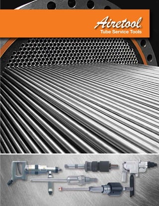
Airetool Products and Services
Airetool Tube Cleaners and Tube Expanders are used
to fabricate and maintain boilers, heat exchangers,
condensers and other tubular type equipment. Job
proven in a variety of industries, Airetool products
serve such facilities as petro chemical plants, oil
refineries, nuclear and non-nuclear power plants,
paper, sugar and metal mills, air-conditioning
servicing and maintenance plants.
Products described in this catalog are representative
of the complete Airetool Tube Cleaner and Tube
Expander product lines. If a need develops which
can not be satisfied by our standard products,
please contact your Airetool Distributor, or your Apex
Tool Group Sales and Service Center.
Apex Tool Group, LLC
5. 3
The Airetool® family of tube service
tools is one on the most diverse
in the heat transfer industry with a
broad selection of tube expanders,
tube rolling controls, tube cleaners,
and re-tubing tools to cover various
applications.
Tools that perform
Improving production rates and
decreasing cost are critical to the
success of today’s manufacturer or
contractor. The Airetool line of tools
are designed and manufactured to
perform consistently time after time.
When it comes to performance and
reliability, there is no doubt as to
why manufacturers and contractors
around the world have come to rely
on the Airetool brand of products.
Tools of the highest quality
When we say our tools are built well,
we really mean it. Apex Tool Group
manufacturing processes are ISO
9001 certified… that means the
Airetool brand is manufactured to the
highest standard.
Tools that work with
the operator
It is simple... give an operator a tool
that is comfortable to use and the
operator will work better. Airetool
tool balancing systems do just that,
coupled with extending expander or
other tooling life.
Airetool Overview
6. 4
Tools that set the standard
Outstanding performance, incredible durability,
plus the ease of maintenance have made Airetool
tube rolling controls the standard which all other
manufacturers are measured against.
Why use torque control when
expanding tubes?
Torque controlled tube rolling increases productivity
by achieving the desired tube wall reduction each
and every time a tube is expanded. Torque-controlled
tube rolling compensates for variations in the tube
wall thickness and the tube sheet hole dimensions.
What is tube wall reduction?
Tube wall reduction is the percent the tube wall
is reduced after the tube OD has contacted the
tube sheet ID. The amount of tube wall reduction
varies with the tube material, the tube sheet material
and the design requirements of the unit. Several
factors including pullout strength, tube and tube wall
thickness, tube sheet material and thickness, and
operating pressure are considered in determining the
optimum wall reduction.
Tube Rolling Set – Up Guide
Pick five tubes in the vessel to be rolled and
complete the work sheet below. It is important that
the measurements used in the set up are actual.
Never use averaged dimensions.
Always Use Engineering Design Specifications
for Tube Wall Reduction Percentage
Satisfactory joints are produced using the above
listed percentage of tube wall reduction.
• Step A – Measure tube sheet hole
• Step B – Measure tube OD
• Step C – Calculate clearance (A-B)
• Step D – Measure tube ID
• Step E – Calculate 2x wall thickness (B-D)
• Step F – Calculate 5% wall reduction* (.05 x E)
• Step G – Calculate finished rolled ID (C+D+F)
After the work sheet is finished, start setting up the
torque control motor by test rolling the first of the five
tubes. The first test roll must be done with the Airetrol
or Electric tube rolling motor set for low torque to
avoid over rolling.
Measure the tube ID after rolling the first tube. If more
expansion is needed, increase the torque setting
on the control and roll the second tube. Check the
finished ID. This step may require repeating on tube
three, but by the fifth tube you should have achieved
your desired finished rolled ID of step G below. The
tubes rolled to calibrate the tube wall reduction can
now be re-rolled at the correct setting.
Joint Number
STEP EXAMPLE 1 2 3 4 5
A Tube Sheet Hole .760"
B - Tube OD .750"
C = Clearance .010"
D Tube ID .620"
E 2 x Wall Thickness .130"
F +5% Wall Reduction* .006"
G = Finish Rolled ID .636"
*Example only
Rolling Controls
Introduction
7. 5
Airetrol Air Driven Rolling Motors
Airetool rolling motors control expansion by the
accurate measurement of torque. They automatically
stop expanding according to a predetermined
setting. Torque control prevents over- and under-
expansion of tubes, assures uniformly tightened tube
joints, and provides maximum holding strength for
individual tubes. All Airetrols include torque sensing
cams designed and manufactured specifically for
tube expanding applications.
model 720
model 850
model 1050
model 1550
Rolling Controls
Hand-held Torque Controller Rolling Motors
■ Strong, lightweight aluminum housings for easier
handling and less operator fatigue
■ Rugged drive combines precision control and
measured torque output
■ Simple dial-a-torque adjustment collar for easy set up
■ Cushioned shut-off reduces torque reaction
■ Quick change chucks to improve productivity
Model
Number
Order
Number
Speed Torque @ 90 psig Air Pressure*
Overall
Length
Weight
Side to
Center
Operating
Hose CFM
Square
Drive
Tube
Capacities*
Quick Change
Chuck (in.)Free
Speed
Max. Torque Min. Torque
RPM in. lbs. Nm in. lbs. Nm in. mm lbs. Kg in. mm in. mm in. in. mm Included Optional
720-2500B 8405541 2500 20.0 2.3 2.0 0.23 7.875 198 2.4 1.09 0.813 20.7 3/8 9.5 17 1/4 1/4 6.4 1/4 3/8
720-2500B 3/8 8405561 2500 20.0 2.3 2.0 0.23 7.875 198 2.4 1.09 0.813 20.7 3/8 9.5 17 1/4 1/4 6.4 1/4 3/8
720-1800B 8405383 1800 27.0 3.1 2.0 0.23 7.875 200 2.4 1.09 0.813 20.7 3/8 9.5 17 1/4 3/8 9.5 1/4 3/8
720-1800B 3/8 8405512 1800 27.0 3.1 2.0 0.23 7.875 200 2.4 1.09 0.813 20.7 3/8 9.5 17 1/4 3/8 9.5 1/4 3/8
720-550B 8405391 550 75.0 8.5 2.0 0.23 8.625 219 2.7 1.22 0.813 20.7 3/8 9.5 17 3/8 1/2 12.7 3/8 1/4
850-1250A 8405399 1100 115.0 13.0 22.0 2.49 12.250 311 10.5 4.76 1.438 36.5 1/2 12.7 48 3/8 3/4 19.1 3/8 1/2
850-600A 8405398 500 192.0 21.7 31.0 3.50 12.250 311 10.5 4.76 1.438 36.5 1/2 12.7 48 3/8 1 25.4 3/8, 1/2 -
*Varies depending on tube material, gauge, and tube sheet thickness
Model
Number
Order
Number
Speed Torque @ 90 psig Air Pressure*
Overall
Length
Weight
Side to
Center
Operating
Hose CFM
Square
Drive
Tube
Capacities*
Quick Change
Chuck (in.)Free
Speed
Max. Torque Min. Torque
RPM ft. lbs. Nm ft. lbs. Nm in. mm lbs. Kg in. mm in. mm in. in. mm Included Optional
1050-400 8404200 394 22.0 29.8 6.5 8.8 13.625 346 14 6.35 1.938 49.2 3/4 19.1 68 1/2 1-1/4 31.8 3/8, 1/2 3/4, 1
1050-400 HD 8404201 394 29.5 40.0 7.5 10.2 13.625 346 14 6.35 1.938 49.2 3/4 19.1 68 1/2 1-1/4 31.8 3/8, 1/2 3/4, 1
1550-900 8404290 756 30.7 41.6 4.7 6.4 18.000 457 27 12.25 1.938 49.2 3/4 19.1 70 1/2 1-1/2 38.1 3/8, 1/2 3/4, 1
1550-250 8404280 217 100.0 135.5 25.0 33.9 18.000 457 27 12.25 1.938 49.2 3/4 19.1 56 3/4 2-1/2 63.5 3/4, 1 3/8, 1/2
*Varies depending on tube material, gauge, and tube sheet thickness
8. 6
1850 Series Torque Control
Rolling Motors
Heavy duty torque controlled rolling motor capable of
rolling boiler tubes up to 4-1/2 O.D.
■ Offers the highest controlled torque of any
rolling motor currently available.
■ Torque range 320 - 570 ft.lbs.
1750 Series Right Angle Torque
Control Rolling Motors
These right angle torque control rolling motors are
used to roll tubes into drums of package and
stationary boilers.
■ Heavy duty gear train components for increased
durability
■ External torque control setting for easy
adjustment
■ Rotating exhaust deflector and indexing angle
head for operator control and comfort
■ Modular construction simplifies tool
maintenance
■ Roll Throttle makes for safe operation in any
working position
Model
Number
Order
Number
Speed Torque 90 psig Air Pressure*
Overall
Length
Weight
Side to
Center
Operating
Hose CFM
Square
Drive
Tube
Capacities*
Chucks
(in.)†Free
Speed
Maximum Torque Minimum Torque
RPM ft. lbs. Nm ft. lbs. Nm in. mm lbs. kg in. mm in. mm in. mm Incl. Opt.
1850 Series Torque Control Rolling Motors
1850-90 8405315 82 301 408 92 125 13 330 46 20.9 3.375 86 1/2 12.7 60 1 3-1/2 89 3/4, 1 1-1/4, 1-1/2
1850-40 8405314 34 570 772 320 434 15 381 52 23.6 3.625 92.1 1/2 12.7 60 1 4-1/2 114 3/4, 1 1-1/4, 1-1/2
*Varies depending on tube material, gauge, and tube sheet thickness
Model Number Order Number
Speed Torque 90 psig Air Pressure*
Overall
Length
Weight
Head Dimensions Square
Drive
Size
Tube
Capacities*
Chuck
Size
(in.)†
Free
Speed
Maximum Torque Minimum Torque
Side to
Center
Height Less Square
Drive
RPM ft. lbs. Nm ft. lbs. Nm in. mm lbs. kg in. mm in. mm in. in. mm incl.
1750 Series Reversible – Roll Throttle
1753-R-190 8405420 190 140 190 70 95 20.1 530.0 13.0 5.8 1.1 28.0 2.60 65.0 5/8 2.5 63.5 3/4
1753-RS-190 8405422 190 155 210 0 0 19.4 490.0 11.4 5.2 1.1 28.0 2.50 64.0 5/8 2.5 63.5 3/4
1752-R-90 8405421 90 305 413 150 203 21.7 550.0 14.8 6.7 1.5 37.0 2.75 70.0 3/4 4.0 101.5 3/4, 1
1752-RS-90 8405423 90 325 440 0 0 20.1 511.0 13.1 6.0 1.4 37.0 2.8 70.0 3/4 4.0 101.5 3/4, 1
1750 Series Reversible – Lever Throttle
1752-L-90 8405425 90 305 413 150 203 21.7 550.0 14.8 6.7 1.5 37.0 2.60 65.0 3/4 4.0 101.5 3/4, 1
† See page 13 for chuck size chart.
*Varies depending on tube material, gauge, and tube sheet thickness
Standard Equipment
Air Inlet: 1/2 NPT
Minimum hose size: 1/2
Splined torque reaction plate and reaction bar included (8567610)
model 1850-40
model 1752-R-90
Rolling Controls
Hand-held Torque Controller Rolling Motors
9. 7
Operation:
With the tube expander positioned inside the tube,
slight forward pressure on the Airetrol starts the
motor in forward direction to expand the tube. Once
the preset torque is met, the motor automatically
reverses and the tube expander can be removed
from the tube. The tube expander holder is spring
loaded, keeping the tube expander in the retracted
position to assist the expander entering the tube.
Model Number Order Number
Post Height Vertical Travel Horizontal Travel
in. mm in. mm in. mm
DAS 100 THB - Balancer Less Rolling Motor
DAS 100 THB 5526551PT 29.0 736.6 14.5 368.3 77.0 1955.8
Model Number Order Number
Free
Speed
Speed Torque 90 psig Air Pressure
CFM
Tube Capacities* Chucks (in.)†
Maximum Torque Minimum Torque
RPM in. lbs. Nm in. lbs. Nm in. mm Included Optional
DAS 100 TRS 720 Tube Rolling Systems with Motors
DAS 100 720 2500B 5525242 2500 20.0 2.26 2.0 0.23 17 1/4 6.3 1/4 3/8
DAS 100 720 1800B 5525243 1800 27.0 3.05 2.0 0.23 17 3/8 - 1/2 12.7 1/4 3/8
DAS 100 720 1800B 3/8 L** 5526141 1800 27.0 3.05 2.0 0.23 17 3/8 - 1/2 12.7 3/8 1/4
DAS 100 720 550B 5525244 550 75.0 8.48 2.0 0.23 17 1/2 - 5/8 15.8 3/8 1/4
DAS 100 720 550B L** 5526142 550 75.0 8.47 2.0 0.23 17 1/2 - 5/8 15.8 3/8 1/4
† See page 13 for chuck size chart.
*Varies depending on tube material, gauge, and tube sheet thickness
**L = Auto-lube
Rolling Controls
Bench-Top Mounted Tube Rolling Systems
DAS-100-TRS Tube Rolling System
Tube rolling system for bench
top tube rolling. The support
post can be mounted directly
on a work-bench or workstation
pedestal for easy access.
Suitable for tube rolling
applications of 1/4 thru 5/8 O.D.
tubes.
■ Absorbs torque reaction while supporting tool
weight for improved productivity and ergonomics
■ Aligns expander with tube sheet
for better repeatability
■ Push-to-start tube rolling cycle
■ Utilizes G-900, G-1300 and G-800 series
tube expanders
■ Auto-lube system configurations for use with
G-800 series expanders with lube collars
10. 8
Rolling Controls
DAS II Dominator Tube Rolling Systems
DAS II Dominator System
The Airetool DAS II Dominator Tube Rolling System
was designed to take pneumatic tube rolling
technology to the next level using time proven
Airetrol rolling motors outfitted with on-board
pneumatic control logic.
■ Fully pneumatic system for fabrication shops
and/or field service work
■ “Basic” unit works well with tube pulling, tube
end facing, and orbital welding equipment
■ Greatly enhances the accuracy of tube rolling
reducing costly rework of improperly rolled tubes
■ Increases expander life (up to 3X) compared to
conventional hand-held equipment
■ Ergonomic design supports tool weight and
torque reaction
■ Floor lock holds system in place for stability
while rolling tubes
■ Right or left hand operation without conversion
■ Five foot vertical and horizontal reach
■ Available in three different configurations: Basic
Unit*, Standard, Lubricator
Model Number
Order
Number
Movement
Lift Capacity Operating Pressure Operating Hose Allowable Torque
Vertical Horizontal
ft. m ft m lbs. kg PSI Bar in. mm ft.-lbs. Nm
Automatic Tube Rolling System Less DAS II Airetrol
DAS II Dominator 5526081 5.0 1.5 5.0 1.5 55 25 90 6.2 3/4 19.1 125 169
DAS II Dominator w/lube 5526140 5.0 1.5 5.0 1.5 55 25 90 6.2 3/4 19.1 125 169
Basic Positioning Unit*
DAS II Dominator Basic Unit 5529158 5.0 1.5 5.0 1.5 55 25 90 6.2 3/4 19.1 125 169
DAS II Dominators
DAS II Component Basic Unit* Standard With Lube
Base * * *
Tower * * *
Articulating ToolArm * * *
Filter Lubricator (Tool) * *
Airetool Supply Hoses * *
Lubricator (Expander) *
*The basic positioning unit can be used to support a wide variety of tube service tools
including drills, end facers, tube cutting tools, tube pulling rams, and tube cleaning motors
11. 9
Rolling Controls
DAS II Rolling Motors
DAS II Dominator System
The Airetool DAS II Dominator Rolling Motors are
designed to deliver power, performance, and
durability while providing accurate and repeatable
tube expansion.
■ Time proven torque control rolling motors with
on-board pneumatic control logic
■ Simple dial-a-torque adjustment collar for easy
set up
■ Push-to-start configurations (no suffix) run only
when activated, reducing noise and conserving
shop air
■ Timed Start* configurations (T suffix) cycle
continuously for trigger free tube rolling
■ Tool Options include “Cycle Counter” (C suffix)
and “Expander Lubricator (L suffix)
Examples: DAS II 1550 900 TCL is a timed start model
with counter lube
DAS II 850 1250 CL is a push-to-start model
with counter lube
*Timed Start option will run continuously when the toggle switch is
in the “on” position. After the tube is rolled and the tool switches
into reverse rotation, an adjustable delay timer is activated. The tool
will start running in the forward direction again after the time delay
is finished. (Available only on 1050 1550 Series.)
Model Number
Order
Number
Free Speed
CFM
Maximum Torque Minimum Torque Chucks (in.)†
RPM ft. lbs. Nm ft. lbs. Nm Included Optional
DAS II Dominator Rolling Motors*
DAS II 850 1250 Airetrol 8405562 1100 48 9.6 13.0 1.8 2.4 3/8 1/2
DAS II 850 1250 CL Airetrol 8405567 1100 48 9.6 13.0 1.8 2.4 3/8 1/2
DAS II 850 600 Airetrol 8405569 500 48 16.0 21.7 2.6 3.5 3/8, 1/2 -
DAS II 850 600 CL Airetrol 8405578 500 48 16.0 21.7 2.6 3.5 3/8, 1/2 -
DAS II 1050 400 TCL Airetrol 8405594 394 68 29.5 40.0 7.5 10.2 3/8, 1/2 3/4 - 1
DAS II 1550 900 Airetrol 8405563 756 75 30.7 41.6 4.7 6.4 3/8, 1/2 3/4, 1
DAS II 1550 900 CL Airetrol 8405565 756 75 30.7 41.6 4.7 6.4 3/8, 1/2 3/4, 1
DAS II 1550 900 T Airetrol 8405576 756 75 30.7 41.6 4.7 6.4 3/8, 1/2 3/4, 1
DAS II 1550 900 TCL Airetrol 8405580 756 75 30.7 41.6 4.7 6.4 3/8, 1/2 3/4, 1
DAS II 1550 250 Airetrol 8405564 217 75 100.0 135.5 25.0 33.9 3/4, 1 3/8, 1/2
DAS II 1550 250 T Airetrol 8405577 217 75 100.0 135.5 25.0 33.9 3/4, 1 3/8, 1/2
DAS II 1550 250 CL Airetrol 8405568 271 75 100.0 135.5 25.0 33.9 3/4, 1 3/8, 1/2
† 3/8 1/2 are QC Chucks (quick change)
* Configurations
No suffix - Basic Airetrol, push-to-start (PTS)
C suffix - PTS with Counter
L suffix - PTS with Lubricator
T suffix - Timer (continuous cycling, negates PTS, available only on 1050 1550 Series)
12. 10
Rolling Controls
Electronic Controller Electric Rolling Motors
model 979-c
model 999-c
Model
Number
Order
Number
Input Voltage
Current Requirements
Weight
Dimensions
Supply Adjustment Length Width Height
VAC Hz. Amps Amps lbs. kg in. mm in. mm in. mm
Electronic Controller
ATC 900* 2996326 120 50/60 20 0.1 7.2 3.27 11.75 298.5 12 304.8 7.63 193.8
*Not CE certified
Standard Equipment: Power Cord 2996733PT
Optional Equipment: Step down transformer (220VAC to 110VAC) 8405529
Electronic Controller
The ATC-900 Electronic Controller is a compact,
lightweight and durable microprocessor based
electronic motor controller. It is designed to provide
accurate torque control for Airetool electric rolling
motors by monitoring the amperage that the tool is
using and comparing it to a preset current limit value.
When the preset current limit value is reached, the
controller opens the circuit which stops the motor.
The current limit value is adjusted using the up/
down push-buttons on the front of the controller to
increment or decrement the current limit set point.
■ ATC-900 Controller automatically identifies
connected motor
■ GFCI Power Cord for operator safety
■ Expansion counter increments each time the
controller shuts off the tool
■ Up/down pushbuttons used to preset torque
shutoff set point in 0.1Amp increments
■ Auxiliary Receptacles for Trip Light
and Lubricator
Model
Number
Order
Number
RPM
Maximum
Torque
Minimum
Torque
Tube
Capacity*
Weight Chucks
ft. lbs. Nm ft. lbs. Nm in. mm lbs. kg in.
Electric Rolling Motors
979-C-210 8405489 210 40.0 54.2 20.0 19.0 3/4–2 19.1–50.8 32.0 14.5 3/8-1/2 QC
979-C-300 8405488 300 28.0 37.9 14.0 8.8 3/4–1-1/2 19.1–38.1 32.0 14.5 3/8-1/2 QC
979-C-650 8405487 650 13.0 17.6 6.5 128.7 5/8–1-1/4 15.9–31.8 32.0 14.5 3/8-1/2 QC
999-C-45 8405492 45 190.0 257.5 95.0 128.8 2–4 50.8–101.6 32.0 14.5 3/4-1
*May vary due to tube wall, material and/or tube sheet thickness.
Standard Equipment: Controller cable
Model Number
Order
Number
Length
ft. m
System Cables
ATC 900 Power Cord, GFCI 2996733PT 8.0 2.5
979 Motor to Controller 8405493 15.0 4.6
979 Motor to Wall Outlet 8405495 10.0 3.1
999 Motor to Controller 8405494 15.0 4.6
999 Motor to Wall Outlet 8405545 10.0 3.1
Model Number Order Number
Accessories
Universal 2KVA Step Down Transformer 220/110 VAC 8405529
Airetool Electric Rolling Motors
may be used without the ATC-900
Electronic Controller and plugged
directly into a wall outlet using a
“Optional” Direct Power Cord.
(see chart below)
Airetool Electric Rolling Motors may
be used with the DAS II Dominator
“Basic Unit” (see page 6) by using
a 8405583PT Mounting Kit.
13. 11
Rolling Controls
Electronic Controller Electric Rolling Motors
TEC 7000 Series Electronic Controller
TEC 7000 series electronic controller for use with hand-held rolling
motors and trolley type units (with telescopic shaft).
TEC 7000 General Specifications
■ CE Certified design
■ Microprocessor controlled tube expansion
■ Memory storage up to 3000 cycles
■ Operating language in English or German
■ Statistics for Quality Assurance include; Min / Max value for the
number of expansion cycles in memory can be shown on display
or send to the serial printer port
■ Programmable timers for; cycle start, reverse pause, end of
cycle, and a suppress timer for low torque value settings.
■ Programmable torque shut-off value and high / low torque limits
■ Three cycle modes - manual, semi-automatic, and full automatic
TEC 8000VS Series Electronic Controller
TEC 8000VS series electronic controller for use with trolley type units (with telescopic shaft)
TEC 8000VS General Specifications
■ CE Certified design
■ Standard 1-phase operation 230V supply, optional 120V supply
■ Universal controller for use with 3-phase motors or brushless
servomotors
■ Unique variable speed motor control
■ Programming functionality the same as TEC 7000
■ Custom solutions designed for TEC Controllers working with 3 ph - 42 Volt transformers used in
multi-spindle systems, applications with robot and/or articulating arm tool holder systems, and more.
Please contact your authorized Airetool distributor for details, system specifications, and recommendations.
Model Order Number Speed RPM
Tube Capacities OD*
Voltage
Power (Watt) Chucks (in.)
in. mm Input Output Standard Optional
Electric Rolling Motor Specifications
TEC 72636 941312 1 1400 1/4 - 3/8 6.35 - 9.52 230 300 180 1/4 QC
TEC 7113 941315 2 450-1550 5/8 - 1 1/4 15.88 - 31.75 110 650 450 3/8, 1/2 QC
TEC 7213 941313 2 450-1550 5/8 - 1 1/4 15.88 - 31.75 230 650 450 3/8, 1/2 QC
TEC 7132 941203 4
110-190
3/4 - 2 1/2 19.05 - 63.50 110 1500 980
MC 3 x 1/2 QC
350-590 MC 3 x 3/8 QC MC 3 x 1/2 SQ
TEC 7232 941202 4
110-190
3/4 - 2 1/2 19.05 - 63.50 230 1500 980
MC 3 x 3/8 QC MC 3 x 1/2 SQ
350-590 MC 3 x 3/4 SQ
* May vary due to tube wall, material and/or tube sheet thickness.
Model Number Order Number
Input Voltage (1 phase)
Power Requirements
(Watt)
Weight
Dimensions
Width Height Depth
VAC Hz. Input Output lbs. kg. in. mm in. mm in. mm
Electronic Controller
TEC 7000 941204 110-240 50/60 650 1700 25.7 11.7 13.4 340.0 6.7 170.0 16.5 420.0
Optional Equipment: TEC-9000 FS foot switch, order number 7940080
14. 12
Rolling Controls
Multi-Spindle Tube Rolling Systems
Fixture Mounted Tube Rolling
Systems—Electric Driven
Utilizing a microprocessor controlled expanding
cycle with programmable expansion parameters
including torque, speed, and time. This ensures a
very accurate, uniform, and repeatable process.
Expansion modules available for single or multiple
spindles (up to 16) with fixed or adjustable pitch
designs.
■ Fully programmable automatic expansion cycle
■ View and/or export tube expansion results for
data archive and QA analysis
■ Through-cage lubricant-injection system
increases the durability of the tooling
(expanders)
■ Robot or articulating arm mounting provides
for an ergonomic solution and effortless
productivity gains
Dual Spindle Torque Control Tube
Expansion Systems - Air Driven
Utilizing 720 series Airetool motors to achieve almost
twice the production rate of a hand-held rolling
motor. A “dual start” button activates both motors,
while left-start/right-start buttons are used for
independent single tube rolling.
■ Torque control tube rolling with
automatic reverse
■ Commonality of components
with other rolling motors
15. 13
Analyzer Adapter
Model P-15
Rolling Controls
Accesories
Model P-15 Torque Analyzer
Use the P-15 analyzer to set a specific torque value
on Airetrol rolling controls. The torque analyzers’
readings may be used as a standard for the Airetrols
performance providing greater quality control over
rolled tube joints.
■ Set rolling motor at a specific torque value
■ Enhances quality control with torque
value consistency
■ Time saver with multiple rolling
motor applications
Optional and Replacement Chucks
Chuck Description
Order
Number
Input
Square
Drive (in.)
Output
Mandrel
Square (in.)
720-720S-735S
720 250 1/4 Chuck 8405334 3/8 1/4
720 375 B 3/8 Chuck ASSY 8405403 3/8 3/8
850
850 375 QC chuck 8400100 3/8 3/8
850 500 QC chuck 8400200 3/8 1/2
1050-400 1550-900
1000 375 QC Chuck complete 8400700 1/2 3/8 QC
1000 500 QC Chuck complete 8400800 1/2 1/2 QC
1000 750 Chuck complete 8400900 1/2 3/4
1000 1000 Chuck complete 8404820 1/2 1
1550-250
QC 1550 500 QC Chuck complete 8405272 3/4 3/8 QC
QC 1550 500 QC Chuck complete 8405271 3/4 1/2 QC
1550 750 Chuck complete 8405259 3/4 3/4
1550 1000 Chuck complete 8405260 3/4 1
999/1850s
989 750 3/4 square chuck 8404700 1 3/4
989 1000 1 square chuck 8404960 1 1
1850 1250 chuck complete 8405319 1 1-1/4
1850 1500 chuck complete 8405437 1 1-1/2
1752
1770 110 3/4 chuck complete 8405299 3/4 3/4
1770 110 1 chuck complete 8405300 3/4 1
1770 110 1-1/4 chuck complete 8405400 3/4 1-1/4
1753
QC 1770 230 1/2 QC chuck complete 8405302 5/8 1/2
1770 230 3/4 chuck complete 8405298 5/8 3/4
1770 230 1 chuck complete 8405306 5/8 1
966s
850 375 chuck 8400100 3/8 3/8
979s
939 375 chuck 8400400 5/8 Hex 3/8
939 500 chuck 8400500 5/8 Hex 1/2
939 750 3/4 chuck 8401100 5/8 Hex 3/4
Model
Number
Order
Number
Graduations Capacity Accuracy
Height Width Length Weight
in. mm in. mm in. mm lb. kg
P-15 Torque Analyzer
P -15 810002PT 2 in.-lbs. 5 - 150 in. lbs. ± 1% +1/2 in.-lbs. 8.0 203.0 5.0 127.0 18.0 457.0 23.0 10.4
MP -15 (metric) 810151 5 cm-kg. 5 - 180 cm-kg ± 1% +1 cm-kg 8.0 203.0 5.0 127.0 18.0 457.0 23.0 10.4
General: Drive Size: 5/16” male hex Optional Equipment: Calibration Kit – 810080
Adapter
Number
Order
Number
Adapter Used with the
Following Expanders
Adapters for P-15 Analyzer
AD-1 8566501 1201 thru 1203 801 thru 803
AD-2 8566503 1205 805
AD-3 8566502 1207 thru 1210 807 thru 810
AD-4 8567012 1211 thru 1214 811 thru 814
AD-5 8566521 1215 thru 1220 815 thru 820
AD-6 8566518 1221 thru 1224 821 thru 824
AD-7 8566519 1225 thru 1230 825 thru 830
AD-8 8566514 1231 thru 1234 831 thru 834
AD-9 8566531 1235 thru 1240 835 thru 840
AD-8 8566475 1241 thru 1242 831 thru 842
AD-10 8566475 1243 thru 1248 843 thru 846
AD-11 8566520 1247 thru 1254 847 thru 854
AD-12 8566676 1255 thru 1260 855 thru 860
AD-13 8567332 1261 thru 1266 861 thru 866
AD-14 8566649 1267 thru 1272 867 thru 872
AD-15 8567039 1273 thru 1276 873 thru 878
AD-16 8567289 1279 thur 1288 870 thru 888
AD-17 8567050 1289 thru 1290 889 thru 890
AD-18 8567602 1291 thru1294 891 thru 894
AD-19 8567230 1295 thru 1300 895 thru 900
For information on AD-0 to AD-08 adapters for P2-B Analyzer, contact technical service.
16. 14
Heat Exchanger – Condenser Expanders
900 series
1/4 (6.3 mm) - 3/8 (9.5 mm) O.D.
1300 series
3/8 (9.5 mm) O.D.
8012 series
1 3/4 (44.4 mm) - 3 (76.2 mm) O.D.
800 series
1/2 (12.7 mm) - 1 1/2 (38.1 mm) O.D.
1200 series
1/2 (12.7 mm) - 1 1/2 (38.1 mm) O.D.
Mandrel, Rolls and Cage are the three things
common to all expanders. Other parts added further
classify the type of expander.
Thrust Assemby – This assembly attaches to the
cage and allows adjustment of the expanding depth.
The thrust collar will remain stationary against the
tube sheet or tube end while the cage, mandrel and
rolls expand the tube. A thrust assembly is used on
condenser/heat exchanger expanders, some furnace
expanders and special boiler expanders.
The world standard in
tube expanders
Airetool heat exchanger and
condenser expanders have
long been recognized as the
standard to which
all other brands
are measured. The
extra time spent manufacturing our
expanders results in consistent
performance and incredible
durability that OEM Heat Exchanger
Manufacturers expect.
Tube Expanders
Tube expanding is the art of
cold working the
ends of tubes
into intimate
contact with the metal of
the containing tube holes
to form a leak proof mechanical
seal and/or joint. In other words,
it is a mechanical method of
establishing a mechanical joint
between a tube and a tube hole.
Airetool manufactures condensed/
heat exchanger expanders, boiler
expanders, furnace expanders and
many special application expanders.
Tube expanders consist of:
Mandrel – A tapered pin through the center of the
expander to which the power is attached and when
advanced pushes the rolls against the tubes.
Rolls – A set of (3 or more) of tapered cylindrical parts
which are driven by mandrel and contact the tube wall
to be expanded. The taper on the rolls is in the reverse
direction and one-half the taper of the mandel if it is a
parallel roll expander.
Cage – This is the expander body (or housing) that
holds the mandrel and rolls in place. The slots which
contain the rolls also provide a feed angle which helps
pull the mandrel in to provide expansion of the rolls
17. 15
Condenser/Heat Exchanger Expanders
Airetool Condenser Heat Exchanger Expanders are self‑feeding, parallel rolling, ball bearing thrust expanders. They
are available in standard sizes for 1/4 O.D. through 3 O.D. for tube sheets up to 6-3/4 thick. Other sizes and
lengths are available upon request. We supply most of the air conditioning manufacturers with expanders up to
sixteen feet in length.
To select the correct tube expander, the following information is required:
■ Tube OD
■ Tube wall thickness or BWG
■ Tube sheet thickness
■ Tube material
■ Longer reach expanders are available upon request
■ Special Conditions, i.e. enhanced tubing, thick tube sheets, double tube sheet,
baffle sheets, tubes close to tube sheet channel or other tubes, protrusions,
welded tubes, and tube bends close to the tube sheet.
Double Tube Sheet Applications
In a double tube sheet application additional information is required. The thickness of the outer tube sheet (primary
tube sheet) and inner tube sheet (secondary tube sheet) and the distance between the two must be known. When
expanding the tube in the primary tube sheet the expanders collar is positioned as in the figure above with an 800
series tube expander. For the secondary tube sheet a 1200
series expander is required with “S type (double radius)
rolls. The “S type rolls are required to allow the expander to
have clearance on each side of the secondary tube sheet
as shown in the figure below. The purpose of using “S type
rolls on an inner tube sheet and setting the expander’s collar
this way is to reduce stresses in the tube due to thermal
expansion and contraction of the tube while it is in service.
Setting the tube expander’s collar on Primary Tube Sheets
It is very important to set the tube expander’s collar in the correct position inside the tube sheet. The expander’s
roll high point should be positioned ~1/8 (3mm) from the inner side of the tube sheet as shown in the figure below.
The purpose for setting the expander’s collar this way is to allow for
thermal expansion and contraction of the tube while it is in service. If
the tube is expanded beyond the tube sheet, thermal expansion and
contraction of the tube will cause stress on the tube, which may cause
the tube to crack or rupture at the inner tube sheet location. When
tightening the set screw on the expander’s collar, be sure it is aligned
with the cage grove.
Example Only
Example Only
18. 16
Care and Maintenance of Tube Expanders
Tube expanders are precision tools and should be treated as such. The service demanded of them is severe.
Therefore, they must be given a reasonable amount of care to insure satisfactory operation and long life.
All Tube Rolling Applications
1. Before using, clean the expander thoroughly to remove any dirt or foreign matter.
2. Check thrust bearing and grease if needed. This should be done daily.
3. Proper lubrication of the expander during the rolling operation is a must in order to keep the rolls and mandrel
cool, to extend their life, and to insure uniform tube to tube sheet joints.
4. Inspect rolls and mandrels for scarring or chips regularly and if found, replace them immediately. One small chip
in a roll can cause the complete set of rolls and the mandrel to be damaged in a single rolling cycle. Always
replace rolls and mandrels at the same time.
5. When the rolling job is complete, wash the expander thoroughly and then oil and grease generously to prevent
rusting during storage.
Lubrication Cleaning
Hand-Held Rolling Applications
Depending on the severity of the rolling application, the expander should be washed periodically (every 25-100 tubes) in any
commercial solvent. For best expander life, the expander should be left in solvent to cool while a second expander is used to
continue rolling.
DAS Automated Tube Rolling Applications
An optional automatic lubrication system is offered for the automatic tube rolling systems. Hand cleaning is virtually eliminated
with the use of the automatic lubricating system as the air pressure that blows the lubrication into the expander to cool it also
blows away dirt or foreign matter during each cycle.
Heat Exchanger – Condenser Expanders
Step Rolling
Step rolling is required when expanding tubes in thick tube sheets. Typically the first expansion is made at the
innermost location, away from the inner side of the tube sheet. This is extremely
important when rolling the opposite end of the vessel. This allows the tube
material to grow in the proper direction towards the operator and keeps the tube
from being stressed. After all the tubes have been expanded in this location,
adjust the expander’s collar to overlap the previously rolled area. Repeat as
necessary until the complete thickness of the tube sheet has been expanded. “S
type rolls (double radius) are recommended for step rolling to provide a smooth
transition on the I.D. of the tube.
Five roll expander vs. Three roll expander
Many manufacturers prefer the five-roll expander for applications using tube materials that work harden quickly
such as stainless steel and titanium. The five-roll expander inherently has more contact area with the tube than
the three‑roll which reduces the amount of work hardening and spring back effect that is common with these tube
materials. They are also used in applications with closely spaced tubes having triangular pitch. The thinner the tube
walls, 18 BWG (.049/1.25mm) and thinner, the more apt work hardening is to occur.
19. 17
Tube Expander Lubricant “LUBE-A-TUBE
■ A water soluble lubricant especially compounded for
use with tube expanders. It prevents rust and acts as a
coolant providing longer life and smoother rolling.
■ 5-gallon container: LAT-5 (order number 2981695)
Flip Collars
All G-800 and G-1200 Series tube expanders are supplied
with a flip collar with a 10-32 UNF auto-lube port. The flip
collar allows for flush and recessed tube rolling. The standard
expander is supplied with a recess of 1/8 (3 mm). Other recess
lengths are available. Contact technical service for details.
Fixed Recess Thrust Collars
Fixed recess collars are available for tube projections between
3/16 (4.7mm) to 7/8 (22.2 mm) from the tube sheet for special
applications and require a quote from technical service.
Full Recess Thrust Collars
The full recess collar accommodates tube projections up to
7/8 (22.2 mm) from the tube sheet.
Adjustable Recess Thrust Collars
The adjustable recess collar accommodates tube projections
up to 1/2 (12.7 mm) from the tube sheet.
Thin Wall Thrust Collars
Thin wall thrust collars are recommended when expanding
20 BWG .035 (0.9 mm) or lighter wall tubes. This design
limits the possibility of the tube being drawn up inside the
thrust collar. Removing the collar’s collet allows the expander
to be used as a full recess style compensating for various
length tube projections from the tube sheet. These collars are
application specific and require a quote from technical service.
Small Diameter Thrust Collars
Small diameter thrust collars are recommended
for rolling tubes in confined areas, close to
tube sheet channels, or if there is interference
from adjacent tubes.
Tube Expander
Tube
Tube Sheet
Tube Sheet Channel
Thrust Collar
20. 18
“AN” Series Expanders
Selection Guide AN Series Heat Exchanger Condenser Tube Expanders
Tube O.D. Tube Gauge Tube I.D.
Tube Sheet Thickness
Min. I.D.
Tool Enters
Max. Expan.
of Tool Mandrel No.
(Order No.)
Square Drive
1/4 in. (6.3 mm)
Beariing No.
(Order No.)
Recommended
Rolling Motor
(Order No.)
1/4 in. to 1 in.
(6.3 mm to 25.4 mm)
in. mm BWG in. mm in. mm
Tool No.
(Order No.)
Roll Set No.
(Order No.)
in. mm in. mm
1/4 6.3
18 .049 1.24 .152 3.86
A-25018
(5515689)
R-20018
(5515705)
.148 3.76 .167 4.24
M-21819
(2980037)
NTA-613-A
(5515716)
720-2500B
(8405541)
19 .042 1.06 .166 4.21
A-25019
(5515653PT)
R-21920
(5515706)
.160 4.06 .180 4.57
20 .035 0.88 .180 4.57
A-25020
(5515654)
R-21920
(5515706)
.175 4.44 .196 4.97
M-22021
(2980038)
21 .032 0.81 .186 4.72
A-25021
(5515690)
R-22124
(5515707)
.180 4.57 .202 5.13
22 .028 0.71 .194 4.92
A-25022
(5515691)
R-22124
(5515707)
.190 4.82 .213 5.41
M-220022
(2980158)
23 .025 0.63 .200 5.08
A-25023
(5515692)
R-21920
(5515706)
.195 4.95 .216 5.48
M-22324
(2980149)
24 .022 0.55 .206 5.23
A-25024
(5515693)
R-22124
(5515707)
.201 5.10 .224 5.69
28 .014 0.35 .222 5.63
A-25028
(5515694)
R-22830
(5515709) .217 5.51 .243 6.17
M-22830
(2980150)29 .013 0.33 .224 5.68
30 .012 0.30 .226 5.74
3/8 9.5
14 .083 2.10 .209 5.30
A-37514
(5515695)
R-21920
(5515706)
.204 5.18 .230 5.84
M-22830
(2980150)
NTA-613-A
(5515716)
720-2500B
(8405541)
15 .072 1.82 .231 5.86
A-37515
(5515696) R-31516
(5515711)
.225 5.71 .265 6.73
16 .065 1.65 .245 6.22
A-37516
(5515697)
.238 6.04 .278 7.06
M-31617
(2980151)
17 .058 1.47 .259 6.57
A-37517
(5515698)
R-31720
(5515712)
.253 6.42 .293 7.44
18 .049 1.24 .277 7.03
A-37518
(5515699)
.270 6.85 .310 7.87
M-30018
(2980155)
19 .042 1.06 .291 7.39
A-37519
(5515700)
.285 7.24 .325 8.25
M-30019
(2980156)
20 .035 0.88 .305 7.74
A-37520
(5515701)
.295 7.49 .335 8.51
M-32021
(2980157)
21 .032 0.81 .311 7.90
A-37521
(5515702) R-32122
(5515713)
.305 7.74 .345 8.76
22 .028 0.71 .319 8.10
A-37522
(5515703)
.312 7.92 .353 8.96
M-32224
(2980159)
23 .025 0.63 .325 8.25
A-37523
(5515704)
R-32324
(5515715)
.318 8.07 .363 9.22
24 .022 0.55 .331 8.40
AN Series Expanders
O.D. Range:
1/4 – 3/8 Inches
6.3 – 9.5 mm
■ “AN” expanders have 1 (25.4mm) long rolls and will accommodate tube sheet
thicknesses from 1/4 to 1 (6.3 to 25.4mm).
■ Captive mandrel retained on the rear of the cage instead of an acorn nut on the tip of
the mandrel.
■ Heavy duty mandrel for improved durability.
21. 19
G-900 Series Expanders
O.D. Range:
1/4 – 3/8 Inches
6.3 – 9.5 mm
■ Expander with 3/4 in. (19.0 mm) long rolls will accommodate tube sheet thicknesses
from 1/4 in. to 3/4 in. (6.3 mm to 19.0 mm)
■ Expander with 1-1/4 in. (31.7 mm) long rolls will accommodate tube sheet thicknesses
from 3/4 in. to 1-1/4 in. (19.0 mm to 31.7 mm)
NOTE: Information on any size of tube not listed will be furnished upon request.
Condenser Expanders
Selection Guide G-900 Series Heat Exchanger Condenser Tube Expanders
Tube O.D. Tube Gauge Tube I.D.
Tube Sheet Thickness
Min. I.D.
Tool Enters
Max. Expan.
of Tool Mandrel No.
(Order No.)
1/4 in. Sq. Dr.
6.3 mm
Recommended
Controlled
Rolling Motors
Airetrol
(Order No.)
1/4 in. to 3/4 in.
(6.3 mm to 19.0 mm)
3/4 in. to 1-1/4 in.
(19.0 mm to 31.7 mm)
in. mm bwg in. mm in. mm
Tool No.
(Order No.)
Roll Set No.
(Order No.)
Tool No.
(Order No.)
Roll Set No.
(Order No.)
in. mm in. mm
1/4 6.3
18 .049 1.24 .152 3.86
921
(5016710)
921
(5175610
920
(5016700)
904
(5174800)
.151 3.83 .173 4.39
(921) M-39 (2520300)
(920) M-38 (2520100)
720-2500B
(8405541)
19 .042 1.06 .166 4.21
922
(5016800)
923
(5175700)
.165 4.19 .185 4.70
M-39
(2520300)
20 .035 0.88 .180 4.57
923
(5016901)
923
(5175700)
.175 4.44 .200 5.08
M-40
(2520500)
21 .032 0.81 .186 4.72
924
(5017000)
924
(5175800)
.180 4.57 .207 5.25
22 .028 0.71 .194 4.92
925
(5017100)
925
(5175900)
.190 4.82 .216 5.48
M-41
(2520700)
23 .025 0.63 .200 5.08
926
(5017200)
923
(5175700)
.195 4.95 .222 5.63
24 .022 0.55 .206 5.23
927
(5017300)
924
(5175800)
.201 5.10 .230 5.84
28 .014 0.35 .222 5.63
928
(5017400)
903
(5174700)
.222 5.63 .238 6.04
928
(2161300)
29 .013 0.33 .224 5.68 .222 5.63 .238 6.04
30 .012 0.30 .226 5.74
929
(5519723)
929
(5519757)
.205 5.21 .235 5.99
M-40
(2520500)
3/8 9.5
14 .083 2.10 .209 5.30
927
(5017300)
924
(5175800)
.201 5.10 .232 5.89
M-41
(2520700)
720-2500B
(8405541)
15 .072 1.82 .231 5.86
915
(5016410)
903
(5174700)
.230 5.84 .265 6.73
M-42
(2520900)
16 .065 1.65 .245 6.22
916*
(5016500)
916
(5175600)
.240 6.09 .275 6.98
M-36
(2519700)
16 .065 1.65 .245 6.22
916L*
(5512156)
916L
(5512157)
.240 6.09 .275 6.98
M-36L
(2968803)
17 .058 1.47 .259 6.57
918
(5016600)
903
(5174700)
920
(5016700)
904
(5174800)
.255 6.47 .289 7.34
M-38
(2520100)
18 .049 1.24 .277 7.03
901
(5015200)
903
(5174700)
902
(5015300)
.272 6.90 .307 7.79
M-30
(2518400)
19 .042 1.06 .291 7.39
903
(5015400)
903
(5174700)
904
(5015500)
.286 7.26 .330 8.38
M-31
(2518700)
20 .035 0.88 .305 7.74
905
(5015600)
907
(5174900)
906
(5015700) 908
(5175000)
.300 7.62 .334 8.48
M-32
(2518900)
21 .032 0.81 .311 7.90 907
(5015800)
907
(5174900)
908
(5015900)
.306 7.77 .340 8.63
M-33
(2519100)
22 .028 0.71 .319 8.10
909
(5016000)
909
(5175100)
910
(5016100)
910
(5175200)
.314 7.97 .349 8.86
M-34
(2519300)
23 .025 0.63 .325 8.25
911
(5016200)
911
(5175300)
912
(5016300) 912
(5175400)
.320 8.12 .357 9.06
24 .022 0.55 .331 8.40
911
(5016200)
911
(5175300)
912
(5016300)
.320 8.12 .357 9.06
* This expander has 1 long rolls.
22. 20
G-1300 Series Expanders
O.D. Range:
3/8 Inches
9.5 mm
■ Expanders with 3/4 in. (19.0 mm) long rolls will accommodate tube sheet thicknesses
of 3/4 in. to 3 in.(19 mm to 76.2 mm)
■ Expanders with 1-1/4 in. (31.7 mm) long rolls will accommodate tube sheet thicknesses
from 1-1/4 in. to 3-1/2 in. (31.7 mm to 88.9 mm)
NOTE: Information on any size of tube not listed will be furnished upon request.
Condenser Expanders
Selection Guide G-1300 Series Heat Exchanger Condenser Tube Expanders
Tube O.D. Tube Gauge Tube I.D.
Tube Sheet Thickness
Min. I.D.
Tool Enters
Max. Expan.
of Tool Mandrel No.
(Order No.)
1/4 in. Sq. Dr.
6.3 mm
Recommended
Rolling Motors
(Order No.)
3/4 in. to 3 in.
(19.0 mm to 76.0 mm) *
1-1/4 in. to 3-1/2 in.
(31.7 mm to 88.9 mm) *
in. mm bwg in. mm in. mm
Tool No.
(Order No.)
Roll Set No.
(Order No.)
Tool No.
(Order No.)
Roll Set No.
(Order No.)
in. mm in. mm
3/8 9.5
15 .072 1.82 .231 5.86
1315
(5512183)
1315
(5512184)
1316
(5512185)
1316
(5512180)
.230 5.84 .265 6.73
M-86
(2541400)
720-2500B
(8405541)
16 .065 1.65 .245 6.22
1319
(5512187)
903
(5174700)
1319-L
(5512190)
916-L
(5512157)
.240 6.09 .275 6.98
17 .058 1.47 .259 6.57
1317
(5512191)
1318
(5512192-5)
904
(5174800)
.255 6.47 .289 7.34
M-88
(2541600)
18 .049 1.24 .277 7.03
1301
(5055100)
1302
(5055200)
.272 6.90 .307 7.79
M-80
(2540000)
19 .042 1.06 .291 7.39
1303
(5055300)
1304
(5055400)
.286 7.26 .320 8.12
M-81
(2540200)
20 .035 0.88 .305 7.74
1305
(5055500) 907
(5174900)
1306
(5055600) 908
(5175000)
.300 7.62 .334 8.48
M-82
(2540400)
21 .032 0.81 .311 7.90
1307
(5055700)
1308
(5055800)
.306 7.77 .340 8.63
M-83
(2540600)
22 .028 0.71 .319 8.10
1309
(5055900)
909
(5175100)
1310
(5056000)
910
(5175200)
.314 7.97 .349 8.86
M-84
(2540800)
23 .025 0.63 .325 8.25
1311
(5056100)
911
(5175300)
1312
(5056200)
912
(5175400)
.320 8.12 .357 9.06
24 .022 0.55 .331 8.40 .320 8.12 .357 9.06
* NOTE: Step expanding becomes necessary if the tube sheet thickness exceeds the length of the roll.
23. 21
G-800 Series – 3-Roll Expanders
O.D. Range:
1/2 – 1-1/2 Inches
12.7 – 38.1 mm
■ Expanders with 1-1/2 in. (38.1 mm) long rolls will accommodate tube sheet thicknesses of
1/2 in. to 1-1/2 in. (12.7 mm to 38.1 mm)
■ Expanders with 2-1/4 in. (57.1mm) long rolls will accommodate tube sheet thicknesses
from 1-1/4 in. to 2-1/4 in. (31.7 mm to 57.1 mm)
■ Reversible Thrust Collar design allows flush and 1/8 in. recess tube rolling. Collars have
lubrication port for use with auto-lube configured ATR and DAS tube rolling systems.
Sizes not listed available upon request.
Condenser Expanders
Selection Guide G-800 Series Heat Exchanger Condenser Tube Expanders
Tube O.D. Tube Gauge Tube I.D.
Tube Sheet Thickness
Min. I.D.
Tool Enters
Max. Expan.
of Tool
Mandrel
Number
(Order No.)
3/8 in. Sq. Dr.
(9.5 mm)
Recommended
Rolling Motors
(Order No.)
1/2 in. to 1-1/2 in.
(12.7 mm to 38.1 mm)
1-1/4 in. to 2-1/4 in.
(31.7 mm to 57.1 mm)
in. mm bwg in. mm in. mm
Tool No.
(Order No.)
Roll Set No.
(Order No.)
Tool No.
(Order No.)
Roll Set No.
(Order No.)
in. mm in. mm Airetrol Electric
1/2 12.7
14 .083 2.10 .334 8.48
797
(5005780)
797
(5512194)
.324 8.22 .374 9.49
797
(2131300) 720-550-B
(8405391)
15 .072 1.82 .356 9.04
799
(5005782) R-1
(5284800)
.348 8.83 .398 10.10
799
(2131900)
16 .065 1.65 .370 9.39
801
(5005800)
.360 9.14 .410 10.41
M-1
(2511800)
720-1800-B-3/8
(8405512)
17 .058 1.47 .384 9.75
803
(5005900)
R-2
(5285000)
.374 9.49 .424 10.76
18 .049 1.24 .402 10.21
805 1/2
(5006000)
R-3
(5285200)
.392 9.95 .447 11.35
M-2
(2512100)
20 .035 0.88 .430 10.92
807 1/2
(5525444)
R-4
(5285400)
.420 10.66 .480 12.19
M-3
(2512400)
5/8 15.8
12 .109 2.76 .407 10.33
805 5/8
(5006001)
R-3
(5285200) .392 9.95 .447 11.35
M-2
(2512100)
850-600-A
(8405398)
13 .095 2.41 .435 11.04
807 5/8
(5006100)
R-4
(5285400)
.420 10.66 .480 12.19
M-3
(2512400)
14 .083 2.10 .459 11.65
809
(5006200)
R-4
(5285400)
810
(5006300)
R-4-A
(5285500)
.449 11.40 .509 12.92
M-4
(2512700)
15 .072 1.82 .481 12.21
811 5/8
(5006400)
R-5
(5285800)
812 5/8
(5006500)
R-5-A
(5285900)
.471 11.96 .536 13.61
M-5
(2513000)
16 .065 1.65 .495 12.57
813
(5006600) R-6
(5286200)
814
(5006700) R-6-A
(5286300)
.485 12.31 .550 13.97
850-1250-A
(8405399)
17 .058 1.47 .509 12.92
815 5/8
(5006800)
816 5/8
(5006900)
.499 12.67 .564 14.32
M-6
(2513300)
18 .049 1.24 .527 13.38
817 5/8
(5007000)
R-7
(5286600)
818 5/8
(5007100)
R-7-A
(5286700)
.517 13.13 .582 14.78
19 .042 1.06 .541 13.74
819
(5007200)
R-7
(5286600)
820
(5007300)
R-7-A
(5286700)
.531 13.48 .596 15.13
M-8
(2513900)
20 .035 0.88 .555 14.09
21 .032 0.81 .561 14.24
22 .028 0.71 .569 14.45