SOR Temperature Sensor Catalog
•
1 like•921 views

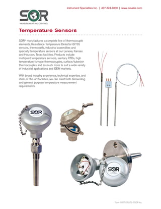
SOR manufactures a complete line of thermocouple elements, Resistance Temperature Detector (RTD) sensors, thermowells, industrial assemblies and specialty temperature sensors.

Recommended
Recommended
More Related Content
What's hot
What's hot (18)
Similar to SOR Temperature Sensor Catalog
Similar to SOR Temperature Sensor Catalog (20)
More from Instrument Specialties, Inc.
More from Instrument Specialties, Inc. (20)
Recently uploaded
Recently uploaded (20)
SOR Temperature Sensor Catalog
- 1. SORInc.com | 913-888-2630 | 1/36Form 1667 (05.17) ©SOR Inc. Temperature Sensors SOR® manufactures a complete line of thermocouple elements, Resistance Temperature Detector (RTD) sensors, thermowells, industrial assemblies and specialty temperature sensors at our Lenexa, Kansas and Houston, Texas facilities. Products include multipoint temperature sensors, sanitary RTDs, high temperature furnace thermocouples, surface/tubeskin thermocouples and so much more to suit a wide variety of industrial applications and OEM markets. With broad industry experience, technical expertise, and state-of-the-art facilities, we can meet both demanding and general purpose temperature measurement requirements. Form 1667 (05.17) ©SOR Inc. Instrument Specialties Inc. | 407-324-7800 | www.isisales.com
- 2. | 913-888-2630 | SORInc.com2/36 Form 1667 (05.17) ©SOR Inc. Table of Contents Design and specifications are subject to change without notice. RTDs (Resistance Temperature Detectors) Industrial Style with Spring. . . . . . . . . . . . . . . . . . . . . . . . . . . . . . . . . . . . . . . . . . . . . . . . . . . 3 Type 1150 with Plug. . . . . . . . . . . . . . . . . . . . . . . . . . . . . . . . . . . . . . . . . . . . . . . . . . . . . . . . . 4 Type 1250 with Leads. . . . . . . . . . . . . . . . . . . . . . . . . . . . . . . . . . . . . . . . . . . . . . . . . . . . . . . 5 Field Adjustable - cut to length. . . . . . . . . . . . . . . . . . . . . . . . . . . . . . . . . . . . . . . . . . . . . . . 6 Thermocouples Industrial Style with Spring . . . . . . . . . . . . . . . . . . . . . . . . . . . . . . . . . . . . . . . . . . . . . . . . . . . 7 Type 1100 with Plug. . . . . . . . . . . . . . . . . . . . . . . . . . . . . . . . . . . . . . . . . . . . . . . . . . . . . . . . . 8 Type 1200 with Leads. . . . . . . . . . . . . . . . . . . . . . . . . . . . . . . . . . . . . . . . . . . . . . . . . . . . . . . 9 Field Adjustable - cut to length. . . . . . . . . . . . . . . . . . . . . . . . . . . . . . . . . . . . . . . . . . . . . . . 6 Remote Mounted - Type 1340. . . . . . . . . . . . . . . . . . . . . . . . . . . . . . . . . . . . . . . . . . . . . . . 10 General Purpose -1400 Series with NPT process/instrument connections. . . . . . . 11 Temperature Assemblies with Thermowells. . . . . . . . . . . . . . . . . . . . . . . . . . . . . . . . . . . 12 Threaded and Flanged Thermowell Options. . . . . . . . . . . . . . . . . . . . . . . . . . . . . . 13 Socket, Weld In, Van Stone and Sanitary Thermowell Options. . . . . . . . . . . . . 14 Pipe Well Assemblies. . . . . . . . . . . . . . . . . . . . . . . . . . . . . . . . . . . . . . . . . . . . . . . . . . . . . . . 15 Pipe, Flanged and Threaded Thermowell Options . . . . . . . . . . . . . . . . . . . . . . . . 16 High Temperature with Unprotected Thermocouple and Protection Tubes. . . . . . . . . 17 Options and Accessories Connection Heads. . . . . . . . . . . . . . . . . . . . . . . . . . . . . . . . . . . . . . . . . . . . . . . . . . . . . 18 Terminal Blocks and Extensions. . . . . . . . . . . . . . . . . . . . . . . . . . . . . . . . . . . . . . . . . 20 Sensor Connectors & Accessories. . . . . . . . . . . . . . . . . . . . . . . . . . . . . . . . . . . . . . 21 Thermocouple Extension Wire. . . . . . . . . . . . . . . . . . . . . . . . . . . . . . . . . . . . . . . . . . 23 Sensor, Thermowell and Transmitter Options. . . . . . . . . . . . . . . . . . . . . . . . . . . . . 24 In-Head Temperature Transmitters. . . . . . . . . . . . . . . . . . . . . . . . . . . . . . . . . . . . . . 26 In-Head Displays. . . . . . . . . . . . . . . . . . . . . . . . . . . . . . . . . . . . . . . . . . . . . . . . . . . . . . 28 Bimetal Thermometers. . . . . . . . . . . . . . . . . . . . . . . . . . . . . . . . . . . . . . . . . . . . . . . . . . . . . . 29 Surface Electric Trace - Type 1500 & 1500R. . . . . . . . . . . . . . . . . . . . . . . . . . . . . . . . . . . 30 Pipe Clamp - Type 1550. . . . . . . . . . . . . . . . . . . . . . . . . . . . . . . . . . . . . . . . . . . . . . . 31 Washer Thermocouple - Type 1310. . . . . . . . . . . . . . . . . . . . . . . . . . . . . . . . . . . . . 31 Tubeskin Thermocouple - Type 1510 & 1520. . . . . . . . . . . . . . . . . . . . . . . . . . . . 32 Oil Seal - Type 1312 & 1314. . . . . . . . . . . . . . . . . . . . . . . . . . . . . . . . . . . . . . . . . . . 33 Heavy Duty Industrial Magnet - Type 1280 & 1290. . . . . . . . . . . . . . . . . . . . . . . . . . . 34 Multipoint - Type 2020, 2030 & 2040. . . . . . . . . . . . . . . . . . . . . . . . . . . . . . . . . . . . . . . 35 Temperature Elements Only Assemblies RTDs and Thermocouples with heads, wells transmitters and other options. Specialty Sensors Instrument Specialties Inc. | 407-324-7800 | www.isisales.com
- 3. SORInc.com | 913-888-2630 | 3/36Form 1667 (05.17) ©SOR Inc. Industrial Style with Spring - RTDsTemperature Sensors PO PH PM RN 1700 18 = 1/8” (3.2 mm) 316 = 3/16” (4.8 mm) 14 = 1/4” (6.4 mm) 38 = 3/8” (9.5 mm) 14 = 1/4” only (6.4mm) S = Single D = Dual TW = 2 Wire FW = 4 Wire GA = Class A HV = High Vibration (PM) CR = Cryogenic (PM) (Inches) Type OD Elements Length1 Material Options R = 316SS To order indicate a code/value for each component. Leave blank for standard. All RTDs are 100% tested to insure that the accuracy and the continuity of the product have not been affected by the manufacturing process. The standard sheath material on all RTDs specified in this section is 316SS. Other sheath materials and coatings are available. Specify using model 1150 on page 4. Elements are either thin film or wire wound, depending on the style RTD selected. Thin film elements are used in all constructions unless otherwise specified. Each RTD is supplied with a heavy duty spring. Notes 1 Length is determined by assembly when used in well or protection tube. To determine the length for replacement RTD’s use the following formula: U Length of well + T Length + A Length + 0.50” = Sensor Length See pages 12-16 for description of U, T & A lengths depending on type of well. Standard RTD Specifications Element Material: Platinum Element Type: 100 ohms @ 0°C, 0.00385 DIN Curve RTD Type: Three wire (Color code: red, red, white) Wire Gauge: 22 Gauge Three Wire (Standard) Design type Codes PO This design uses nickel clad copper lead wire insulated with Teflon® . Maximum upper temperature rating of 500°F (260°C). PH Our high temperature version can be used up to 900°F (482°C), and uses fiberglass leads. PM Heavy duty applications is where this style should be specified. It is suited for temperatures up to 900°F (482°C). Mineral insulated cable is used for this type of RTD. Can be used in cryogenic applications at temperatures down to minus 200°F (-129Cº). RN 120 Ohm nickel @ 0°C (Edison #7) Color code: red, red, black. (DIN 43760) 1700 Higher accuracy (available in 1/4” Single 4 wire & Dual 4 wire only). Maximum temperature rating of 302°F (150°C). Design Types The design types provide environmental and accuracy solutions to virtually any process RTD application. Accuracy options offer the user more choices for tighter process control. Class B accuracy has long been the work horse of the industrial RTD temperature loop and is a good fit for most process needs. Slightly better than Class B is Class A accuracy which has long filled the void for the most demanding accuracy needs. The 1700 Smart Sensors have surpassed the Class A specifications for those applications where process accuracy must be measured in hundredth’s of a degree. Optional NIST certification for 1700 products can be supplied and the accuracy statement is the finished product profile not just the accuracy of the element. The stability and accuracy of this product may eliminate costly and cumbersome sensor matching. Accuracy tolerances for platinum resistance elements are defined by DIN EN 60751(ITS 90) as follows: Class B: ∆t=± (0.3 + 0.005 l t l) Class A: ∆t=± (0.15 + 0.002 l t l) 1700: ∆t=± 0.1(0.3 + 0.005 l t l) Sensor Length 6.00” (15.24cm) Sensor OD Sensor Epoxy Seal Max. Temp. 300°F (149ºC) std. Four WireWire Configurations Class Temperature Range ºC ºF Class B -70° to +500° -94° to +932° Class A -50° to +300° -58° to +572° 1700 0° to +150° +32° to +302° Instrument Specialties Inc. | 407-324-7800 | www.isisales.com
- 4. | 913-888-2630 | SORInc.com4/36 Form 1667 (05.17) ©SOR Inc. Type 1150 with Plug - RTDsTemperature Sensors See page 24 for complete option descriptions. options FW Four-Wire (without connector) GA Class A HV High Vibration (M Construction) LB Connector “L” Bracket SS18 Adj SS Comp Fitting 1/8” NPT* SS14 Adj SS Comp Fitting 1/4” NPT* SS12 Adj SS Comp Fitting 1/2” NPT* TF Teflon® Coated Sheath VH Vent Hole in Compression Fitting *Add T after SS or BR for Teflon® Ferrule BA Bayonet Adapter (Adjustable) 1/8” (3.2 mm) OD only BF Bayonet Cap & Spring, 1/8” (3.2 mm) and 3/16” (4.8 mm) OD only Note: inches from cap to tip (fixed) BD45 45° Bend in Sheath Note: inches from bend to tip BD90 90° Bend in Sheath Note: inches from bend to tip BR18 Adj Brass Comp Fitting 1/8” NPT* BR14 Adj Brass Comp Fitting 1/4” NPT* BR12 Adj Brass Comp Fitting 1/2” NPT* CR Cryogenic (M Construction) CV Connector with Epoxy Sealed Screws Sensor OD Sheath Length W R R Termination 14 Mini Three Pin Plug 15 Mini Three Pin Jack 13 Large Three Pin Jack 12 Large Three Pin Plug 11 Spade Lugs 1 Bare Ends - 1” (2.54 cm) std. For longer leads, see Type 1250 (inches) Sensor Type RTD Type OD Construction Sheath Sheath Length Material SENSOR TYPE TERMINATION OPTIONS 1150 R RTD Type RP 100 ohm Platinum Temperature Coefficient .00385 ohms/ohm/°C RN 120 ohm Nickel (Edison #7) Temperature Coefficient 0.00672 ohms/ohm/°C Other temperature coefficients and ohm values available. Note: Three-wire is standard. Class B is standard. Tolerance per DIN Standard 60751 OD 18 1/8” (3.2 mm) 316 3/16” (4.8 mm) 14 1/4” (6.4 mm) 38 3/8” (9.5 mm) Construction L Low Temp up to 500°F (260ºC) H High Temp up to 900°F (482ºC) M Mineral Insulated to 900°F (482º C) DL Dual Low Temp up to 500°F (260ºC) DH Dual High Temp up to 900°F (482ºC) DM Dual Mineral Insulated to 900°F (482ºC) SENSOR TYPE To order indicate a code/value for each component. Instrument Specialties Inc. | 407-324-7800 | www.isisales.com
- 5. SORInc.com | 913-888-2630 | 5/36Form 1667 (05.17) ©SOR Inc. Sensor OD Sheath Length 1.00” (2.54cm) Smooth Transition Lead Length EpoxySeal Max.Temp. 300°F (149ºC)std. Sensor OD .375 (9.53mm) OD Lead Length Sheath Length 1.20” (3.05cm) Transition EpoxySeal Max.Temp. 300°F (149ºC) std. Type 1250 with Leads - RTDsTemperature Sensors sensor type RTD TYPE RP 100 ohm Platinum Temperature Coefficient 0.00385 ohms/ohm/°C RN 120 ohm Nickel (Edison #7) Temperature Coefficient 0.00672ohms/ohm/°C Other temperature coefficients and ohm values available. Note: Three-wire, Class B RTD is standard. Tolerance per DIN Standard 60751. Leadwire is nickel clad copper multistrand. Color code: Platinum - Red/Red/White Nickel - Red/Red/Black OD 18 1/8” (3.2 mm) 316 3/16” (4.8 mm) 14 1/4” (6.4 mm) 38 3/8” (9.5 mm) CONTRUCTION L Low Temp up to 500°F (260ºC) H High Temp up to 900°F (482ºC) M Mineral Insulated to 900°F (482ºC) DL Dual Low Temp up to 500°F (260ºC) DH Dual High Temp up to 900°F (482ºC) DM Dual Mineral Insulated to 900°F (482ºC) sheath material R 316SS See page 24 for additional materials. options A Armor (Stainless Steel) AP Armor with PVC Jacket AT Armor with Teflon® Jacket BA Bayonet Adapter (Adjustable) 1/8” (3.2 mm) OD only BF Bayonet Cap & Spring, 1/8”(3.2 mm) and 3/16” (4.8 mm) OD only Note: inches from cap to tip (fixed) BD45 45° Bend in Sheath Note: inches from bend to tip BD90 90° Bend in Sheath Note: inches from bend to tip BR18 Adj Brass Comp Fitting 1/8” NPT* BR14 Adj Brass Comp Fitting 1/4” NPT* BR12 Adj Brass Comp Fitting 1/2” NPT* BS Bell Spring Trasition Relief CG12 Weather Tight Fitting 1/2” NPT CR Cryogenic (M Construction) CV Connector with Epoxy Sealed Screws DE12 Double Ended Hex Fitting, 1/2” NPT Spring Loaded FW Four-Wire (without connector) GA Class A HTP High Temperature Potting Service over 400°F (204ºC) HV High Vibration (M Construction) LB Connector “L” Bracket NT No Transition, (Sheath length is over all length) SB Stainless Steel Overbraid Leads SS18 Adj SS Comp Fitting 1/8” NPT* SS14 Adj SS Comp Fitting 1/4” NPT* SS12 Adj SS Comp Fitting 1/2” NPT* ST Smooth Transition, 3/16” (4.8 mm) OD and larger TA Tube on Armor, 1/4” (6.35 mm) OD x 2” (50.8 mm) long TF Teflon® Coated Sheath VH Vent Hole in Compression Fitting WC Wire Clamp Bracket for Leads WP Weld Pad, 1” (2.54 cm) x 1” (2.54 cm) x 1/8” (0.32 cm) SS *Add T after SS or BR for Teflon® Ferrule See page 24 for complete option descriptions. Termination 1 Bare Ends 2 1/2” (6.35 cm) std. 11 Spade Lugs 12 Large Three Pin Plug 13 Large Three Pin Jack 14 Mini Three Pin Plug 15 Mini Three Pin Jack LEAD INSULATION M F Multi Strand (flexible) Fiberglass 22 gauge (use with high temperature) M T Multi Strand (flexible) Teflon® 22 gauge (use with low temperature) Note: 1/8” (3.2 mm) OD - 24 gauge To order indicate a code/value for each component. Sensor Type RTD Type OD Construction Sheath Sheath Lead Lead Length Material Length Insulation SENSOR TYPE TERMINATION OPTIONS 1250 R (inches) R - 316SS (inches) Other sheaths available Instrument Specialties Inc. | 407-324-7800 | www.isisales.com
- 6. | 913-888-2630 | SORInc.com6/36 Form 1667 (05.17) ©SOR Inc. Field Adjustable SensorsTemperature Sensors Field Adjustable Thermocouples and RTDs Today’s high inventory costs plus the need for quick turnaround on plant maintenance projects or the routine replacement of thermocouples and RTDs dictates the need for standardization. Now you can standardize on one length sensor for all your temperature requirements. Our Type ATC, APO, and APH sensors are easily cut to length in the field to a minimum of 3 inches (7.62 cm) long. The removable grommet is easily reinserted into the sheath and protects the leads from abrasion and provides some mechanical relief. All adjustable sensors are also supplied with a heavy duty spring. Field adjustable thermocouples and RTDs may be ordered as a “PAK” option. PAKs include a tube cutter, extra grommet, spring, and spade lugs. Unprotected Thermocouples At times due to economic reasons, a non-mineral insulated cable thermocouple type is required. Unlike sheathed types these thermocouples are unprotected from oxidation or chemical attack. Consequently their life expectancy is considerably shorter than that of an MI cable design. To order indicate a code/value for each component. Refer to table 1 for “type” and “calibration” options. Example: Unprotected thermocouple order code: 30-K-14 = Single beaded Chromel® Alumel® , 8 gauge, 0.500” (12.7 mm) OD, 14” (35.56 cm) long. Table 1 NOTE: “PAK” option consists of a tube cutter, extra grommet and spade lugs. Thermocouple Specifications Wire Type: Fiberglass insulated 20 gauge solid Sheath: 0.250” (6.4 mm) OD 316 stainless steel Maximum Temperature: 900°F (482ºC) APO APH RTD Specifications Accuracy: Per DIN EN 60751, Class B Bulb Type: 100 ohm Platinum 0.00385 DIN Curve Wire Type: Teflon® insulated 22 ga. multi-stranded APO; Fiberglass insulated 22 ga. multi-stranded APH Sheath: 0.250” (6.4 mm) OD 316 stainless steel Maximum Temperature: APO - up to 500°F (260ºC); APH - up to 900°F (482ºC) S Single D Dual 18” (45.7 cm) 24” (60.96 cm) 30” (76.2 cm) 36” (91.44 cm) PAK DEI2 (Double-ended Spring Loaded 1/2” NPT) To order select a designator code for each component. Type Std. Lengths Elements Options RTD PAK DEI2 To order select a designator code for each component. Type Calibration Std. Lengths Junction Options Thermocouple ATC G Grounded U Ungrounded DG Dual Grounded DU Dual Ungrounded J IronConstantan® K Chromel® Alumel® T CopperConstantan® E Chromel® Constantan® 18” (45.7 cm) 24” (60.96 cm) 30” (76.2 cm) 36” (91.44 cm) To order select a designator code for each component. Type Calibration Length RTD Select from Table 1 at right. (Inches) Type Diameters Wire Gauge Calibration Single Dual 10 0.150” (3.8 mm) 20 J, K, T, E 15 0.187” (4.8 mm) 20 J, K, T, E 20 0.250” (6.4 mm) 14 J, K, T, E 25 0.313” (7.9 mm) 14 J, K, T, E 30 0.500” (12.7 mm) 8 J, K, T, E 35 0.550” (13.9 mm) 8 J, K, T, E 40 0.153” (3.9 mm) 24 R & S 45 0.187” (5.0 mm) 24 R & S Instrument Specialties Inc. | 407-324-7800 | www.isisales.com
- 7. SORInc.com | 913-888-2630 | 7/36Form 1667 (05.17) ©SOR Inc. Industrial Style with Spring - ThermocouplesTemperature Sensors M.I. Cable Thermocouple Elements All industrial thermocouples are manufactured using a high purity mineral oxide insulation and a metallic sheath. The standard sheath material unless otherwise noted is 316SS. The ODs found in this section are those that are typically used when an element is housed in a well or protection tube. Each industrial thermocouple is supplied with a heavy duty spring. Wire Gauge: 20 gauge solid Teflon® insulated Notes 1 For Special Limits repeat calibration code i.e. JJ. 2 1/8” (3.2 mm) OD thermocouple comes with a 1/4” (6.4 mm) OD 2” (5.08 cm) long stainless steel transition. (See drawing above.) 3 Other Sheath Materials available - consult factory. 4 Length determined by assembly when used in a well. For replacement thermocouples use the following formula: U Length of well + T Length + A Length + 0.50”= Sensor Length (See pages 12-17 for description of U, T & A lengths.) To Order • For elements used in wells or protection tubes, indicate the code letter or value for each component. Example: A replacement thermocouple with these specifications: Iron/Con- stantan® , 0.250” (6.4 mm) OD, grounded measuring junction, with a 316SS sheath, and 12” (30.48 cm) length would have the order code: J-14-G-R-12 18 = 1/8” (3.2 mm) 316 = 3/16” (4.8 mm) 14 = 1/4” (6.4 mm) 516 = 5/16” (7.9 mm) 38 = 3/8” (9.5 mm) G = Grounded U = Ungrounded E = Exposed DG = Dual Grounded DU = Dual Ungrounded DE = Dual Exposed P = 304SS R = 316SS Q = 310SS A = Alloy 600 (Inches)J = Iron Constantan® K = Chromel® Alumel® T = Copper Constantan® E = Chromel® Constantan® N = Nicrosil® Nisil® CALIBRATION1 OD2 Junction Sheath3 length4 Sensor 1/8” (3.2mm) OD Sensor Sensor Length 2.00” (5.08cm) 6.00” (15.24cm) Transition 1/4” (6.4mm) OD 6.00” (15.24cm) Sensor OD Sensor Sensor Length Epoxy Seal Max. Temp. 300°F (149ºC) std. Epoxy Seal Max. Temp. 300°F (149ºC) std. Instrument Specialties Inc. | 407-324-7800 | www.isisales.com
- 8. | 913-888-2630 | SORInc.com8/36 Form 1667 (05.17) ©SOR Inc. Type 1100 with Plug - ThermocouplesTemperature Sensors sensor type Calibration J Iron Constantan® K Chromel® Alumel® T Copper Constantan® E Chromel® Constantan® N Nicrosil® Nisil® R Platinum 13% Rhodium Pure Platinum S Platinum 10% Rhodium Pure Platinum OD 125 1/25” (1.0 mm) 116 1/16” (1.6 mm) 18 1/8” (3.2 mm) 316 3/16” (4.8 mm) 14 1/4” (6.4 mm) 516 5/16” (7.9 mm) 38 3/8” (9.5 mm) Junction G Grounded U Ungrounded E Exposed DG Dual Grounded DU Dual Ungrounded DE Dual Exposed Sheath Material P 304SS R 316SS Q 310SS A Alloy 600 Standard Sheath Material is 316SS. Other sheaths available. Sensor OD Sheath Length options See page 24 for complete option descriptions. BA Bayonet Adapter (Adjustable) 1/8” (3.2 mm) OD only BF Bayonet Cap & Spring, 1/8”(3.2 mm) and 3/16” (4.8 mm) OD only Note: inches from cap to tip (fixed) BD45 45° Bend in Sheath Note: inches from bend to tip BD90 90° Bend in Sheath Note: inches from bend to tip BR18 Adj Brass Comp Fitting 1/8” NPT* BR14 Adj Brass Comp Fitting 1/4” NPT* BR12 Adj Brass Comp Fitting 1/2” NPT* CV Connector with Epoxy Sealed Screws LB Connector “L” Bracket SS18 Adj SS Comp Fitting 1/8” NPT* SS14 Adj SS Comp Fitting 1/4” NPT* SS12 Adj SS Comp Fitting 1/2” NPT* TF Teflon® Coated Sheath VH Vent Hole in Compression Fitting *Add T after SS or BR for Teflon® Ferrule * Two single connectors are bracketed for MI cable termination. Termination 1 Bare Ends - 1” (2.54 cm) std. For longer leads, see Type 1200 2 Large Plug 3 Miniature Plug 4 Hi Temp Large Plug 5 Large Jack 6 Miniature Jack 7 Hi Temp Large Jack 8 Dual Large Plug* 9 Dual Large Jack* 10 Terminal Head 11 Compensated Spade Lugs 12 Three Pin Plug 13 Three Pin Jack To order indicate a code/value for each component. (inches) Sensor Type Calibration OD Junction Sheath Sheath Length Material SENSOR TYPE TERMINATION OPTIONS 1100 Instrument Specialties Inc. | 407-324-7800 | www.isisales.com
- 9. SORInc.com | 913-888-2630 | 9/36Form 1667 (05.17) ©SOR Inc. Type 1200 with Leads - ThermocouplesTemperature Sensors sensor type Calibration J Iron Constantan® K Chromel® Alumel® T Copper Constantan® E Chromel® Constantan® N Nicrosil® Nisil® R Platinum 13% Rhodium Pure Platinum S Platinum 10% Rhodium Pure Platinum OD 125 1/25” (1.0 mm) 116 1/16” (1.6 mm) 18 1/8” (3.2 mm) 316 3/16” (4.8 mm) 14 1/4” (6.4 mm) 516 5/16” (7.9 mm) 38 3/8” (9.5 mm) Junction G Grounded U Ungrounded E Exposed DG Dual Grounded DU Dual Ungrounded DE Dual Exposed Sheath Material P 304SS R 316SS Q 310SS A Alloy 600 Standard Sheath Material is 316SS. Other sheaths available. options A Armor (Stainless Steel) AP Armor with PVC Jacket AT Armor with Teflon® Jacket BA Bayonet Adapter (Adjustable) 1/8” (3.2 mm) OD only BF Bayonet Cap & Spring, 1/8” (3.2 mm) and 3/16” (4.8 mm) OD only Note: inches from cap to tip (fixed) BD45 45° Bend in Sheath Note: inches from bend to tip BD90 90° Bend in Sheath Note: inches from bend to tip BR18 Adj Brass Comp Fitting 1/8” NPT* BR14 Adj Brass Comp Fitting 1/4” NPT* BR12 Adj Brass Comp Fitting 1/2” NPT* BS Bell Spring Trasition Relief CG12 Weather Tight Fitting 1/2” NPT CV Connector with Epoxy Sealed Screws DE12 Double Ended Hex Fitting, 1/2” NPT Spring Loaded HTP High Temperature Potting Service over 400°F (204º C) LB Connector “L” Bracket (Standard Plug Only) NT No Transition SB Stainless Steel Overbraid Leads SS18 Adj SS Comp Fitting 1/8” NPT* SS14 Adj SS Comp Fitting 1/4” NPT* SS12 Adj SS Comp Fitting 1/2” NPT* ST Smooth Transition, 3/16” (4.8 mm) OD and larger TA Tube on Armor, 1/4” (6.4 mm) OD x 2” (50.8 mm) long TF Teflon® Coated Sheath VH Vent Hole in Compression Fitting WC Wire Clamp Bracket for Leads WP Weld Pad, 1” (2.54 cm) x 1” (2.54 cm) x 1/8” (0.32 cm) SS *Add T after SS or BR for Teflon® Ferrule See page 24 for complete option descriptions. 1 Bare Ends 2 1/2” (6.35 cm) std. 2 Large Plug 3 Miniature Plug 4 Hi Temp Large Plug 5 Large Jack 6 Miniature Jack 7 Hi Temp Large Jack 8 Dual Large Plug* 9 Dual Large Jack* 11 Compensated Spade Lugs 12 Three Pin Plug 13 Three Pin Jack * Two single connectors are bracketed for MI cable termination. Termination Lead Insulation F Fiberglass 20 gauge solid K Kapton® 20 gauge solid T Teflon® 20 gauge solid P PVC 20 gauge solid P S PVC w/Shield and Drainwire 20 gauge solid M F Multi Strand (flexible) Fiberglass 20 gauge M T Multi Strand (flexible) Teflon® 20 gauge To order indicate a code/value for each component. Sensor Type Calibration OD Junction Sheath Sheath Lead Lead Length Material Length Insulation SENSOR TYPE TERMINATION OPTIONS 1200 (inches) (inches) Sensor OD .375 (9.53mm) OD Lead Length Sheath Length Sensor OD Sheath Length 1.00” (2.54cm) Smooth Transition Lead Length 1.20” (3.05cm) Transition EpoxySeal Max.Temp.300°F (149ºC)std. EpoxySeal Max.Temp.300°F (149ºC)std. Instrument Specialties Inc. | 407-324-7800 | www.isisales.com
- 10. | 913-888-2630 | SORInc.com10/36 Form 1667 (05.17) ©SOR Inc. Remote Mounted AssembliesTemperature Sensors Sheath Materials P 304SS R 316SS Q 310SS A Alloy 600 Standard Sheath Material is 316SS. Lead Wire F Fiberglass T Teflon® P PVC PS PVC Shielded MF Multi Strand (flexible) Fiberglass (RTD std.) MT Multi Strand (flexible) Teflon® (RTD std.) OPTIONS Sensor A Armor (Stainless Steel) AP Armor with PVC Jacket CG12 Cord Grip, 1/2” NPT SS18 Adj SS Comp Fitting 1/8” NPT* SS14 Adj SS Comp Fitting 1/4” NPT* SS12 Adj SS Comp Fitting 1/2” NPT* BR18 Adj Brass Comp Fitting 1/8” NPT* BR14 Adj Brass Comp Fitting 1/4” NPT* BR12 Adj Brass Comp Fitting 1/2” NPT* VH Vent hole for fittings TA Tube on Armor, 1/4” (6.4 mm) OD x 2” (50.8 cm) long TAC Tube on Armor with SS12 Fitting for Head Mount SA12 Spring Assembly with Hex Fitting, 1/2” NPT SB Stainless Steel Overbraid on Lead Wire HV High Vibration RTD (PM only) CR Cryogenic RTD (PM only) CT Compensated Terminals (EHA/EHI head only) WP Weld Pad FW Four Wire RTD GA Class A *Add T after SS or BR for Teflon® Ferrule Transmitter/Indicator LCP Programmable, RTD, FM PT Programmable FM HC Hart® Compatible Provide Range and Temp F/C LPI Loop Temperature Indicator BPI Battery Powered Indicator See pages 24-28 for additional sensor, transmitter and indicator options. Remote Mounted Sensors - Type 1340 The 1340 is easily installed, reduces vibration damage to the head and eliminates stocking several different lengths. This versatile design can be inserted into an existing well or used in other general purpose applications where a well or protection tube is not required. The exact immersion depth is not required when inserting in a well. Simply bottom the sensor to the bottom of the well and tighten the optional compression fitting. The 1340 allows a reduction in store room lengths due to this flexibility. The flexible armor leads allows remote mounting of the head in applications where there is a very tight fit. In high temperature thermocouple applications it is recommended that sensor connections are in a area that has ambient temperatures below 400ºF (204.4ºC). The 1340 design allows the head to be mounted remotely, an option that can greatly enhance the accuracy of the measurement. Lead Wire Optional Comp. Fitting 1.20” (3.05cm) Transition Max.Temp.300°F (148.9ºC)(std.) .375” (9.53mm) OD Lead Length Sheath Length (inches) (inches) To order indicate a code/value for each component. HEAD SENSOR TYPE OPTIONS THERMOWELL (Optional)* Type Type Calibration OD Junction Sheath Sheath Lead Lead Well Type U Length Material T Length Length Material Length Wire *see pages 13-14 for selection 1340 Head Type 0 No Head CA Cast Aluminum CI Cast Iron CSS Cast Stainless Steel PPS Polypropylene Sanitary FTA Flip Top Aluminum FTP Flip Top Poly (white) EPA Explosion Proof Aluminum EPS Explosion Proof Stainless Steel EHA Explosion Proof Aluminum EHI Explosion Proof Iron Sensor tYPE Calibration J Iron Constantan® K Chromel® Alumel® T Copper Constantan® E Chromel® Constantan® N Nicrosil® Nisil® PO Low Temp RTD to 500°F (260ºC) PH High Temp RTD to 900°F (482ºC) PM Heavy Duty RTD to 900°F (482ºC) Standard RTD is a three-wire 100 ohm Platinum / .00385 Alpha. For higher temperatures ranges - consult factory. For special limits on thermocouples, repeat calibration code, i.e. JJ. OD 18 1/8” (3.2 mm) 316 3/16” (4.8 mm) 14 1/4” (6.4 mm) 516 5/16” (7.9 mm) 38 3/8” (9.5 mm) Junction G Grounded U Ungrounded E Exposed DG Dual Grounded DU Dual Ungrounded DE Dual Exposed S Single RTD D Dual RTD Instrument Specialties Inc. | 407-324-7800 | www.isisales.com
- 11. SORInc.com | 913-888-2630 | 11/36Form 1667 (05.17) ©SOR Inc. General Purpose AssembliesTemperature Sensors The thermocouple and RTD designs for these sensors are multi-purpose but all can be easily installed in an existing thermowell. All thermocouples are made with high purity mineral oxide insulation and a high temperature stainless steel sheath. RTD’s are selected by determining the temperature range and vibration considerations. The 1440 has a sealed weld connection preventing hot gases from escaping and consequently can be used without a thermowell. The 1443 is designed specifically for use in a thermowell and comes with a spring assembly which insures positive contact to the bottom of the well and provides good response characteristics. The 1445 eliminates the need for an exact immersion length. The 1450 is a sealed weld connection and the 1455 is adjustable with compression fitting. Tube well assemblies come with 0.020” (0.508 mm) wall tube and a replaceable spring loaded sensor made to fit the tube I.D. Head Type 0 No Head CA Cast Aluminum CI Cast Iron CSS Cast Stainless Steel PPS Polypropylene Sanitary FTA Flip Top Aluminum FTP Flip Top Poly (white) EPA Explosion Proof Aluminum EPS Explosion Proof Stainless Steel EHA Explosion Proof Aluminum S ENSOR/Tubewell TYPE Sensor Tubewell 1440 1450 1443 1455 1445 Calibration J Iron Constantan® K Chromel® Alumel® T Copper Constantan® E Chromel® Constantan® N Nicrosil® Nisil® PO Low Temp RTD to 500°F (260ºC) PH High Temp RTD to 900°F (482ºC) PM Heavy Duty RTD to 900°F (482ºC) Standard RTD is a three-wire 100 ohm Platinum / 0.00385 Alpha. For higher temperature ranges - consult factory. For special limits on thermocouples, repeat calibration code, i.e. JJ. OD Sensor 18 1/8” (3.2 mm) 316 3/16” (4.8 mm) 14 1/4” (6.4 mm) 516 5/16” (7.9 mm) 38 3/8” (9.5 mm) Tubewell 316 3/16” (4.8 mm) 14 1/4” (6.4 mm) 516 5/16” (7.9 mm) 38 3/8” (9.5 mm) Junction G Grounded U Ungrounded DG Dual Grounded DU Dual Ungrounded S Single RTD D Dual RTD Sheath Materials P 304SS Q 310SS R 316SS A Alloy 600 Standard Sheath Material is 316SS. BR18 Adj Brass Comp Fitting 1/8” NPT* BR14 Adj Brass Comp Fitting 1/4” NPT* BR12 Adj Brass Comp Fitting 1/2” NPT* CT Compensated Terminals (EHA/EHI head only) FW Four Wire RTD GA Class A Transmitter/Indicator HC Hart® Compatible LCP Programmable, RTD PT Programmable Provide Range and Temp F/C BPI Battery Powered Indicator LPI Loop Temperature Indicator sensor See pages 24-28 for additional sensor, transmitter and indicator options. HV High Vibration (PM RTDs only) SS18 Adj SS Comp Fitting 1/8” NPT* SS14 Adj SS Comp Fitting 1/4” NPT* SS12 Adj SS Comp Fitting 1/2” NPT* TW Two Wire RTD VH Vent hole for fittings insert following fitting part no. *Add T after SS or BR for Teflon® Ferrule options To order indicate a code/value for each component. HEAD SENSOR/TUBEWELL TYPE OPTIONS Type Type Calibration OD Junction Length Sheath (inches) Material THERMOWELL (Optional)* Well Type U Length Material T Length *see pages 13-14 for selection L Welded 1/2” (12.7mm) 1/2” x 1/2” NPT Double Ended Hex 316SS Fitting Type 1450 Type 1455 L 1/2” x 1/2” NPT Adjustable Double Ended Hex 316SS Fitting Spring Loaded L Optional 316SS Adjustable Compression Fitting 1/2” NPT Single Ended Hex 316SS Fitting L 1/2” NPT Single Ended Hex 316SS Fitting Optional 316SS Adjustable Compression Fitting L 1/2” x 1/2” NPT Double Ended Hex 316SS Fitting Welded Type 1443 spring Type 1445 adjustable fixed tube well adjustable tube well Type 1440 fixed 1/2” (12.7mm) Instrument Specialties Inc. | 407-324-7800 | www.isisales.com
- 12. | 913-888-2630 | SORInc.com12/36 Form 1667 (05.17) ©SOR Inc. Temperature Assemblies with ThermowellsTemperature Sensors To order indicate a code/value for each component. • If you do not need a flange, leave those boxes blank. • To order only a thermowell complete just those boxes. To add a nipple or nipple-union-nipple also include the extension code and “A” length. • Additional information is provided throughout the catalog to help you configure the type of assembly you need. Sensor Type Calibration J Iron Constantan® K Chromel® Alumel® T Copper Constantan® E Chromel® Constantan® N Nicrosil® Nisil® PO Low Temp RTD to 500°F (260ºC) PH High Temp RTD to 900°F (482ºC) PM Heavy Duty RTD to 900°F (482ºC) Standard RTD is a three-wire 100 ohm Platinum / 0.00385 Alpha. For higher temperature ranges - consult factory. For special limits on thermocouples, repeat calibration code, i.e. JJ. OD 18 1/8” (3.2 mm) 316 3/16” (4.8 mm) 14 1/4” (6.4 mm) 516 5/16” (7.9 mm) 38 3/8” (9.5 mm) Junction G Grounded U Ungrounded E Exposed DG Dual Grounded DU Dual Ungrounded DE Dual Exposed S Single RTD D Dual RTD Sheath Materials P 304SS R 316SS Q 310SS A Alloy 600 Standard Sheath Material is 316SS. * Epoxy Seal - Max. Temp. 300°F (149ºC) Head Type Extension A Length Well Type U Length Material T Length Calibration OD Junction Sheath Size Rating Type (inches) (inches) UNIT THERMOWELL SENSOR TYPE FLANGE (Optional) OPTIONS Extension N Nipple Galvanized NUN Nipple/Union/Nipple Galvanized NS Nipple Stainless Steel NUNS Nipple/Union/Nipple Stainless Steel HUNS Hex Nipple/Union/Nipple Stainless Steel PNUN Pressure Seal in Union Galvanized PNUNS Pressure Seal in Union Stainless Steel See page 20 for additional details. Head Type 0 No Head CA Cast Aluminum CI Cast Iron CSS Cast Stainless Steel FTA Flip Top Aluminum FTP Flip Top Poly (white) EPA Explosion Proof Aluminum EPS Explosion Proof Stainless Steel EHA Explosion Proof Aluminum EHI Explosion Proof Iron PPS Polypropylene Sanitary See pages 18-19 for additional details. Unit Thermowell (Optional) Well Type - See pages 13-14 to select WELL MATERIAL - See page 24 for additional materials A Alloy 600 AA Alloy 20 B Hastelloy® B C Hastelloy® C D 321SS F 347SS H 446SS I Alloy 800 LP Low Carbon 304SS LR Low Carbon 316SS M Monel® 400 N Nickel P 304SS Q 310SS R 316SS S Carbon Steel T Teflon® V Alloy 825 W Alloy 601 Y Brass Flange Size 1” (2.54 cm) 1 1/2” (3.81 cm) 2” (5.08 cm) 3” (7.62 cm) 4” (10.16 cm) Flange Type FF Flat Face RF Raised Face RTJ Ring Type Joint Flange Rating 150 200 300 400 600 900 1500 flange (Optional) T U * A OD 1 NPT Process Connection (1.75” (4.45cm)std.) See pages 13-14 for WELL TYPE selction Sensor OD options Sensor CR Cryogenic RTD (PM only) CT Compensated Terminals (EHA/EHI head only) FW Four Wire RTD GA Class A HV High Vibration RTD (PM only) BC Brass Plug and Chain FP Full Penetration Weld HTE Hydrostatic Pressure Test External HTI Hydrostatic Pressure Test Internal NC NACE Certification for Well OC Oxygen Cleaned TC Tungsten Carbide TF Teflon® Coating RB 0.130” (3.3 mm) Bore SC SS Plug and Chain ST Stellite® Coating VC Velocity Calculations WB 0.385” (9.8 mm) Bore Other Bore sizes available, consult factory. Thermowell Transmitter/Indicator BPI Battery Powered Indicator HC Hart® Compatible Provide Range and Temp F/C LCP Programmable, RTD LPI Loop Temperature Indicator PT Programmable See pages 24-28 for additional sensor, thermowell, transmitter and indicator options. Instrument Specialties Inc. | 407-324-7800 | www.isisales.com
- 13. SORInc.com | 913-888-2630 | 13/36Form 1667 (05.17) ©SOR Inc. Temperature Sensors OD 1 OD 2 0.260” (6.6mm) bore 1/4” (6.4mm) NPT Process Connection T 1.75” (4.45cm) std. U 2 1/2” (6.35cm) Type NPT Process OD1 OD2 SR 1/2” 5/8” (15.9 mm) 1/2” (12.7 mm) SR0 3/4” 3/4” (19.1 mm) 1/2” (12.7 mm) SR1 1” 7/8” (22.2 mm) 1/2” (12.7 mm) SR2 1 1/4” 1 1/8” (28.6 mm) 3/4” (19.1 mm) SR3 1 1/2” 1 1/8” (28.6 mm) 3/4” (19.1 mm) Step-down Threaded STRAIGHT THREADED Type Process NPT OD1 SS 1/2” 0.680” (17.3 mm) SS0 3/4” 3/4” (19.1 mm) SS1 1” 7/8” (22.2 mm) SS2 1 1/4” 1 1/8” (28.6 mm) SS3 1 1/2” 1 1/8” (28.6 mm) NPT Process Connection T OD 1 U 0.260” (6.6mm) bore 1/4” (6.4mm) 1.75” (4.45cm)std. tAPERED tHREADED Type NPT Process OD1 OD2 ST 1/2” 0.680”(17.3mm) 5/8”(15.9mm) ST0 3/4” 7/8”(22.2mm) 5/8”(15.9mm) ST1 1” 11/16”(26.0mm) 5/8”(15.9mm) ST2 11/4” 11/8’(28.6mm) 3/4”(19.1mm) ST3 11/2” 11/8”(28.6mm) 3/4”(19.1mm) OD 1 OD 2 NPT Process Connec- tion T 1.75” (4.45cm)std. U 0.260” (6.6mm) bore 1/4” (6.4mm) 3/4” (19.0mm) Weld 2 1/2” (6.35cm) T 2.25” (5.72cm) std. U 1/2” (12.7mm) Step-down Flanged Type Description FR Step-down Flanged Flange Size 1” (2.54 cm) 1 1/2” (3.81 cm) 2” (5.08 cm) 3” (7.62 cm) 4” (10.16 cm) Type RF Raised Face FF Flat Face RTJ Ring Type Joint Rating 150 200 300 400 600 900 1500 0.260” (6.6mm) bore 1/4” (6.4mm) Weld U straight Flanged Type Description FS Straight Flanged Flange Size 1” (2.54 cm) 1 1/2” (3.81 cm) 2” (5.08 cm) 3” (7.62 cm) 4” (10.16 cm) Type RF Raised Face FF Flat Face RTJ Ring Type Joint Rating 150 200 300 400 600 900 1500 T 2.25” (5.72cm) std. 3/4” (19.05mm) 0.260” (6.6mm) bore 1/4” (6.4mm) 1 1/16” (2.7cm) Weld U Tapered Flanged Type Description FT Tapered Flanged * Major OD is 7/8” (22.2 mm) for flange sizes 1” (25.4 mm) and smaller. Flange Size 1”* (2.54 cm) 1 1/2” (3.81 cm) 2” (5.08 cm) 3” (7.62 cm) 4” (10.16 cm) Type RF Raised Face FF Flat Face RTJ Ring Type Joint Rating 150 200 300 400 600 900 1500 T 2.25” (5.72cm) std. 5/8” (15.9mm) 1/4” (6.4mm) 0.260” (6.6mm) bore Thermowell Options Threaded and Flanged Instrument Specialties Inc. | 407-324-7800 | www.isisales.com
- 14. | 913-888-2630 | SORInc.com14/36 Form 1667 (05.17) ©SOR Inc. Temperature Sensors vAN sTONE Type NPT Process Actual Dia. (P) Raised Face Dia. (R) VS1 1” 1.315” (3.34 cm) 2” (5.08 cm) VS3 1 1/2” 1.900” (4.83 cm) 2.875” (7.30 cm) VS4 2” 2.375” (6.03 cm) 3.625” (9.21 cm) 3/4” (19.1mm) 3/8 “ (9.53cm) P 3/4” (19.05mm) U R T 2.25” (5.72cm) std. 1/4” (6.4mm) 0.260” (6.6mm) bore wELD iN Type NPT Process Actual Diameter (P) WD0 3/4” 1.050” (2.67 cm) WD1 1” 1.315” (3.34 cm) WD2 1 1/4” 1.660” (4.22 cm) WD3 1 1/2” 1.900” (4.83 cm) P D U 1/4” (6.4mm) 0.260” (6.6mm) bore T 1.75” (4.45cm)std. (D=5/8” (15.8 mm) - 0.260 Bore) (D=3/4” (19.1 mm) - 0.385 (9.8 mm Bore) sTEP dOWN sOCKET Note: To fit 3,000 lbs (1360.78 kg) coupling. ** Instrument connection equals 1.062” (2.7 cm) OD Type NPT Process Actual Diameter (P) OD 1 SWR** 1/2” 0.840” (21.2 mm) 0.680” (17.3mm) SWR0 3/4” 1.050” (26.7 mm) 0.75” (19.01 mm) SWR1 1” 1.315” (33.4 mm) 0.875” (22.2 mm) P OD 1/2” (12.7mm) U 2 1/2” (6.35 cm) 1.00” (2.54cm)** T 1.75” (4.45cm)std. 1/4” (6.4mm) 0.260” (6.6mm) bore OD1 P U Straight Socket 1.00” (2.54cm)** T 1.75” (4.45cm)std. 1/4” (6.35mm) 0.260” (6.604mm) bore Note: To fit 3,000 lbs (1360.78 kg) coupling. ** Instrument connection equals 1.062” (2.70 cm) OD Type NPT Process Actual Diameter (P) OD 1 SWS** 1/2” 0.84” (21.226 mm) 0.680” (17.272 mm) SWS0 3/4” 1.05” (26.67 mm) 0.75” (19.05 mm) SWS1 1” 1.315” (33.40 mm) 0.875” (22.225 mm) OD 1 P U OD 2 Tapered Socket Note: To fit 3,000 lbs (1360.78 kg) coupling. ** Instrument connection equals 1.062” (2.7 cm) OD 1.00” (2.54cm)**T 1.75” (4.45cm) std. 1/4” (6.4mm) 0.260” (6.6mm) bore Type NPT Process Actual Diameter (P) OD 1 OD2 SWT** 1/2” 0.840” (21.2mm) 0.680” (17.3 mm) 0.625” (15.9 mm) SWT0 3/4” 1.050” (26.7 mm) 0.750” (19.05 mm) 0.625” (15.9 mm) SWT1 1” 1.315” (33.4 mm) 1.00” (25.4 mm) 0.625” (15.9mm) SWT2 1 1/4” 1.66” (42.2 mm) 1.125” (28.56 mm) 0.75” (19.1 mm) SWT3 1 1/2” 1.90” (48.3 mm) 1.375” (34.9 mm) 0.875” (22.2 mm) SWT4 2” 2.375” (60.3 mm) 1.75” (44.5 mm) 1.250” (31.8 mm) 3/4” (19.05mm) 1.050” (2.67cm) 16 amp capCap B U Cap A Sanitary 1/2” (12.7mm) 2 1/2” (6.35cm) T 1.75” (4.45cm)std. 1/4” (6.4mm) 0.260” (6.6mm) bore Type NPT Process Cap A Cap B SA10 1” 0.992” (2.52 cm) 0.200” (5.1 mm) SA15 1 1/2” 1.984” (5.04 cm) 0.250” (6.4 mm) SA20 2” 2.516” (6.39 cm) 0.250” (6.4 mm) SA25 2 1/2” 3.047” (7.74 cm) 0.250” (6.4 mm) SAT30 3” 3.579” (9.09 cm) 0.250” (6.4 mm) SAT40 4” 4.682” (11.89 cm) 0.312” (7.9 mm) Thermowell Options Socket, Weld In, Van Stone and Sanitary Instrument Specialties Inc. | 407-324-7800 | www.isisales.com
- 15. SORInc.com | 913-888-2630 | 15/36Form 1667 (05.17) ©SOR Inc. options Pipe Well AssembliesTemperature Sensors Transmitter/Indicator BPI Battery Powered Indicator HC Hart® Compatible Provide Range and Temp F/C LCP Programmable, RTD LPI Loop Temperature Indicator PT Programmable Sensor CR Cryogenic RTD (PM only) CT Compensated Terminals (EHA/EHI head only) FW Four Wire RTD HV High Vibration RTD (PM only) GA Class A Thermowell Head Type Extension A Length Pipe Type U Length Material Calibration OD Junction Sheath Size Rating Type (inches) (inches) UNIT PIPE WELL SENSOR TYPE FLANGE OPTIONS Sensor Type Calibration J Iron Constantan® K Chromel® Alumel® T Copper Constantan® E Chromel® Constantan® N Nicrosil® Nisil® PO Low Temp RTD to 500°F (260ºC) PH High Temp RTD to 900°F (482ºC) PM Heavy Duty RTD to 900°F (482ºC) Standard RTD is a three-wire 100 ohm Platinum / 0.00385 Alpha. For higher temperature ranges - consult factory. For special limits on thermocouples, repeat calibration code, i.e. JJ. OD 316 3/16” (4.8 mm) 14 1/4” (6.4 mm) 516 5/16” (7.9 mm) 38 3/8” (9.5 mm) Junction G Grounded U Ungrounded E Exposed DG Dual Grounded DU Dual Ungrounded DE Dual Exposed S Single RTD D Dual RTD Sheath Materials P 304SS R 316SS Q 310SS A Alloy 600 Standard Sheath Material is 316SS. * Epoxy Seal - Max. Temp. 300°F (149ºC) FP Full Penetration Weld HTE Hydrostatic Pressure Test External HTI Hydrostatic Pressure Test Internal NC NACE Certification for Well OC Oxygen Cleaned SH Schedule 80 ST Stellite® Coating SX Schedule 160 SXX Double Extra Heavy TC Tungsten Carbide TF Teflon® Coating See page 24-28 for additional sensor, thermowell, transmitter and indicator options. To order indicate a code/value for each component. • If you do not need a flange, leave those boxes blank. • To order only a thermowell complete just those boxes. To add a nipple or nipple-union-nipple also include the extension code and “A” length. • Additional information is provided throughout the catalog to help you configure the type of assembly you need. A U 1.00” (2.54 cm) See page 16 for WELL TYPE selction SensorOD A Head Type 0 No Head CA Cast Aluminum CI Cast Iron CSS Cast Stainless Steel PPS Polypropylene Sanitary FTA Flip Top Aluminum FTP Flip Top Poly (white) EPA Explosion Proof Aluminum EPS Explosion Proof Stainless Steel EHA Explosion Proof Aluminum EHI Explosion Proof Iron See page 18-19 for additional details. Unit Thermowell PIPE Type - See page 16 to select WELL MATERIAL - See page 24 for additional materials. A Alloy 600 AA Alloy 20 B Hastelloy® B C Hastelloy® C D 321SS F 347SS H 446SS I Alloy 800 LP Low Carbon 304SS LR Low Carbon 316SS M Monel® 400 N Nickel P 304SS Q 310SS R 316SS S Carbon Steel T Teflon® V Alloy 825 W Alloy 601 Y Brass flange Extension 0 None NU Nipple/Union Galvanized NUS Nipple/Union Stainless Steel See page 33 for additional information. Flange Size 1” (2.54 cm) 1 1/2” (3.81 cm) 2” (5.08 cm) 3” (7.62 cm) 4” (10.16 cm) Flange Type FF Flat Face RF Raised Face RTJ Ring Type Joint Flange Rating 150 200 300 400 600 900 1500 Instrument Specialties Inc. | 407-324-7800 | www.isisales.com
- 16. | 913-888-2630 | SORInc.com16/36 Form 1667 (05.17) ©SOR Inc. PIPE Type* Pipe Size OD ID SCH40 SCH80 SCH 160 XXH PW 1/2” NPT 0.840” (21.8 mm) 0.622” (15.8 mm) 0.546” (13.9 mm) 0.466” (11.8 mm) 0.252” (6.4 mm) PW0 3/4” NPT 1.050” (26.8 mm) 0.824” (20.9 mm) 0.742” (18.9 mm) 0.614” (15.6 mm) 0.434” (11.0 mm) PW1 1” NPT 1.315” (33.4 mm) 1.049” (26.6 mm) 0.957” (24.3 mm) 0.815” (20.7 mm) 0.599” (15.2 mm) PW2 1 1/4 NPT 1.660” (42.2 mm) 1.380” (35.1 mm) 1.278” (32.5 mm) 1.160” (29.5 mm) 0.896” (22.8 mm) * Schedule 40 is standard. See options for other schedules. U 1.00” (2.54cm) tHREADED pIPE Mounting Bushing Weld T 3” (7.62cm) std. U * Schedule 40 is standard. See options for other schedules. ** Bushing will be 304SS unless otherwise noted. Type* Pipe Size OD ID Std. Mounting Bushing** SCH40 SCH80 SCH 160 XXH SPW 1/2” NPT 0.840” (21.8 mm) 0.622” (15.8 mm) 0.546” (13.9 mm) 0.466” (11.8 mm) 0.252” (6.4 mm) 3/4” (19.1 mm), 1” (25.4 mm), 1 1/4” (31.8 mm), 1 1/2” (38.1 mm) SPW0 3/4” NPT 1.050” (26.8 mm) 0.824” (20.9 mm) 0.742” (18.9 mm) 0.614” (15.6 mm) 0.434” (11.0 mm) 1” (25.4 mm), 11/4” (31.8 mm), 11/2” (38.1 mm), 2” (50.8 mm) SPW1 1” NPT 1.315” (33.4 mm) 1.049” (26.6 mm) 0.957” (24.3 mm) 0.815” (20.7 mm) 0.599” (15.2 mm) 11/4” (31.8 mm), 11/2” (38.1 mm), 2” (50.8 mm), 2 1/2” (63.5 mm) SPW2 1 1/4 NPT 1.660” (42.2 mm) 1.380” (35.1 mm) 1.278” (32.5 mm) 1.160” (29.5 mm) 0.896” (22.8 mm) 2” (50.8 mm), 2 1/2” (63.5 mm) fLANGED PIPE Weld T 3” (7.62cm) std. U Weld *Flanges made from same material as pipe. Schedule 40 is standard. See options for other schedules. Type* Pipe Size OD ID SCH40 SCH80 SCH 160 XXH FPW 1/2” NPT 0.840” (21.8 mm) 0.622” (15.8 mm) 0.546” (13.9 mm) 0.466” (11.8 mm) 0.252” (6.4 mm) FPW0 3/4” NPT 1.050” (26.8 mm) 0.824” (20.9 mm) 0.742” (18.9 mm) 0.614” (15.6 mm) 0.434” (11.0 mm) FPW1 1” NPT 1.315” (33.4 mm) 1.049” (26.6 mm) 0.957” (24.3 mm) 0.815” (20.7 mm) 0.599” (15.2 mm) FPW2 1 1/4 NPT 1.660” (42.2 mm) 1.380” (35.1 mm) 1.278” (32.5 mm) 1.160” (29.5 mm) 0.896” (22.8 mm) Flange Size 1” (2.54 cm) 1 1/2” (3.81 cm) 2” (5.08 cm) 3” (7.62 cm) 4” (10.16 cm) Type RF Raised Face FF Flat Face RTJ Ring Type Joint Rating 150 200 300 400 600 900 1500 Temperature Sensors Thermowell Options Pipe, Flanged and Threaded Instrument Specialties Inc. | 407-324-7800 | www.isisales.com
- 17. SORInc.com | 913-888-2630 | 17/36Form 1667 (05.17) ©SOR Inc. High Temperature Unprotected Thermocouple & Protection Tubes Temperature Sensors Mullite and Alumina Tubes Alumina tubes are 98% pure alumina oxide and can be used with all thermocouple calibrations including noble metals. Good general purpose use. Use for all atmospheres with temperature rating of 3400°F (1,871ºC). Has fair resistance to thermal shock. Mullite is preferred for oxidizing atmospheres and can not be used with noble metal thermocouples. Maximum temperature rating is 3000°F (1,648ºC). Both Mullite and Alumina should be heated prior to process insertion. Hexoloy® Tubes Excellent abrasion resistance and high resistance to thermal shock, also has good thermal conductivity (3 times greater than stainless steel). Due to its toughness it can be used in high pressure and velocity environments. Maximum temperature rating is 2900°F (1,593ºC). Extension 0 None NU Nipple/Union Galvanized NUS Nipple/Union Stainless Steel See page 20 for additional information. UNIT Head Type 0 No Head CA Cast Aluminum CI Cast Iron CSS Cast Stainless Steel PPS Polypropylene Sanitary FTA Flip Top Aluminum MI Cable Calibration K Chromel® Alumel® N Nicrosil® Nisil® R Platinum / 13% Rhodium Pure Platinum S Platinum / 10% Rhodium Pure Platinum B Platinum / 30% Rhodium Platinum / 6% Rhodium For special limits on thermocouples, repeat calibration code, i.e. KK. OD 316 3/16” (4.8 mm) 14 1/4” (6.4 mm) 516 5/16” (7.9 mm) 38 3/8” (9.5 mm) Junction G Grounded U Ungrounded E Exposed DG Dual Grounded DU Dual Ungrounded Sheath Materials A Alloy 600 UNPROTECTED THERMOCOUPLE Tube Type Tube Materials A Alumina M Mullite HX Hexoloy® * HA Hexoloy® w/Alumina Inner Tube (Plat TC) FTP Flip Top Poly (white) EPA Explosion Proof Aluminum EPS Explosion Proof Stainless Steel EHA Explosion Proof Aluminum EHI Explosion Proof Iron Standard Lengths (U) 12” (30.48 cm) 18” (45.72 cm) 24” (60.76 cm) 30” (76.2 cm) 36” (91.44 cm) Head Type Extension A Length TubeType U Length Material Connection (inches) (inches) UNIT TUBE TYPE UNPROTECTED T/C Type Calibration Calibration OD Junction Sheath MI CABLE A To order indicate a code/value for each component. If you only need a protection tube, fill in just those boxes. Type ID OD Process Connections NPT (inches) 1/2 3/4 1 1 1/4 1 1/2 Mullite and Alumina CP1 0.250” (6.4 mm) 0.375” (9.5 mm) X X X X X CP2 0.437” (11.1 mm) 0.687 (17.5 mm) X X X X CP3 0.625” (15.9 mm) 0.875” (22.2 mm) X X X Hexoloy® * Hexoloy® w/Alumina CP5 0.250” (6.4 mm) 0.375” (9.5 mm) X X X X X CP6 0.375” (9.5 mm) 0.625” (15.9 mm) X X X X CP7 0.500” (12.7 mm) 0.750” (19.1 mm) X X X CP8 0.500” (12.7mm) 1.00” (25.4 mm) X X CP9 0.750” (19.1 mm) 1.250” (31.8 mm) X X U 1/2” (12.7mm) Head Connection Std. Mounting NPT ID OD Optional Flange Ships Unassemblied Type Diameter Wire Gauge Calibration Single Dual 10 0.150” (3.8 mm) 20 K 15 0.187” (4.9 mm) 20 K 20 0.250” (6.4 mm) 14 K 25 0.313” (8.0 mm) 14 K 30 0.500” (12.7mm) 8 K 35 0.550” (13.9 mm) 8 K 40 0.153” (3.9 mm) 24 R & S 45 0.197” (5.0 mm) 24 R & S Instrument Specialties Inc. | 407-324-7800 | www.isisales.com
- 18. | 913-888-2630 | SORInc.com18/36 Form 1667 (05.17) ©SOR Inc. Connection HeadsTemperature Sensors General Purpose Stainless Steel This head has all the same characteristics as our Universal Explosion Proof stainless steel head except it has no agency approvals for use in hazardous locations. It is very effective in food processing areas where other metal heads may be affected by caustic washdowns and other CIP procedures. It is also very cost effective in process areas where aluminum can’t be used. Standard openings are ½ inch NPT instrument and ¾ inch NPT conduit. Order Code CSS – Cast Stainless Steel Universal Explosion Proof Heads - Standard These standard universal heads are available in polished Cast Aluminum and rugged Cast Iron. The heads are threaded and come standard with a heavy duty silicone gasket to protect against wind blown rain and dust. The gasket provides an excellent weather tight seal and meets NEMA 4X rating. Its universal construction accepts DIN size hockey puck temperature transmitters and any terminal block up to 2 inches (5.08 cm) in diameter. Standard openings are ½ inch NPT instrument and ¾ inch NPT conduit. A stainless steel chain which connects the cap to the body is supplied with each head. Order Codes CA – Cast Aluminum - NEMA 4X CI – Cast Iron Universal Heads - Standard Head housings are available in both cast aluminum and 316 stainless steel. The heads are threaded and can accept DIN size hockey puck temperature transmitters and slightly larger sized transmitters and any terminal block up to 2 inches (5.08 cm) in diameter. The heads carry CSA, FM, ATEX and IECEx approvals. FM explosion proof rating allows the head to be used in class I, Division 1, Groups B,C, & D and Class II, Division 1, Groups E,F & G areas. Heads are also rated for NEMA 4X and IP68. Standard openings are ½ inch NPT instrument and ¾ inch NPT conduit. Large Universal Explosion Proof Heads When space is not a problem this over sized, tough head is the answer. This head has all the standard features of our Universal Explosion Proof heads. Its’ size can accept even larger terminal blocks. The large cavity promotes faster field wiring connections and consequently reduces installation costs. To reduce errors and improve accuracy these heads can accept the TB200 terminal block. This block is available with thermocouple contacts. Standard openings are ½ inch NPT instrument and ¾ inch NPT conduit. Order Codes EHA – Explosion Proof Aluminum EHI – Explosion Proof Cast Iron 3.62” (9.2cm) 3.8” (9.6cm) 3.37” (8.56cm) Conduit Connection Conduit Connection 3.7” (9.4cm) 3.3” (8.38cm) 3.6” (9.14cm) Conduit Connection 3.7” (9.4cm) 3.3” (8.38cm) 3.6” (9.14cm) 4.52” (11.48cm) 3.47” (8.81cm) 3.8” (9.65cm) 2.71” (6.88cm) Conduit Connection Order Codes EPA - Explosion Proof Aluminum - NEMA 4X, IP68 EPS - Explosion Proof Cast Stainless Steel - NEMA 4X, IP68 Instrument Specialties Inc. | 407-324-7800 | www.isisales.com
- 19. SORInc.com | 913-888-2630 | 19/36Form 1667 (05.17) ©SOR Inc. Connection HeadsTemperature Sensors Plastic Heads Flip Top Aluminum Flip Top Sanitary Head This Cast Aluminum head has no threads, therefore galling (caused by excessive heat and chemical attack) is eliminated. Thread galling may require tools to force the cap open. With the Flip Top design no tools are ever needed to open the cap and inspect or replace the sensor. Stainless hinge hardware and an O ring are standard. The head is rated for IP68 and accepts DIN size hockey puck temperature transmitters and any terminal block up to 2 inches (5.08 cm) in diameter. The cost effective aluminum design is replacing conventional threaded heads in many process plants. Standard openings are ½ inch NPT instrument and ¾ inch NPT conduit. Order Code FTA – Flip Top Aluminum - IP68 This FDA approved plastic sanitary head has the same specifications as the FTA (flip top aluminum) head. It is NEMA 4 rated and accepts standard terminal blocks. Due to the added RFI protection a metal head provides this head is not recommended as a housing for field mounted temperature transmitters. The absence of threads in the cap and body and the FDA approved material make this head an excellent choice in food processing applica- tions, especially where CIP caustic wash downs are used. Standard openings are ½ inch NPT instrument and ¾ inch NPT conduit. Does not accomodate transmitter. Order Code FTP – White Flip Top Sanitary These high density plastic heads are extremely suitable for conditions that would attack conventional metal housings. The screw cover heads come standard with a neoprene rubber gasket and stainless steel chains and screws. Standard openings are ½ inch NPT instrument and ¾ inch NPT conduit. Due to the added RFI protection a metal head provides this head is not recommended as a housing for field mounted temperature transmitters. Order Code PPS – White Polypropylene Sanitary 3.66” (9.30cm) 3.9” (9.91cm) 3.55” (9.02cm) Conduit Connection Conduit Connection 3.10” (7.87cm) 3.35” (8.51cm) 3.13” (7.95cm) 3.78” (9.60cm) 3.23” (8.20cm) 3.72” (9.45cm) Instrument Specialties Inc. | 407-324-7800 | www.isisales.com
- 20. | 913-888-2630 | SORInc.com20/36 Form 1667 (05.17) ©SOR Inc. Terminal Blocks and ExtensionsTemperature Sensors Order Codes TB202 - Block - Single TC TB203 - Block - Single RTD TB204 - Block - Dual TC TB206 - Block - Dual RTD Compensated Block for EHA and EHI HeadsCeramic Block Terminal Blocks Our ceramic terminal block fits all special purpose and general purpose heads. It is easily field configurable for single or dual sensor applications and can be used with either thermocouples or RTDs. Its ceramic base protects against elevated temperatures and the brass contacts make it easy for field wiring. The compensated block used in EHA and EHI explosion proof heads is available with thermocouple contacts. Note: For thermocouple contacts insert calibration letter following block part number. This block can be used in a junction box and is available in a one piece construction with up to 20 points. To order follow the ordering sequence above. i.e. TB220-J is a single terminal block with 20 points for an Iron Constantan® thermocouple. Extensions Nipples and unions are constructed of galvanized carbon steel as a standard construction. Adding an S to the end of the order code gets you a corrosion resistant stainless steel extension. Standard extension size is 1/2” NPT. Order Codes TB102 - Ceramic Block - Single TC TB103 - Ceramic Block - Single RTD TB104 - Ceramic Block - Dual TC TB106 - Ceramic Block - Dual RTD Order Codes N Nipple NS Nipple - Stainless Steel Length 1” (2.54 cm) Minimum Order Codes NU Nipple/Union NUS Nipple/Union - Stainless Steel Length 2” (5.08 cm) Minimum Order Codes NUN Nipple/Union/Nipple NUNS Nipple/Union/Nipple - Stainless Steel PNUN Pressure Seal in Union - Galvanized PNUNS Pressure Seal in Union - Stainless Steel Length 3” (7.62 cm) Minimum Order Code HUNS Hex Nipple/Union/ Nipple Stainless Steel Length 3” (7.62 cm) Minimum Compression Block for EHA, EHI, EP Series Order Codes CB102 - Block - Single TC CB103 - Block - Single RTD CB104 - Block - Dual TC CB106 - Block - Dual RTD Instrument Specialties Inc. | 407-324-7800 | www.isisales.com
- 21. SORInc.com | 913-888-2630 | 21/36Form 1667 (05.17) ©SOR Inc. Sensor ConnectorsTemperature Sensors Thermocouple Connector - Two Pole • Glass filled thermoplastic body provides high strength at temperatures up to 425°F (218°C) as well as low moisture absorption and good dielectric constant. • Heavy duty hollow pin construction prevents reverse mating of polarity.* • Body color coded to ISA and ANSI standards. • Polarity indicated by symbols molded into body. • Contacts made of thermocouple materials which meet ISA and ANSI standards. • Jack spring loaded to insure firm grip to plug. • Accepts wire sizes to 14 awg. • Single screw cover cap for fast assembly. • Accepts crimp and tube adapter for product from 0.020” (0.5 mm) to 0.375” (9.5 mm). • Finger grips to permit ease of connection. • Quick wiring hook up with large head screws and wire channel. Miniature Thermocouple Connector • Thermoplastic body provides high strength at temperatures up to 425°F (218°C) as well as low moisture absorption and good dielectric constant. • Small, light weight and space saving. • Body color coded to ISA and ANSI standards. • Polarity indicated by symbols molded into body. • Contacts made of thermocouple materials which meet ISA and ANSI standards . • Jack spring loaded to insure firm grip to plug. • Accepts crimp adapter for product from 0.020” (0.5 mm) to 0.125” (3.2 mm). • Finger grips to permit ease of connection. • 0.10” (2.54 mm) I.D. center mounting hole. Assembly Termination Code: 2 Assembly Termination Code: 5 1” (25.4mm) 7/16” (11.11mm) 1 3/8” (34.9mm) 7/8” (22.2mm) 1/2” (12.7mm) Catalog Number Thermocouple Type Body Color Actual Alloy + In Connector - Plugs Jacks LP-J L J-J Iron-Constantan® Black Iron Constantan® LP-K L J-K Chromel® -Alumel® Yellow Chromel® Alumel® LP-E L J-E Chromel® -Constantan® Violet Chromel® Constantan® LP-T L J-T Copper-Constantan® Blue Copper Constantan® LP-R/S L J-R/S Platinum/Rhodium-Platinum Green Copper #11 Alloy LP-CU L J-CU Uncompensated White Copper Copper * Solid pin available on above construction. Add S to Part No. (i.e. LPS-J) Catalog Number Thermocouple Type Body Color Actual Alloy + In Connector -Plugs Jacks M P-J M J -J Iron-Constantan® Black Iron Constantan® M P- K M J - K Chromel® -Alumel® Yellow Chromel® Alumel® M P- E M J - E Chromel® -Constantan® Violet Chromel® Constantan® M P-T M J -T Copper-Constantan® Blue Copper Constantan® M P- R / S M J -R / S Platinum/Rhodium-Platinum Green Copper #11 Alloy M P- C U M J -C U Uncompensated White Copper Copper Assembly Termination Code: 3 Assembly Termination Code: 6 5/16” (7.9mm) 3/4” (19.1mm) 3/4” (19.1mm) 1” (25.4mm) Instrument Specialties Inc. | 407-324-7800 | www.isisales.com
- 22. | 913-888-2630 | SORInc.com22/36 Form 1667 (05.17) ©SOR Inc. Accessories Three Pin Plugs and Jacks • Body color coded to ISA and ANSI standards. • Polarity marked. • Negative lead clearly indicated with red disk. • Knurled finger grip. • Shatterproof plastic • Temperature rating of 300°F (149ºC) Catalog Number Thermocouple Type Body Color Actual Alloy Ground Plugs Jacks + In Connector - TPP-J TPJ-J Iron-Constantan® Black Iron Constantan® Copper TPP-K TPJ-K Chromel® -Alumel® Yellow Chromel® Alumel® Copper TPP-E TPJ-E Chromel® -Constantan® Violet Chromel® Constantan® Copper TPP-T TPJ-T Copper-Constantan® Blue Copper Constantan® Copper TPP-CU TPJ-CU Uncompensated White Copper Copper Copper Thermocouple Alloy Spade Lugs Sold in bags of 25 each conductor. Order Code SL - _____ (thermocouple calibration) Example: SL-K Pipe Clamp Adapter Used to measure any cylindrical surface up to 36” (91.44 cm). Type PC accepts any 1100 or 1200 thermocouple with either a fixed BF or adjustable BA bayonet adapter. Be sure to add insulation thickness, if any, to overall lenght of thermocouple. L Bracket For installing single metal sheath thermocouple to connector. Mounts to underside of connector for ease of wiring connections. Two screws provided for easy attachment to thermocouples. Order Code LB - _____ (Sheath OD) Example: LB-1/8” (3.2 mm) Wire Clamp Bracket Rugged bracket for strain relieving insulated wires. Easily installed after wires are attached to connector. Order Code WC Miniature Wire Clamp Bracket Smaller version of wire clamp bracket (above). Easily installed after wires are attached to connector. Order Code MWC Weather Proof Jackets Neoprene rubber jackets adds moisture protection to connection. Two per assembly. Order Code WPJ .5” (12.7mm) 1.52” (38.6mm) 1.46” (32.1mm) Pipe Insulation Thickness PipeOD Sensor Connectors/AccessoriesTemperature Sensors To order indicate the values. PC Pipe Size Pipe Insulation (inches) Thickness minimum dimension 1.5” (38.1 mm) PIP CLAMP ADAPTER Instrument Specialties Inc. | 407-324-7800 | www.isisales.com
- 23. SORInc.com | 913-888-2630 | 23/36Form 1667 (05.17) ©SOR Inc. Thermocouple Extension WireTemperature Sensors Color Coding: ANSI Multi Strand: 16 gauge - 7 strands of 24 gage 20 gauge - 7 strands of 28 gage Accuracy: Per ANSI MC 96.1 and ASTM E230 To Order: Specify the type number and calibration from the table below. Example: 920-KM is fiberglass insulated and jacketed 20 gage, Chromel® Alumel® multistranded. Thermocouple Extension Wire Extension Wire Alloys ANSI Symbol Temperature Range Standard LimitsºF ºC Iron vs. Constantan® JX 32° to 400° 0° to 204° ±4°F (±2.22°C) Chromel® vs. Alumel® KX 32° to 400° 0° to 204° ±4°F (±2.22°C) Copper vs. Constantan® TX -75° to 210° -59° to 98° ±1°F (±0.56°C) Chromel® vs. Constantan® EX 32° to 400° 0° to 204° ±3°F (±1.67°C) ANSI Color Code for Thermocouple Wire ANSI Symbol Wire Alloys Polarity Thermocouple Wire Color T/C Extension Wire Color Individual Jacket Individual Jacket J Iron +JP White Brown White Black Constantan® -JN Red Red K Chromel® +KP Yellow Brown Yellow Yellow Alumel® -KN Red Red T Copper +TP Blue Brown Blue Blue Constantan® -JN Red Red E Chromel® +EP Purple Brown Purple Purple Constantan® -EN Red Red Type Insulation/Jacket Gage Avaliable Calibrations Temp Rating Construction U716 U720 PVC/PVC PVC/PVC 16 Solid 20 Solid JX, KX, TX, EX JX, KX, TX, EX 221°F (105º C) 221°F (105º C) 720 PVC/PVC 20 Solid 20 Stranded JX, KX, TX, EX, RX, SX JXM, KXM 221°F (105ºC) 820 824 FEP/FEP (Teflon® ) FEP/FEP (Teflon® ) 20 Solid 20 Stranded 24 Solid J, K, T JM, KM J, K, T 400°F (204ºC) 400°F (204ºC) 920 Fiberglass/Fiberglass 20 Solid 20 Stranded J, K, T, E, RX, SX JM, KM 950°F (510ºC) Each conductor is twisted and shielded with a drain wire added within the twist of lay. A 221ºF (105°C) flame retardant PVC jacket is then applied. This construction is UL approved as 300 volt PLTC and has passed the IEEE 383 vertical flame test. Conductors are laid parallel and jacketed. The thermocouple grade calibrations are available in both solid and multistrand. PVC has good moisture and abrasion resistance but becomes brittle at low temperatures, usually below minus 15°F (-26.1ºC). Conductors are laid parallel and jacketed. Teflon® has excellent resistance to moisture in temperatures down to minus 90°F (-67.8ºC). This fluoropolymer has been used in many food grade applications. Conductors are laid parallel and jacketed. Fiberglass has poor resistance to moisture and only fair abrasion resistance. A saturant is applied to facilitate easy stripping and to prevent the fiberglass from fraying. Thermocouple Type Wire Alloys ANSI Symbol Temperature Range Standard Limits°F ºC Iron vs. Constantan® J 32° to 545° 0° to +285° ±4°F (±2.22°C) 545° to 1400° 286° to 760° ±0.75% Chromel® vs. Alumel® K -165° to 32° -109.4° to 0° ±4°F (±2.22°C) 32° to 545° 0° to 285° ±4°F (±2.22°C) 545° to 2300° 285° to +1260° ±0.75% Copper vs. Constantan® T -330° to -85° -201° to -65° ±1.5% -85° to 270° -65° to 132° ±1.8° (±1°C) 270° to 660° 132° to 348° ±0.75% Chromel® vs. Constantan® E -330° to -270° -201° to -167° ±1% -270° to 480° -167° to -248° ±3°F (±1.67°C) 480° to 640° 248° to 337° ±3°F (±1.67°C) 640° to 1600° 337° to 871° ±0.5% Instrument Specialties Inc. | 407-324-7800 | www.isisales.com
- 24. | 913-888-2630 | SORInc.com24/36 Form 1667 (05.17) ©SOR Inc. Temperature Sensors Sensor, Thermowell and Transmitter Options SENSOR OPTIONS Code Description A Armor (Stainless Steel) AP Armor with PVC Jacket (Black) AT Armor with Teflon® Jacket (White) BA Bayonet Adapter (Adjustable) ADJ. 1/8” (3.2 mm) OD only BCA Bayonet Cap on Armor BD45 45° Bend in Sheath (Note Inches From Bend to Tip) BD90 90° bend in Sheath (Note Inches From Bend To Tip) BF Bayonet Cap & Spring, 1/8” (3.2 mm) and 3/16” (4.8 mm) OD only. Note: inches from cap to tip (fixed) BR18 ADJ. Brass Compression Fitting 1/8” NPT BR14 ADJ. Brass Compression Fitting 1/4” NPT BR12 ADJ. Brass Compression Fitting 1/2” NPT BS Bell Spring Transition Relief CG12 Weather Tight Fitting Leads Only 1/2” NPT CT Compensated Terminals (EHA/EHI head only) CV Connector with Epoxy Sealed Screws DE12 Double Ended Hex Fitting, 1/2” NPT Spring Loaded EL Expansion Loop Type 1510, 1520 FW Four Wire Element RTD GA Class A Tolerance Per DIN EN 60751 RTD HA High Accuracy RTD (Low Temperature only) HS Heat Shield Type 1510, 1520 HTP High Temperature Potting (Service over 400°F (204.4ºC)) HV High Vibration (PM RTDs only) L Pad Radius for NPT Pipe Sizes 6” and Above Type 1500 LB Connector “L” Bracket For M.I. Cable LJ Large Jack – J, K, T, E, R/S CU (When Purchased With Plug) M Pad Radius for NPT Pipe Sizes 3 - 6” Type 1500 MJ Miniature Jack - J, K, T, E, R/S CU (When Purchased With Plug) NT No Transition (Sheath length is over all length) PMB Plastic Melt Bolts - Machined of Solid 304SS Bar 1/2-20 UNF Threads, Standard Lengths “L” 3” (7.62 cm), 4” (10.16 cm), 6” (15.24 cm), 8” (20.32 cm), 10” (25.4 cm) and 12” (30.48 cm) SA Spring Assembly SA12 Spring Assembly with Hex Fitting 1/2” NPT 304SS SB Stainless Steel Overbraid on Lead Wire SE12 Single Ended Fixed Hex Fitting 1/2” NPT 304SS SE14 Single Ended Fixed Hex Fitting 1/4” NPT 304SS SE18 Single Ended Fixed Hex Fitting 1/8” NPT 304SS SS18 ADJ. SS Compression Fitting 1/8” NPT SS14 ADJ. SS Compression Fitting 1/4” NPT SS12 ADJ. SS Compression Fitting 1/2” NPT ST Smooth Transition T Teflon® Ferrule for SS or BR Adjustable Fitting (i.e. SST12) TA Tube on Armor, 1/4” (6.4 mm) OD x 2” (50.8 mm) long TAC Tube on Armor with SS12 Fitting for Head Mount TE Tinned Ends (Multistranded wire only) TF Teflon® Coated Sheath TW Two Wire Element RTD VH Vent Hole in Compression Fitting WC Wire Clamp Bracket For Leads WP Weld Pad, 1” (2.54 cm) x 1” (2.54 cm) x 1/8” (0.32 cm) SS WW Wire Wound RTD Element TRANSMITTER OPTIONS Code Description HC Hart® Compatible LCP Programmable, RTD, FM PT Programmable Type TI Temperature Indicator (to be used with transmitter) NOTE: If more than one option per sensor is needed place a dash (–) between each option ordered, i.e. –A–CG12 (armor with weathertight fitting) THERMOWELL OPTIONS Code Description BC Brass Plug and Chain DP Dye Penetration Testing FP Full Penetration Weld HTE Hydrostatic Pressure Test External HTI Hydrostatic Pressure Test Internal NC NACE Certification OC Oxygen Cleaned RB Reduced Bore 0.230” (5.8 mm) to 0.130” (3.3 mm) for Bar Stock Thermowells SC Stainless Steel Plug and Chain SH Schedule 80 Pipewells ST Stellite® Coating SX Schedule 160 Pipewells SXX Double Extra Heavy Pipewells TC Tungsten Carbide TF Teflon® Coating TS Tantalum Sheath UT Ultra Sonic Flanged Weld Testing VC Velocity Calculations WB 0.385” (9.8 mm) Bore for Bar Stock Thermowells MATERIAL LIST Code Description AA Alloy 20 A Alloy 600 B Hastelloy® B BB F11 1 1/4%Cr - 1/2%Mo C Hastelloy® C276 CC F22 2 1/4%Cr - 1%Mo D 321 Stainless Steel DD F5 5%Cr - 1/2%Mo F 347 Stainless Steel FF F9 9%Cr - 1%Mo GG Haynes HR160 H 446 Stainless Steel HH Haynes 230 HP 304H Stainless Steel HR 316H Stainless Steel I Alloy 800 JJ Haynes 556 LL F91 9%Cr - 1%Mo - 0.2%Vanaduim LP 304L Stainless Steel LR 316L Stainless Steel M Alloy 400 (Monel® ) MM Hastelloy® X N Alloy 2200 (Nickel) P 304 Stainless Steel Q 310 Stainless Steel R 316 Stainless Steel S Carbon Steel A105/A350 SS Duplex Stainless Steel T Teflon® V Alloy 825 W Alloy 601 Y Brass Z Other (specify) Instrument Specialties Inc. | 407-324-7800 | www.isisales.com
- 25. SORInc.com | 913-888-2630 | 25/36Form 1667 (05.17) ©SOR Inc. A - Armor (Stainless Steel) BCA - Bayonet Cap on ArmorBA - Bayonet AdapterAP - Armor with PVC SB - Overbraid Stainless SteelSA12 - Spring Assembly with Hex Fitting Stainless Steel PMB - Plastic Melt BoltLB - Connector “L” Bracket BS - Bell Spring Transition Relief BF - Bayonet Cap and Spring BPIX - Battery Powered Indicator Explosion Proof BPI - Battery Powered LCD TA - Tube on ArmorSingle End Hex Fitting Stainless Steel (SE12, SE14, SE18) Thermowell Plug and Chain SC - Stainless Steel BC - Brass ST - Smooth Transition Red mark denotes start of transition, do not install compression fitting above red mark Adjustable Compression Fitting (BR18, BR14, BR12, SS18, SS14, SS12; shown is 1/2” NPT SS) WP - Weld PadTAC - Tube on Armor with SS12 Fitting CG12 - Weather Tight Fitting HS - Heat Shield for Type 1510 and 1520 DE12 - Double Ended Hex Fitting 1/2” NPT Spring Loaded Stainless Steel EB - Reducer Bushing for Head Conduit 3/4” to 1/2” NPT Temperature Sensors Sensor, Thermowell and Transmitter Options Instrument Specialties Inc. | 407-324-7800 | www.isisales.com
- 26. | 913-888-2630 | SORInc.com26/36 Form 1667 (05.17) ©SOR Inc. Temperature Sensors To order indicate a code/value for each component. • For factory configuration specify option FC. • The transmitter will be programmed for the specified range and sensor type. • The user can not change the programmed features without the factory supplied communications cable. • To order the communications cable (only one on the PT required regardless of the number of transmitters) specify part number 701PRX0001. • Input-Output isolation - excellent filtering of voltage spikes and elimination of ground loops • Accepts RTD and T/C inputs • Full access to all features while in operation • Selectable sensor break function - upscale or downscale • Utilizes Hart® protocol for configuration and monitoring; communicates with Hart® communicator or modem • Input-Output isolation eliminates measuring errors due to ground loops • Long term stability 0.1% / year Programmable Type PT Hart® Programmable Type HC In-Head Temperature Transmitters • Long term stability 0.1% / year • Fast response - measuring frequency of appr. 6 per second update time down to 170 ms • Sensor error correction can be matched • Accepts RTD and T/C inputs • Sensor error correction compensates for known sensor errors • Customized 50 point linearization any sensor can be matched • Selectable sensor break function • 5 Year Warranty • Easy to use Windows configuration software • NAMUR compliant • FM and Cenelec approval • Full access to all features while in operation • FM & Cenelec approvals • NAMUR compliant • 5 Year Warranty * Consult factory for other RTDs SPECIFICATIONS Type PT Type HC Input RTD* and Resistance 3,4-wire connection 3,4-wire connection Pt100 (a=0.00385) -200 to +1000°C / -328 to +1832°F -200 to +1000°C / -328 to +1832°F Pt1000 (a=0.00385) -200 to +200°C / -328 to +392°F -200 to +200°C / -328 to +392°F Input Thermocouples E, J, K, N, R, S, T E, J, K, N, R, S, T Input Voltage -10 to +500mV -10 to +500mV Sensor failure User definable output User definable output Adjustments - Zero Any value within range limits Any value within range limits Pt100, Pt1000 10°C / 18°F 10°C / 18°F T/C, mV 2mV 2mV Output 4-20 / 20-4 mA 4-20 / 20-4 mA Operating temperature -40 to +85°C / -40 to +185°F -40 to +85°C / -40 to +185°F Galvanic isolation 1500 VAC, 1 min 1500 VAC, 1 min Power supply 8.0 to 30 VDC 8.0 to 30 VDC Intrinsic safety Cenelec: EEx ia IIC T4-T6 Cenelec: EEx ia IIC T4-T6 ATEX: II 1 G ATEX: II 1 G FM: Class I-III, Div. 1, Gr.A-D FM: Class I-III, Div. 1, Gr.A-D Accuracy ± 0.1% of temperature span ± 0.1% of temperature span HC - Input Connections RTD 3-Wire Connection RTD 4-Wire Connection Thermocouple HC - Output Connections A-B and B-C are possible connections for HART modem or communicator RTD 3-Wire Connection Low isolation detection lead (Pt 100) RTD 4-Wire Connection Thermocouple Low isolation detection lead (Pt 100) PT - Input Connections PT - Output Connections Type Range Sensor Input Head Options TRANSMITTER PT Specify J, K, N, E, T, R, S, O No Head FC Factory Configured HC in F or C Pt 100 CA Cast Aluminum FW Four Wire RTD i.e. 0-200ºF Pt 1000 CI Cast Iron LPI Loop Powered Indicator CSS Cast Stainless Steel (see page 28) FTA Flip Top Aluminum CC Communications Cable (required to configure PT) EPA Explosion Proof Aluminum EPAA Explosion Proof Aluminum Atex EPS Explosion Proof Stainless Steel EHA Explosion Proof Aluminum EHI Explosion Proof Iron (see pages 18-19 for specifications) Instrument Specialties Inc. | 407-324-7800 | www.isisales.com
- 27. SORInc.com | 913-888-2630 | 27/36Form 1667 (05.17) ©SOR Inc. In-Head Temperature TransmittersTemperature Sensors SPECIFICATIONS Type LCP Input RTD RTD 2,3, or 4 Wire Pt100 (a=0.00385) Sensor Failure Upscale Output 4-20 mA Operating Temperature -40ºF to +185ºF (-40ºC to +85ºC) Galvanic Isolation NO Power Supply 8.5 to 30 VDC Intrinsic Safety FM: Class I, Div. 1, Gr. A-D Accuracy at 23°C +/-0.1% of span Linearization Temperature Linear Output Programmable Type LCP Type Range Sensor Head Options TRANSMITTER LPC FC CA FTA 2 Wire 3 Wire 4 Wire Factory Configuration Specify in F or C i.e. 0-200F To order indicate a code/value for each component. LCP - Input and Output Connections 1+ 2 3 6 4 5 • • 2 wire RTD PT100 3 wire RTD PT 100 4 wire RTD PT100 1+ 2 3 6 4 5 • • • 1+ 2 3 6 4 5 • • • • Instrument Specialties Inc. | 407-324-7800 | www.isisales.com
- 28. | 913-888-2630 | SORInc.com28/36 Form 1667 (05.17) ©SOR Inc. Loop Powered Indicator LPI, LPIX Battery Powered Indicator Option BPI, BPIX 3.75” (9.53cm) 3.05” (7.75cm) 3.35” (8.51cm) Temperature Sensors In-Head Displays 4.41” (11.20cm) 4.32” (10.98cm) 5.00” (12.7cm) 4.96” (12.60cm) SPECIFICATIONS BPI BPIX Display 4 Digit LCD Menu Selectable - RTD/TC Type Battery Single AA size Lithium Thionyl Chloride 3.6V Power Life 3 years minimum Input Accuracy Pt100 0.30ºF (0.17º C) +/- 0.1% Rdg Input Accuracy K, J, E ( other calibrations available ) +/- 0.1% FS +/- 0.9ºF (+/- 0.5ºC) Certification NEMA 4X FM - CSA - ATEX IP67 Class I Groups A, B, C, D Class II Groups E, F, G NEMA 4X (Blue Epoxy Coated) 3.35” (8.51cm) 3.75” (9.53cm) 2.17” (5.51cm) 4.13” (10.49cm) 4.50” (11.43cm) 4.78” (12.14cm) 3.25” (8.26cm) Loop Powered Direct Mount Indicator Option LPCX SPECIFICATIONS LPI LPIX Display 4 Digit LED Power Loop Powered Loop Drop <4.0 V @ 20 mA Input 4-20mA Input Range -1999 to 9999 DP Certification NEMA 4X FM - CSA - ATEX IP67 Class I Groups A, B, C, D Class II Groups E, F, G NEMA 4X (Blue Epoxy Coated) Temperature Ranges Type ºF ºC K -328 to 2498 -200 to 1370 J -328 to 2192 -200 to 1200 E -328 to 1832 -200 to 1000 Pt100 -328 to 1562 -200 to 850 SPECIFICATIONS Display 5-digit Backlit LCD (4½ neg; 5 pos) Power Loop Powered (18-36 VDC) Loop Drop 8.0 V Max Input 4-20mA Input Input Accuracy <=0.1% F.S. Certification FM - CSA - ATEX Class I Groups A,B,C,D Class 1, Zone 1, AEx dIIC Class II Groups E,F,G IEC Ex d II C NEMA 4X IP68 Instrument Specialties Inc. | 407-324-7800 | www.isisales.com
- 29. SORInc.com | 913-888-2630 | 29/36Form 1667 (05.17) ©SOR Inc. Bimetal ThermometersTemperature Sensors Adjustable Angle Bimetal Thermometer The bimetal thermometers are reliable and accurate temperature sensors requiring no electricity or wiring. Adjustable angle thermometers allow for easy temperature monitoring from any position and they are ideal for local indication. They can be recalibrated with a turn of the calibration screw on the back of the dial. A variety of options are available for your specific process needs. To order indicate a code/value for each component. 3” diameter (76.2mm) 4” diameter (101.6mm) 5” diameter (127.0mm) 1.43” (36.3mm) 3.08” (78.2mm) .75” (19.1mm) 1.56” (39.6mm) Type Model Stem Length Connection Range Options THERMOMETER A3 3” Dial w/ Reset A4 4” Dial w/ Reset A5 5” Dial w/ Reset 2.5” (63.5 mm) 4” (101.6 mm) 6” (152.4 mm) 9” (228.6 mm) 12” (304.8 mm) 15” (381.0 mm) 18” (457.2 mm) 24” (609.6 mm) 30” (762.0 mm) 36” (914.4 mm) Note: Intermediate stem lengths available up to 80” (203.2 cm). A 1/2” NPT B 3/4” NPT Adapter C 1/2” NPT Adjustable Sanitary D 3/4” Tri-Clamp® E 1.5” Tri-Clamp® F 2” Tri-Clamp® Fahrenheit Ranges F23 -40°F to 160°F F55 25°F to 125°F* F43 0°F to 200°F F47 0°F to 250°F F63 50°F to 300°F F67 50°F to 500°F F69 50°F to 550°F F81 150°F to 750°F F85 200°F to 1000°F Celsius Ranges C23 -40°C to 70°C C55 0°C to 50°C* C43 0°C to 100°C C47 -20°C to 120°C C59 0°C to 150°C C67 0°C to 250°C C69 0°C to 300°C C73 0°C to 400°C C85 100°C to 500°C Dual Scale Ranges D23 -40°F to 160°F & -40°C to 70°C D55 25°F to 125°F & -5°C to 50°C* D43 0°F to 200°F & -10°C to 90°C D47 0°F to 250°F & -20°C to 120°C D63 50°F to 300°F & 10°C to 150°C D67 50°F to 500°F & 10°C to 260°C D69 50°F to 550°F & 10°C to 290°C D81 150°F to 750°F & 70°C to 400°C D85 200°F to 1000°F & 100°C to 500°C *Not available in 2.5” stem. General Options (Choose up to 4) PS = Pointed Stem S3 = 3/8” diameter Stem SF = Silicone Filled SS = 316 Stainless Stem HV = Hi-Vis™ Dial (High Visibility) F5 = 5/16” diameter Stem Window Options (Std. is glass) MM = Min-Max Pointer (Plastic Lens) PC = Acrylic Window PY = Polycarbonate Window TG = Tempered Glass Window SG = Laminated Safety Glass Calibration Cert. Options C1 = One Point Calibration Cert C3 = Three Point Calibration Cert CC = Certificate of Conformance For Thermowells see pages 13-14 TI-SOR Instrument Specialties Inc. | 407-324-7800 | www.isisales.com
- 30. | 913-888-2630 | SORInc.com30/36 Form 1667 (05.17) ©SOR Inc. Specialty Sensors - SurfaceTemperature Sensors Electric Trace Sensor - Type 1500 and 1500R TYPE 1500 - Used to accurately measure the surface temperature of any pipe or tank greater than 3 inches (7.62 cm) in diameter. The standard X and Y dimensions reduces the heat sinc effect and greatly improves the accuracy. The 1500 is widely used for electric heat tracing control for freeze protection and process control, especially where changes in temperature can cause process material to stratify. TYPE 1500R - This surface temperature design allows easy removal of the sensor. In applications where there is heavy insulation on the pipe the sensor can be removed without disturbing or removing the insulation, reducing replacement downtime and costs. Type 1500R 2” (5.08cm) Pad Type 1500R is available with EHA and EHI heads only X (4” Std. (10.16cm) To order replacement sensor for Type 1500R: Indicate the code/value for each requirement. 3/8” (9.53cm) OD 3” (7.62cm) Radius Y (8” (20.32cm) standard) Sensor Type 1500 Pad 2” (5.08cm) X (4” Std. (10.16cm)) 1/4” (6.35cm) OD Y 3” standard (7.62cm) Sensor 11.50” (29.21cm) (see drawings for standard X and Y or indicate desired dimension in inches) (L= x + y - 1/2”) 8.25” (3.18cm) 2.00” (5.08cm) 1.25” (3.18cm) Type 1500R Head Type 0 No Head CA Cast Aluminum CI Cast Iron CSS Cast Stainless Steel LCA Large Cast Aluminum PP Polypropylene (Black) PPS Polypropylene Sanitary FTA Flip Top Aluminum FTP Flip Top Poly (white) EPA Explosion Proof Aluminum EPS Explosion Proof Stainless Steel EHA Explosion Proof Aluminum EHI Explosion Proof Iron Type 1500 Type 1500R Calibration J Iron Constantan® K Chromel® Alumel® T Copper Constantan® E Chromel® Constantan® N Nicrosil® Nisil® PO Low Temp RTD to 500°F (260ºC) PH High Temp RTD to 900°F (482ºC) PM Heavy Duty RTD to 900°F (482ºC) Standard RTD is a three-wire 100 ohm Platinum / .00385 Alpha. For higher temperature ranges - consult factory. For special limits on thermocouples, repeat calibration code, i.e. JJ. Type 1500 Type 1500R Sensor Junction G Grounded U Ungrounded DG Dual Grounded DU Dual Ungrounded S Single RTD D Dual RTD FW Four Wire RTD OPTIONS S 3/4” - 2” (19.1 mm to 50.8 mm) Specify radius M Radius for NPT pipe sizes 3” - 6” L Radius for NPT pipe sizes 6” and above Type 1500 To order indicate a code/value for each component. 1500 or 1500R Head Type Type Calibration X Junction Y Options SENSOR TYPE (see drawings for standard X and Y or indicate desired dimensions in inches) Type RTD Type L Junction SENSOR REPLACEMENT 1500RS 11.5 Instrument Specialties Inc. | 407-324-7800 | www.isisales.com
- 31. SORInc.com | 913-888-2630 | 31/36Form 1667 (05.17) ©SOR Inc. Specialty Sensors - SurfaceTemperature Sensors Washer Thermocouples - Type 1310 Washer thermocouples provide a simple but effective way to measure surface temperature on tanks and other welded metal structures. The thermocouple is imbedded in the washer for quick response and accurate location of the surface temperature. Wire Gauge: 20 gauge solid (standard) SENSOR TYPE Head Type 0 No Head CA Cast Aluminum CI Cast Iron CSS Cast Stainless Steel PPS Polypropylene Sanitary FTA Flip Top Aluminum FTP Flip Top Poly (white) EPA Explosion Proof Aluminum EPS Explosion Proof Stainless Steel EHA Explosion Proof Aluminum EHI Explosion Proof Iron Junction G Grounded U Ungrounded DG Dual Grounded DU Dual Ungrounded For special limits on thermocouples, repeat calibration code, i.e. JJ. Calibration J Iron Constantan® K Chromel® Alumel® Pipe Clamp - Type 1550 For heavy duty industrial surface temperatures use Type 1550. The black carbon steel nipple is welded to the black carbon steel pipe clamp adapter and the thermocouple is springloaded and maintains constant contact with the measuring surface. “A” length is normally determined by the insulation thickness surrounding the pipe. Sensor replacement requires no disassembling. For use with pipes 4 inches (10.16 cm) in diameter or larger. A Pipe Size To order indicate a code/value for each component. (inches) (inches) Type Head A Length Junction Pipe Size Calibration SENSOR TYPE 1550 J, K, T, E 6, 8, 10, 12, F - Fiberglass (inches) A - Armor 1/4” (6.4 mm) P - PVC AP - Armor with 3/8” (9.5 mm) T - Teflon® PVC Jacket 1/2” (12.7 mm) SB - SS Over Braid To order select a designator code for each component. Type Calibration Washer Size Leadwire Lead Wire Length Options Washer Thermocouple 1310 Instrument Specialties Inc. | 407-324-7800 | www.isisales.com
- 32. | 913-888-2630 | SORInc.com32/36 Form 1667 (05.17) ©SOR Inc. Tubeskin Thermocouples - Type 1510 (inches) (inches) To order indicate a code/value for each component. HEAD SENSOR TYPE PIPE/PAD OPTIONS Type Type Calibration OD Junction Sheath Sheath Lead Lead Pipe Size Pad Length Material Length Wire NPT Mounting 1510 Head Type 0 No Head CA Cast Aluminum CI Cast Iron CSS Cast Stainless Steel PPS Polypropylene Sanitary FTA Flip Top Aluminum FTP Flip Top Poly (white) EPA Explosion Proof Aluminum EPS Explosion Proof Stainless Steel EHA Explosion Proof Aluminum EHI Explosion Proof Iron Sensor type Calibration J Iron Constantan® K Chromel® Alumel® T Copper Constantan® E Chromel® Constantan® N Nicrosil® Nisil® For special limits on thermocouples, repeat calibration code, i.e. JJ. OD 18 1/8” (3.2 mm) 316 3/16” (4.8 mm) 14 1/4” (6.4 mm) 516 5/16” (7.9 mm) 38 3/8” (9.5 mm) Junction G Grounded U Ungrounded DG Dual Grounded DU Dual Ungrounded Tubeskin Thermocouples - Type 1520 Head Type 0 No Head CA Cast Aluminum CI Cast Iron CSS Cast Stainless Steel PPS Polypropylene Sanitary FTA Flip Top Aluminum FTP Flip Top Poly (white) EPA Explosion Proof Aluminum EPS Explosion Proof Stainless Steel EHA Explosion Proof Aluminum EHI Explosion Proof Iron SENSOR TYPE Extension N Nipple Galvanized NUN Nipple/Union/Nipple Galvanized NS Nipple Stainless Steel NUNS Nipple/Union/Nipple Stainless Steel PNUN Pressure Seal in Union Galvanized PNUNS Pressure Seal in Union Stainless Steel See page 20 for additional information. Note: For Tubeskins with Expansion Loops please provide sketch showing: A) Number of loops, B) Location, C) OD of loops Heat Shield Optional Expansion Loop M.I. Cable Furnace Wall See Detail DETAIL Pressure Seal Supplied in Union Optional Bushing Specify NPT 3/4” NPT A Mounting Clamp (one per sensor) 1” (2.54cm) X 1” (2.54cm) Weld Pad Leads Expansion Loop Lead Length Sheath Length 1.20” (3.05cm) Transition Max.Temp.300°F (149ºC)(std.) Sheath Materials P 304SS R 316SS Q 310SS A Alloy 600 Standard Sheath Material is 316SS. Calibration J Iron Constantan® K Chromel® Alumel® T Copper Constantan® E Chromel® Constantan® N Nicrosil® Nisil® For special limits on thermocouples, repeat calibration code, i.e. JJ. OD 18 1/8” (3.2 mm) 316 3/16” (4.8 mm) 14 1/4” (6.4 mm) 516 5/16” (7.9 mm) 38 3/8” (9.5 mm) Junction G Grounded U Ungrounded DG Dual Grounded DU Dual Ungrounded PIPE MOUNTING P Parallel W Wrap Around BP Weld Bevel - Parallel BW Weld Bevel - Wrap Around F Flat OPTIONS BN Process Connection NPT (NPT SIZE) CT Compensated Terminals (EHA/EHI heads only) EL Expansion Loop HS Heat Shield (See 1510 illustration above) Specialty Sensors - SurfaceTemperature Sensors (below bushing) (inches) To order indicate a code/value for each component. HEAD SENSOR TYPE PIPE/PAD OPTIONS Type Type Extension A Length Calibration OD Junction Sheath Sheath Pipe Size Pad (inches) Length Material NPT Mounting 1520 Sheath Materials P 304SS R 316SS Q 310SS A Alloy 600 Standard Sheath Material is 316SS. Lead Wire F Fiberglass T Teflon® P PVC PIPE MOUNTING P Parallel W Wrap Around BP Weld Bevel - Parallel BW Weld Bevel - Wrap Around F Flat OPTIONS A Armor (Stainless Steel) AP Armor with PVC Jacket BS Bell Spring Transition Relief CG12 Weathertight Fitting 1/2” NPT CT Compensated Terminals (EHA/ EHI heads only) EL Expansion Loop HS Heat Shield SB Stainless Steel Overbraid SS18 Adj SS Comp Fitting 1/8” NPT* SS14 Adj SS Comp Fitting 1/4” NPT* SS12 Adj SS Comp Fitting 1/2” NPT* ST Smooth Transition *Add T after SS for Teflon® Ferrule Note: For Tubeskins with Expansion Loops please provide sketch showing: 1. A) Number of loops, B) Location, C) OD of loops Wrap Around Mount Weld Pad Weld Bevel Mount Field Weld Thermocouple Instrument Specialties Inc. | 407-324-7800 | www.isisales.com
- 33. SORInc.com | 913-888-2630 | 33/36Form 1667 (05.17) ©SOR Inc. Oil Seal - Type 1312 & 1314 When a bearing is not properly lubricated, premature failure can occur. This failure can prove to be costly. This design has proven successful in measuring various types of bearing temperatures. The sensor provides quick response alerting the operator to an overheated condition. The O-ring prevents lubricants from contaminating components in the head and designed not to swell even when in continuous contact with oils and synthetic lubricants. This feature allows the spring to maintain positive pressure against the bearing housing and assures good temperature readings. This sensor is available with 316SS sheath and 3/16” (4.8 mm) OD. Cast aluminum head is standard. Maximum temperature 400°F (204ºC), maximum pressure 50 psi (3.447 bar). Head Type 0 No Head CA Cast Aluminum CI Cast Iron CSS Cast Stainless Steel PPS Polypropylene Sanitary FTA Flip Top Aluminum FTP Flip Top Poly (white) EPA Explosion Proof Aluminum EPS Explosion Proof Stainless Steel EHA Explosion Proof Aluminum EHI Explosion Proof Iron Sensor Type 1312 1/2” NPT Process 1314 1/4” NPT Process Calibration J Iron Constantan® K Chromel® Alumel® T Copper Constantan® E Chromel® Constantan® N Nicrosil® Nisil® PO Low Temp RTD to 500°F (260°C) PH High Temp RTD to 900°F (482°C) PM Heavy Duty RTD to 900°F (482°C) Standard RTD is a three-wire 100 ohm Platinum/.00385 Alpha. For higher temperature ranges - consult factory. For special limits on thermocouples, repeat calibration code, i.e. JJ. Junction G Grounded U Ungrounded DG Dual Grounded DU Dual Ungrounded S Single RTD D Dual RTD OPTIONS FW Four Wire GA Class A (RTD Only) Specialty Sensors - SurfaceTemperature Sensors 316 = 3/16” (inches (4.762 mm) below fitting) To order indicate a code/value for each component. HEAD SENSOR TYPE Type Type Calibration OD Junction Length 316 Spring 1/2” NPT Type 1312 Type 1314 LL Spring 1/4” NPT O-Ring SealO-Ring Seal Instrument Specialties Inc. | 407-324-7800 | www.isisales.com
- 34. | 913-888-2630 | SORInc.com34/36 Form 1667 (05.17) ©SOR Inc. Lead Length Sensor Length Sensor OD 0.375” (9.5mm) OD Spring Magnet 1.20” (3.05cm)Transition Max.Temp.300°F(149ºC)(std.) Specialty Sensors - Heavy DutyTemperature Sensors This rugged magnet thermocouple provides hands free surface measurement of tanks, bearing housings, pipes and air ducts. The 25-pound minimum pull magnet allows a strong attachment to rust free and clean surfaces and may be used for temperatures up to 950°F (510ºC). A standard bell spring provides stress relief for all lead wire constructions. The optional handle allows proper positioning of the magnet to the measuring surface. Heavy Duty Industrial Magnet RTD - Type 1290 When the application requires a temporary RTD surface measurement or has a difficult mounting position - this assembly with a heavy duty magnet could be the solution. Sensor can be easily replaced without removing the magnet or holder and a variety of sensor options are available. Heavy Duty Industrial Magnet Thermcouple - Type 1280 2.250” (5.72cm) 2.437” (6.19cm) Spring U-Shape Magnet Pad Spring Holder Sensor Lead Wire 2.00” (5.08cm) 0.938” (2.383cm) To order indicate a code/value for each component. Sensor Type RTD Type OD Junction Sheath Sheath Lead Lead Length Material Length Insulation SENSOR TYPE TERMINATION OPTIONS 1290 14 2.25” R (inches) (inches) To order indicate a code/value for each component. Sensor Type Calibration OD Junction Sheath Sheath Lead Lead Length Material Length Insulation SENSOR TYPE TERMINATION OPTIONS 1280 R (inches) (inches) Sensor Sensor Type PO Low Temp RTD to 500°F (260ºC) PH High Temp RTD to 900°F (482ºC) PM Heavy Duty RTD to 900°F (482ºC) OD 14 1/4” (6.4 mm) Junction S Single RTD D Dual RTD Sheath Material R 316SS LEAD INSULATION MF Multi Strand (flexible) Fiberglass 22 gauge. MT Multi Strand (flexible) Teflon® 22 gauge. Termination 1 Bare Ends 11 Spade Lugs 12 Large Three Pin Plug 14 Mini Three Pin Plug Options A Armor (Stainless Steel) AP Armor with PVC Jacket SB Stainless Steel Overbraid Leads LEAD INSULATION T Teflon® 20 gauge solid M T Multi Strand (flexible) Teflon® 20 gauge Termination 1 Bare Ends 2 Large Plug 3 Miniature Plug 8 Dual Large Plug 11 Compensated Spade Lugs Options A Armor (Stainless Steel) AP Armor with PVC Jacket HDL Handle Sensor Calibration J Iron Constantan® K Chromel® Alumel® OD 18 1/8” (3.2 mm) 316 3/16” (4.8 mm) 14 1/4” (6.4 mm) Junction G Grounded U Ungrounded DG Dual Grounded DU Dual Ungrounded Sheath Material R 316SS Instrument Specialties Inc. | 407-324-7800 | www.isisales.com
- 35. SORInc.com | 913-888-2630 | 35/36Form 1667 (05.17) ©SOR Inc. Multipoint Sensor AssembliesTemperature Sensors Temperature profiling is important whenever multiple points of measurement are required over a broad measuring range. Multiple Sensor Assemblies or Multipoints as they are commonly referred to can be designed with using either thermocouples or RTDs and in some cases both. As illustrated above, secondary seals can be supplied for even greater safety assurance. These seals prevent process fluids or gasses from escaping in the event of a process upset. In critical applications component testing is recommended. Dye penetrated, X-ray, and hydrostatic testing are standard available tests. In order to be effective these assemblies must be able to provide temperature point location with a tolerance of plus or minus .25 inches (6.4 mm) and comparable sensor accuracy throughout the entire measuring range. Our calibration method and positive point identification assures like sensor accuracy and accurate and safe performance. Guide Tube and Blocks Thermocouple - Type 2020 Sensors are installed into guide tubes which are terminated at the hot end into heat transfer blocks. These blocks are welded into the wall of the protection tube at the required points along the well. This facilitates faster response time, improved accuracy and positive point identification. Individual sensors can be removed while the unit is operating and without disrupting the process. This design lends itself to insertion in a secondary seal construction. Miniature Multi Thermocouple or RTD - Type 2040 Several sensors are accurately positioned in a stainless steel tube and each sensor is transitioned to flexible leads. This construction does not require a protection tube. Positive Contact Thermocouple or RTD - Type 2030 This design maintains positive sensor contact to the inside wall of the protection tube for improved accuracy and response time. The sensors can be installed as a bundle with a support strip or individually. Sensors can be individually replaced. • Specify Thermocouple Calibration • Specify Thermocouple Junction-Grounded or Ungrounded • Specify RTD Type • Number of Sensors • Length of each Sensor (measured from the process connection to its measuring point in the pipe well) • Tube OD • Tube Material • Tube Length • Process Connection To Order - provide a sketch with the following information RTD Thermocouple Pressure Port Optional (2020) Seal Plate Optional (2020) • Lead Length of Sensor • Lead Insulation • Lead Termination Instrument Specialties Inc. | 407-324-7800 | www.isisales.com
- 36. | 913-888-2630 | SORInc.com36/36 Form 1667 (05.17) ©SOR Inc. REGIONAL OFFICES China SOR China | Beijing, China | china@SORInc.com +86 (10) 5820 8767 | Fax +86 (10) 58 20 8770 Middle East SOR Measurement & Control Equipment Trading DMCC | Dubai, UAE middleeast@SORInc.com | +971 4 363 3637 | Fax + 1 913 312 3596 SOR Inc. | Lenexa, KS USA | 913-888-2630 | Fax 913-888-0767 | SORInc.com Instrument Specialties Inc. | 407-324-7800 | www.isisales.com