
Recommended
More Related Content
Similar to Sm lab manual
Similar to Sm lab manual (20)
Recently uploaded
Recently uploaded (20)
Sm lab manual
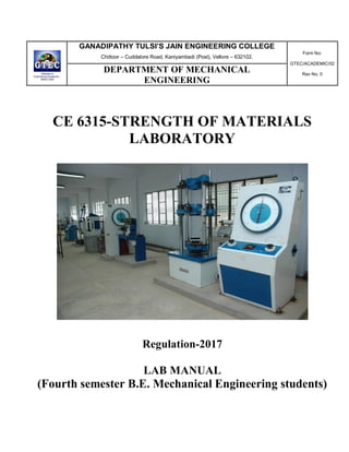
- 1. GANADIPATHY TULSI’S JAIN ENGINEERING COLLEGE Chittoor – Cuddalore Road, Kaniyambadi (Post), Vellore – 632102. Form No: GTEC/ACADEMIC/02 Rev No. 0 DEPARTMENT OF MECHANICAL ENGINEERING CE 6315-STRENGTH OF MATERIALS LABORATORY Regulation-2017 LAB MANUAL (Fourth semester B.E. Mechanical Engineering students)
- 2. CE6315 STRENGTH OF MATERIALS LABORATORY L T P C 0 0 3 2 OBJECTIVES To supplement the theoretical knowledge gained in Mechanics of Solids with practical testing for determining the strength of materials under externally applied loads. This would enable the student to have a clear understanding of the design for strength and stiffness. LIST OF EXPERIMENTS 1. Tension test on a mild steel rod 2. Double shear test on Mild steel and Aluminium rods 3. Torsion test on mild steel rod 4. Impact test on metal specimen 5. Hardness test on metals - Brinell and Rockwell Hardness Number 6. Deflection test on beams 7. Compression test on helical springs 8. Strain Measurement using Rosette strain gauge 9. Effect of hardening- Improvement in hardness and impact resistance of steels. 10. Tempering- Improvement Mechanical properties Comparison i) Unhardened specimen (ii) Quenched Specimen and (iii) Quenched and tempered specimen. 11. Microscopic Examination of (i) Hardened samples and (ii) Hardened and tempered samples. TOTAL: 45 PERIODS OUTCOMES: • Ability to perform different destructive testing • Ability to characteristic material
- 3. LIST OF EQUIPMENT FOR BATCH OF 30 STUDENTS S.NO NAME OF THE EQUIPMENT QUANTITY 1 Universal Tensile Testing machine with double 1 shear attachment –40 Ton Capacity 1 2 Torsion Testing Machine (60 NM Capacity) 1 3 Impact Testing Machine (300 J Capacity) 1 4 Brinell Hardness Testing Machine 1 5 Rockwell Hardness Testing Machine 1 6 Spring Testing Machine for tensile and compressive loads (2500 N) 1 7 Metallurgical Microscopes 3 8 Muffle Furnace (800 °C) 1
- 4. A LIST OF BASIC SAFETY RULES 1. When you handle chemicals wear eye protection (chemical splash goggles or full face shield). 2. When you work with furnaces for heat treatment procedures or other thermally activated equipment you should use special gloves to protect your hands. 3. Students should wear durable clothing that covers the arms, legs, torso and feet. (Note: sandals, shorts, tank tops etc. have no place in the lab. Students inappropriately dressed for lab, at the instructors discretion, be denied access) 4. To protect clothing from chemical damage or other dirt, wear a lab apron or lab coat. Long hair should be tied back to keep it from coming into contact with lab chemicals or flames. 5. In case of injury (cut, burn, fire etc.) notify the instructor immediately. 6. In case of a fire or imminently dangerous situation, notify everyone who may be affected immediately; be sure the lab instructor is also notified. 7. If chemicals splash into someone's eyes act quickly and get them into the eye wash station, do not wait for the instructor. 8. In case of a serious cut, stop blood flow using direct pressure using a clean towel, notify the lab instructor immediately. 9. Eating, drinking and smoking are prohibited in the laboratory at all times. 10. Never work in the laboratory without proper supervision by an instructor. 11. Never carry out unauthorized experiments. Come to the laboratory prepared. If you are unsure about what to do, please ask the instructor. 12. Always remember that HOT metal or ceramic pieces look exactly the same as COLD pieces are careful what you touch. 13. Know the location and operation of: - Fire Alarm Boxes - Exit Doors - Telephones
- 5. LABARATORY CLASSES - INSTRUCTIONS TO STUDENTS 1. Students must attend the lab classes with ID cards and in the prescribed uniform. 2. Boys-shirts tucked in and wearing closed leather shoes. Girls_ students with cut shoes, overcoat, and plait incite the coat. Girls_ students should not wear loose garments. 3. Students must check if the components, instruments and machinery are in working condition before setting up the experiment. 4. Power supply to the experimental set up/ equipment/ machine must be switched on only after the faculty checks and gives approval for doing the experiment. Students must start to the experiment. Students must start doing the experiments only after getting permissions from the faculty. 5. Any damage to any of the equipment/instrument/machine caused due to carelessness, the cost will be fully recovered from the individual (or) group of students. 6. Students may contact the lab in charge immediately for any unexpected incidents and emergency. 7. The apparatus used for the experiments must be cleaned and returned to the technicians, safely without any damage. 8. Make sure, while leaving the lab after the stipulated time, that all the power connections are switched off. 9. EVALUATIONS: - All students should go through the lab manual for the experiment to be carried out for that day and come fully prepared to complete the experiment within the prescribed periods. Student should complete the lab record work within the prescribed periods. - Students must be fully aware of the core competencies to be gained by doing Experiment/exercise/programs. - Students should complete the lab record work within the prescribed periods. - The following aspects will be assessed during every exercise, in every lab class and marks will be awarded accordingly: - Preparedness, conducting experiment, observation, calculation, results, record presentation, basic understanding and answering for viva questions. - In case of repetition/redo, 25% of marks to be reduced for the respective component.
- 6. NOTE 1 Preparation means coming to the lab classes with neatly drawn circuit diagram /experimental setup /written programs /flowchart, tabular columns, formula, model graphs etc in the observation notebook and must know the step by step procedure to conduct the experiment. Conducting experiment means making connection, preparing the experimental setup without any mistakes at the time of reporting to the faculty. Observation means taking correct readings in the proper order and tabulating the readings in the tabular columns. Calculation means calculating the required parameters using the approximate formula and readings. Result means correct value of the required parameters and getting the correct shape of the characteristics at the time of reporting of the faculty. Viva voice means answering all the questions given in the manual pertaining to the experiments. Full marks will be awarded if the students perform well in each case of the above component. NOTE 2 Incompletion or repeat of experiments means not getting the correct value of the required parameters and not getting the correct shape of the characteristics of the first attempt. In such cases, it will be marked as “IC” in the red ink in the status column of the mark allocation table given at the end of every experiment. The students are expected to repeat the incomplete the experiment before coming to the next lab. Otherwise the marks for IC component will be reduced to zero. NOTE 3 Absenteeism due to genuine reasons will be considered for doing the missed experiments. In case of power failure, extra classes will be arranged for doing those experiments only and assessment of all other components preparedness; viva voice etc. will be completed in the regular class itself. NOTE 4 The end semester practical internal assessment marks will be based on the average of all the experiments.
- 7. CONTENT S.No Experiment Name Page No Date Remarks Ist Cycle Experiments 1 Tension Test on mild steel rod 2 Torsion test on mild steel rod 3 Impact test on metal specimen 4 Compression test on helical springs 5 Hardness test on metals (a) Brinnell Hardness number (b) Rockwell Hardness number IInd Cycle Experiments 6 Deflection test on beams 7 Double shear test on mild steel 8 Effect on Hardening- Improvement in Hardness of steels 9 Tempering- Improvement Mechanical properties comparison (a) Unhardened specimen (b) Quenched specimen (c) Quenched and tempered specimen 10 Microscopic Examination of (a) Hardened samples (b) Hardened and tempered samples.
- 8. TENSILE TEST SET UP Release valve Lower Jaw Lower Jaw Specime n Upper Jaw BA SE Controlling valve Dial
- 9. Ex.No:1 DATE: TENSILE TEST ON MILD STEEL ROD AIM: To determine the tensile strength, percentage of elongation, percentage of reduction area, Young‟s modulus of the given mild steel rod by Universal Testing Machine. APPARATUS REQUIRED: Universal testing machine. Mild steel rod specimen. Vernier caliper. Metre scale. Graph sheet THEORY: The tensile test is most applied one, of all mechanical tests. In this test ends of test piece and fixed into grips connected to a straining device and to a load measuring device. If the applied load is small enough, the deformation of any solid body is entirely elastic. An entirely deformed solid will return to its original form as soon as load is removed. However, if the load is too large, the material can be deformed permanently. The initial part of the tension curve, which is recoverable immediately after unloading ,is termed as elastic and the rest of the curve, which represents the manner in solid undergoes plastic deformation is termed as plastic. The stress below which the deformation is essentially entirely elastic is known as the yield strength of material. In some materials the onset of plastic deformation is denoted by a sudden drop in load indication both an upper and a lower yield point. However, some materials do not exhibit a sharp yield point. During plastic deformation, at larger extensions strain hardening cannot compensate for the decrease in section and thus the load passes through the maximum and then begins to decrease. At this stage the “ultimate strengths”, which is defined as the ratio of the load on the specimen to the original cross sectional are, reaches the maximum value. Further loading will eventually cause „neck formation and rupture. Usually a tension testis conducted at room temperature and the tensile load is applied slowly. During this test either round of flat specimens may be used. The round specimens may have smooth, shouldered or threaded ends. The load on the specimen is applied mechanically or hydraulically depending on the type of testing machine.
- 10. In actual practice when a beam is loaded the shear force at a section always comes to play along with bending moment. It has been observed that the effect of shearing stress as compared to bending stress is quite negligible. But sometimes, the shearing stress at a section assumes much importance in design calculations. Universal testing machine is used for performing shear, compression and tension. There are two types of UTM. (i)Screw type, (ii) Hydraulic type. Hydraulic machines are easier to operate. They have a testing unit and control unit connected to each other with hydraulic pipes. It has a reservoir of oil, which is pumped into a cylinder, which has a piston. By this arrangement, the piston is made to move up. Same oil is taken in a tube to measure the pressure. This causes movement of the pointer, which gives reading for the load applied. FORMULA USED: Yield Stress 𝜎y = 𝑃𝑦 𝐴 in N/mm2 . Ultimate Stress 𝜎u = 𝑃𝑢 𝐴 in N/mm2 . Nominal Breaking Stress 𝜎nb = 𝑃 𝑏 𝐴 in N/mm2 . Actual Breaking Stress 𝜎ab = 𝑃 𝑏 𝐴1 in N/mm2 . Strain 𝜀 = 𝛿𝑙 𝑙 Young‟s modulus E = ζ ε in N/mm2 . Percentage of elongation = 𝛿𝑙 𝑙 x100 in % Percentage of reduction area = 𝐴−𝐴1 𝐴 in % Where Py : Yield load in N A : Cross section area of MS rod in mm2 δl : Increase/ change in length in mm l : Gauge length of MS rod in mm A1: Cross section area of rod after tested in mm2 Pu : Ultimate load in N
- 11. Pb : Breaking load in N About UTM:- The tensile test is conducted on UTM. It is hydraulically operates a pump, oil in oil sump, load dial indicator and central buttons. The left has upper, middle and lower cross heads i.e; specimen grips (or jaws). Idle cross head can be moved up and down for adjustment. The pipes connecting the lift and right parts are oil pipes through which the pumped oil under pressure flows on left parts to more the cross-heads. PRECAUTIONS: 1. The specimen should be prepared in proper dimensions. 2. The specimen should be properly to get between the jaws. 3. Take reading carefully. 4. After breaking specimen stop to m/c. PROCEDURE: 1. Measure the diameter of the rod using Vernier caliper. 2. Measure the original length of the rod. 3. Select the proper jaw inserts and complete the upper and lower chuck assemblies. 4. Apply some graphite grease to the tapered surface of the grip surface for the Smooth motion. 5. Operate the upper cross head grip operation handle and grip fully the upper end of the test piece. 6. The left valve in UTM is kept in fully closed position and the right valve in normal open position. 7. Open the right valve and close it after the lower table is slightly lifted. 8. Adjust the load to zero by using large push button (This is necessary to remove the dead weight of the lower table, upper cross head and other connecting parts of the load). 9. Operate the lower grip operation handle and lift the lower cross head up and grip fully the lower part of the specimen. Then lock the jaws in this position by operating the jaw locking handle. 10. Turn the right control valve slowly to open position (anticlockwise) until we get a desired loadings rate. 11. After that we will find that the specimen is under load and then unclamp the locking handle. 12. Now the jaws will not slide down due to their own weight. Then go on increasing the load. 13. At a particular stage there will be a pause in the increase of load. The load at this point is noted as yield point load.
- 12. 14. Apply the load continuously, when the load reaches the maximum value. This is noted as ultimate load. 15. Note down the load when the test piece breaks, the load is said to be a breaking load. 16. When the test piece is broken close the right control valve, take out the broken pieces of the test piece. Then taper the left control valve to take the piston down. OBSERVATIONS: o Diameter of steel rod: S.No. Main Scale Reading MSR Vernier Scale Coincide VSC Vernier Scale Reading VSR = VSC X LC Total Reading TR = MSR + VSR Unit mm division mm mm Average o Original length =……………….mm o Gauge length l = …………………mm o Neck diameter of the rod =……………….mm
- 13. TABULATION: S.No. Elongation 𝜹𝒍 Load P Strain 𝜀 Stress 𝜎 Unit mm N % N/mm2 GRAPH: A graph is drawn between strain vs stress by taking strain along the X-axis and stress along the Y-axis. Y X StressinN/mm2 Strain in % ∆𝜎 ∆𝜀
- 14. RESULT: Young‟s modulus E=………………….N/mm2 . Actual Breaking Stress =………………….N/mm2 . Ultimate Stress =………………….N/mm2 . Percentage of Elongation =……………
- 15. Ex.No.2 DATE: TORSION TEST ON MILD STEEL SPECIMEN AIM: To conduct the torsion test on the given specimen for the following 1. Modulus of rigidity 2. Shear stress APPARATUS REQUIRED: 1. Vernier caliper 2. Scale FORMULA USED: 1. Modulus of rigidity, C = N/mm2 Where, α =angle of Twist 2. Shear stress (t) =TR/L N/mm2 THEORY: A torsion test is quite instrumental in determining the value of rigidity (ratio of shear stress to shear strain) of a metallic specimen. The value of modulus of rigidity can be found out through observations made during the experiment by using the torsion equation. T/ Ip =Cθ /L or C=TL/Iθ Where T=torque applied, Ip= polar moment of inertia, C=modulus of rigidity, θ= Angle of twist (radians), and l= gauge length. In the torque equipment refer fig. One end of the specimen is held by a fixed support and the other end to a pulley. The pulley provides the necessary torque to twist the rod by addition of weights (w). The twist meter attached to the rod gives the angle of twist. Precautions: 1. The specimen should be prepared in proper dimensions. 2. The specimen should be properly to get between the jaws. 3. Take reading carefully. PROCEDURE: 1. Measure the diameter and length of the given rod. 2. The rod is fixing in to the grip of machine. 3. Set the pointer on the torque measuring scale. 4. The handle of machine is rotate in one direction.
- 16. 5. The torque and angle of test are noted for five degree. 6. Now the handle is rotated in reverse direction and rod is taken out OBSERVATION: Diameter of the Specimen = mm Gauge length of the Specimen = mm TABULATION: S.No Angle Of Twist Angle Of Twist Torque Modulus Of Rigidity Shear Stress Unit Degree Radian Kgf/cm Nm N/m2 N/m2 RESULT: Thus the torsion test on given mild steel specimen is done and the values of modulus of rigidity and shear stress are calculated.
- 17. Scale Pillar 3 0 0 J 0 J 0 J Base Strikin g hamme r 40m m Figure shows charpy setup. Striking edge
- 18. Striking hammer Scale Suppor t Specimen Pillar Base Striking edge. 22mm 45o 2mm 10mm 10mm 28mm 75mm
- 19. Ex.No:3 DATE: IMPACT TEST ON METAL SPECIMEN AIM: To determine the impact strength of the given material using Charpy and Izod impact test. APPARATUS REQUIRED: Impact testing machine . Metal specimen Vernier calliper. THEORY: An impact test signifies toughness of material that is ability of material to absorb energy during plastic deformation. Static tension tests of un-notched specimens do not always reveal the susceptibility of a metal to brittle fracture. This important factor is determent by impact test. Toughness takes into account both the material. Several engineering material have to with stand impact or suddenly loads while in service. Impact strengths are generally lower as compared to strengths achieved under slowly applied loads of all types of impact tests, the notched bar test are most extensively used. Therefore, the impact test measures the energy necessary to fracture a standard notched bar by applying an impulse load. The test measures the notch toughness of material under shocking loading. Values obtained from these tests are not of much utility to design problems directly and are highly arbitrary. Still it is important to note that it provides a good way of comparing toughness of various materials or toughness of same material under different conditions. This test can also be used to assess the ductile brittle transition temperature of the material occurring due to lowering of temperature. In manufacturing locomotive wheels, coins, connecting rods etc. the components are subjected to impact (shock) loads. These loads are applied suddenly. The stress induced in these components is many times more than the stress produced by gradual loading. Therefore, impact tests are performed to asses shock absorbing capacity of materials subjected to suddenly applied loads. These capabilities are expressed as (i) Rupture energy (ii) Modulus of rupture and (iii) Notch impact strength. Two types of notch impact tests are commonly- 1. Charpy test. 2. Izod test. In Izod test, the specimen is placed as „cantilever beam‟. The specimens have V- shaped notch of 45°. U-shaped notch is also common. The notch is located on tension side of specimen during impact loading. Depth of notch is generally taken as t/5 to t/3 where„t‟ is thickness of the specimen.
- 20. In charpy test, the specimen is placed as „cantilever beam‟. The specimens have V-shaped notch of 45°.U-shaped notch is also common. The notch is located on tension side of specimen during impact loading. Depth of notch is generally taken as t/5 to t/3 where „t‟ is thickness of the specimen. FORMULA USED: Experimental Impact strength I = 𝐞 𝐀 in Joules/mm2 . { Impact strength = J/mm2 } Where e - Net impact energy observed in joules A - Cross section area of specimen at the notch in mm2 m - Mass of pendulum g - Acceleration due to gravity in m/s2 - Angle through which the pendulum falls - Angle through which the pendulum rises R - Distance between the centre of gravity of the pendulum and the axis of rotation in mm. PRECAUTIONS: 1. The specimen should be prepared in proper dimensions. 2. Take reading more frequently. 3. Make the loose pointer in contact with the fixed pointer after setting the Pendulum. 4. Do not stand in front of swinging hammer or releasing hammer. 5. Place the specimen proper position.
- 21. PROCEDURE: Measure the dimension of the specimen. Check whether charpy striker is in position and mount the latching tube on the housing.(it will be 135○ with the vertical pillar.) Lift the pendulum by hand and fix it with latching tube. Let the needle of dial at 300 joules and release the pendulum for the frictional losses. If there is any frictional loss, note down in tabular column. Again lift the pendulum by hand and fix it with the latching tube. Place the specimen on the specimen support as a simply support beam. Align the notch in such a way that its face should be opposite to the direction of the striker and it is at the center. Adjust the pointer to 300 joules. Release the pendulum to allow swinging freely and to break the specimen. After the rupture of specimen, stop the pendulum slowly by apply brake lever. Note the absorbed energy from the dial as indicated by the indicating pointer. OBSERVATIONS: - Mass of the pendulum m =……………….kg. - Length of the pendulum l =……………….mm. - Energy loss due to friction ef = ……………..joules. - Size of the specimen =………………………mm3 . TABULATION: Method Area of specimen A(mm2 ) Impact energy e1 (J) Friction loss ef (J) Net impact energy e = e1- ef (J) Impact strength I (J/mm2 ) Izod Charpy
- 22. RESULT: Impact strength of the given material in charpy method: - I is ………………….joules/mm2 . Impact strength of the given material in Izod method: - I is ………………….joules/mm2 .
- 23. EXP NO: 4 DATE: ROCKWELL HARDNESS TEST AIM: To determine the hardness of a given specimen by using Rockwell hardness testing machine. APPARATUS REQUIRED: Rockwell hardness testing machine. Specimens. THEORY: - The hardness of a material is resistance to penetration under a localized pressure or resistance to abrasion. Hardness tests provide an accurate, rapid and economical way of determining the resistance of materials to deformation. There are three general types of hardness measurements depending upon the manner in which the test is conducted: a. Scratch hardness measurement, b. Rebound hardness measurement c. Indention hardness measurement. In scratch hardness method the material are rated on their ability to scratch one another and it is usually used by mineralogists only. In rebound hardness measurement, a standard body is usually dropped on to the material surface and the hardness is measured in terms of the height of its rebound .The general means of judging the hardness is measuring the resistance of a material to indentation. The indenters usually a ball cone or pyramid of a material much harder than that being used. Hardened steel, sintered tungsten carbide or diamond indenters are generally used in indentation tests; a load is applied by pressing the indenter at right angles to the surface being tested. The hardness of the material depends on the resistance which it exerts during a small amount of yielding or plastic. The resistance depends on friction, elasticity, viscosity and the intensity and distribution of plastic strain produced by a given tool during indentation.
- 24. PRECAUTIONS Thickness of the specimen should not be less than 8 times the depth of indentation to avoid the deformation to be extended to the opposite surface of a specimen. Indentation should not be made nearer to the edge of a specimen to avoid unnecessary concentration of stresses. In such case distance from the edge to the center of indentation should be greater than 2.5 times diameter of indentation. Rapid rate of applying load should be avoided. Load applied on the ball may rise a little because of its sudden action. Also rapidly applied load will restrict plastic flow of a material, which produces effect on size of indentation. OBSERVATION: o The dimension of given specimen1 is………………………………mm3 . o The dimension of given specimen2 is………………………………mm3 . o The dimension of given specimen3 is………………………………mm3 PROCEDURE: Measure the dimensions of the given specimen .Place the specimen securely upon the anvil. Elevate the specimen so that it come into contact with the penetrate and put the specimen under a preliminary or minor load of 100+2N without shock. Apply the major load 900N by loading lever. Watch the pointer until it comes to rest. Remove the major load. Read the Rockwell hardness number or hardness scale.
- 25. TABULATION: S.No. Specimens RHN Reading Rockwell Hardness Number MeanTrail 1 Trail 2 Trail 3 1 2 3 4 RESULT:- Rockwell hardness of the given specimen is………………………….
- 26. EXP NO: 5 DATE: BRINELL HARDNESS TEST AIM: To determine the hardness of the given specimen using Brinell hardness test. APPPARATUS REQUIRED: Brinell hardness tester. Specimens. Ball indenter. Microscope. FORMULA USED: Brinell Hardness Number = 2P πD D− D2−d2 in HBN Where, P is load applied in kg, D is the diameter of ball indenter in mm and d is the diameter of indentation in mm. THEORY: Hardness of a material is generally defined as Resistance to the permanent indentation under static and dynamic load. When a material is required to use under direct static or dynamic loads, only indentation hardness test will be useful to find out resistance to indentation. In Brinell hardness test, a steel ball of diameter (D) is forced under a load (P) on to a surface of test specimen. Mean diameter (d) of indentation is measured after the removal of the load (P).
- 27. PRECAUTIONS: Thickness of the specimen should not be less than 8 times the depth of indentation to avoid the deformation to be extended to the opposite surface of a specimen. Indentation should not be made nearer to the edge of a specimen to avoid unnecessary concentration of stresses. In such case distance from the edge to the center of indentation should be greater than 2.5 times diameter of indentation. Rapid rate of applying load should be avoided. Load applied on the ball may rise a little because of its sudden action. Also rapidly applied load will restrict plastic flow of a material, which produces effect on size of indentation. Surface of the specimen is well polished, free from oxide scale and any foreign material. OBSERVATION: o The dimension of given specimen1 is………………………………mm3 . o The dimension of given specimen2 is………………………………mm3 . o The dimension of given specimen3 is………………………………mm3 . o Diameter of indenter D is ………………….mm PROCEDURE Load to be applied for hardness test should be selected according to the expected hardness of the material. However test load shall be kept equal to 30 times the square of the diameter of the ball in mm. Where ball diameter, generally taken as 10 mm. Apply the load for a minimum of 15 seconds to 30 seconds. [if ferrous metals are to be tested time applied will be 15 seconds and for softer metal 30 seconds] Remove the load and measure the diameter of indentation nearest to 0.02 mm using microscope (projected image) Calculate Brinell hardness number (HB). Brinell hardness numbers can be obtained from equation, knowing diameter of indentation, diameter of the ball and load applied. Take average of five values of indentation of each specimen. Obtain the Brinell hardness number from equation and Compare with Rockwell hardness tests.
- 28. TABULATION: S.No . Specimens Load P (kg) Diameter of indentation d is mm Brinell Hardness Number Trial 1 Trial 2 Trial 3 Mean d 1 2 3 4 RESULT: The Brinell hardness number of the Specimen is………………….HBN
- 30. EXP NO: 6 DATE: DEFLECTION TEST ON BEAMS AIM: To conduct the deflection test on beams and to find the young‟s modulus and bending stress of the material of the given beam simply supported at the ends and carrying a concentrated load at the centre. APPARATUS REQUIRED: Dial Indicator. Beam of different cross-sections and materials. Knife edge Supports. Weights. Vernier calliper. FORMULA USED: Young‟s Modulus E = 𝑤𝑙3 48𝛿𝐼 in N/mm2 . Bending moment M = 𝑤𝑙 4 in Nmm. Moment of Inertia I = bd3 12 in mm4 Bending stress 𝜎b = M.Y I in N/mm2 . Where, l is length of span of beam in mm, b is breadth of beam in mm, d is depth of beam in mm, w is weights in N, δ is deflection of beam at centre in mm and Y is distance of the top fiber of the beam from the neutral axis in mm. PROCEDURE: Adjust a knife edge supports along the bed so that they are symmetrical with respect to the length of the beam. Place the beam on the knife edges of the supports so as to project equally beyond each knife edge. Adjust the dial gauge reading as „zero‟ and the load is applied at the centre of the beam. Add a weight 1kg and note the deflection from dial indicator.
- 31. Take readings by addition 1kg each time till you have minimum of six readings. Find the deflection (𝛿) in each case from the dial indicators. Draw a graph between load (w) and deflection (δ) on the graph, choose convenient point find the corresponding values of w and 𝛿. Calculate the value of „E‟. Calculate the bending stresses for different loads by using formulae. OBSERVATIONS: o Width of the beam b =……………..mm. o Depth of the beam d =………………mm. o Length of span l =………………….mm. o Moment of inertia I = bd3 12 =…………… mm4 . TABULATION: S.No. Load w Bending moment M Bending stress 𝜎b Deflection δ Young‟s Modulus E Unit kg N Nmm N/mm2 mm N/mm2 Mean E =
- 32. GRAPH: A graph is drawn between deflection vs load by taking deflection along the X-axis and load along the Y-axis. RESULT:- From theoretical, - The young‟s modulus of the given beam materials E =………………..N/mm2 . - The maximum bending stress of the given beam for maximum load 𝜎b =….N/mm2 . From graph, - The young‟s modulus of the given beam materials E =………………..N/mm2 . - The maximum bending stress of the given beam for maximum load 𝜎b =….N/mm2 . Y X LoadinN Deflection in mm ∆W ∆𝛿
- 33. Release valve Lower Jaw Lower Jaw Upper Jaw BAS E Controlling valve Dial DOUBLE SHEAR TEST SET UP
- 34. EXP NO: 7 DATE: DOUBLE SHEAR TEST ON MILD STEEL AIM: To determine the ultimate shear strength and safe strength of a given specimen. APPARATUS REQUIRED: Universal Testing Machine (UTM). Vernier calliper. Test specimen. FORMULA USED: Ultimate shear strength 𝛔u = Pu 2A in N/mm2 . Safe shear strength 𝛔s = σu FoS ∗ in N/mm2 . Where, Pu is ultimate load in N, A is cross section area of specimen in mm2 , FoS is factor of safety. *Note: the factor of safety for gradually applied load is varies from 2 to 4. THEORY: The tensile test is most applied one, of all mechanical tests. In this test ends of test piece and fixed into grips connected to a straining device and to a load measuring device. If the applied load is small enough, the deformation of any solid body is entirely elastic. An entirely deformed solid will return to its original form as soon as load is removed. However, if the load is too large, the material can be deformed permanently. The initial part of the tension curve, which is recoverable immediately after unloading ,is termed as elastic and the rest of the curve, which represents the manner in solid undergoes plastic deformation is termed as plastic. The stress below which the deformation is essentially entirely elastic is known as the yield strength of material. In some materials the onset of plastic deformation is denoted by a sudden drop in load indication both an upper and a lower yield point. However, some materials do not exhibit a sharp yield point. During plastic deformation, at larger extensions strain hardening cannot compensate for the
- 35. decrease in section and thus the load passes through the maximum and then begins to decrease. At this stage the “ultimate strengths”, which is defined as the ratio of the load on the specimen to the original cross sectional are, reaches the maximum value. Further loading will eventually cause „neck formation and rupture. Usually a tension testis conducted at room temperature and the tensile load is applied slowly. During this test either round of flat specimens may be used. The round specimens may have smooth, shouldered or threaded ends. The load on the specimen is applied mechanically or hydraulically depending on the type of testing machine. In actual practice when a beam is loaded the shear force at a section always comes to play along with bending moment. It has been observed that the effect of shearing stress as compared to bending stress is quite negligible. But sometimes, the shearing stress at a section assumes much importance in design calculations. Universal testing machine is used for performing shear, compression and tension. There are two types of UTM. (i)Screw type, (ii) Hydraulic type. Hydraulic machines are easier to operate. They have a testing unit and control unit connected to each other with hydraulic pipes. It has a reservoir of oil, which is pumped into a cylinder, which has a piston. By this arrangement, the piston is made to move up. Same oil is taken in a tube to measure the pressure. This causes movement of the pointer, which gives reading for the load applied. PRECAUTIONS: 1. The specimen should be prepared in proper dimensions. 2. The specimen should be properly to get between the jaws. 3. Take reading carefully. 4. After breaking specimen stop to m/c. PROCEDURE: Measure the dimensions of the given specimen. Calculate the area of the specimen from the measured dimensions. Suitable rings are to be selected for the double shear test. The ring diameter is chosen according the dimensions of specimen. Keep the specimen in the ring. Initially the release valve is kept opened and the control valve is kept close fully. Bring down the lower cross bar down by operating the cross head push button provided on the control panel so that the attachment fixed with the cross bar touches the specimen. Close the release valve fully.
- 36. Switch ON the hydraulic push button. Open the control valve gradually. When the specimen is sheared fully, close the control valve and switch OFF the hydraulic mechanism. Open the release valve fully. Then, note down the ultimate load shown in load dial. Calculate the ultimate shear strength and safe strength of the given specimen. OBSERVATIONS: Double shear Test 1. Diameter of the specimen (d) = 2. Cross sectional area in double shear, (A) = 2 x π d2 / 4 mm2 3. Shear Load taken by specimen at the time of failure (P) = o Diameter of specimen D: S.No. Main Scale Reading MSR Vernier Scale Coincide VSC Vernier Scale Reading VSR = VSC X LC Total Reading TR = MSR + VSR Unit mm division mm mm Average D TABULATION: S.No. Specimen Area of specimen Maximum Shear load on specimen Maximum Shear strength Safe Shear strength Unit mm mm2 N N/mm2 N/mm2
- 37. RESULT:- Ultimate shear strength of the given specimen 𝜎u = ……………………..N/mm2 . Safe shear strength of the given specimen 𝜎s =………………………….N/mm2 .
- 38. EXP NO: 8 DATE: EFFECT ON HARDENING- IMPROVEMENT IN HARDNESS OF STEELS AIM To find hardness number for unhardened, hardened specimen or Quenched and tempered specimen and compare mechanical properties. MATERIAL AND EQUIPMENT Unhardened specimen, Hardened or Quenched and tempered specimen, muffle furnace, Rockwell testing machine. PROCEDURE HARDENING: It is defined as a heat treatment process in which the steel is heated to a temperature within or above its critical range, and held at this temperature for a considerable time to ensure thorough penetration of the temperature inside the component and allowed to cool by quenching in water, oil or brine solution. Case (I) - Unhardened specimen 1. Choose the indenter and load for given material. 2. Hold the indenter in indenter holder rigidly 3. Place the specimen on the anvil and raise the elevating screw by rotating the hand wheel up to the initial load. 4. Apply the major load gradually by pushing the lever and then release it as before. 5. Note down the readings in the dial for corresponding scale.
- 39. 6. Take min 5 readings for each material. Case (II) - For Hardened specimen 1. Keep the specimen in muffle furnace at temperature of 700˚ to 850˚ for 2 hours 2. The specimen is taken from muffle furnace and quenched in water or oil. 3. Then above procedure is followed to test hardness Case (III) - For Tempered specimen 1. Keep the specimen in muffle furnace at temperature of 650˚ for 2 hours 2. Allow the specimen for air cooling after taking from muffle furnace 3. Then same procedure is followed foe the specimen
- 40. TABULATION: S.No. Test Test Specimen Hardness Reading Hardness Number MeanTrail 1 Trail 2 Trail 3 1 Rockwell 2 Brinell RESULT: 1. Rockwell Hardness in Mild steel 1. Rockwell hardness number before Hardening = 2. Rockwell hardness number after Hardening = 3. Rockwell hardness number before tempering = 4. Rockwell hardness number after tempering =
- 41. COMPRESSION TEST SET UP Frame Base Spring
- 42. EXP NO : 9 DATE: COMPRESSION TEST ON HELICAL SPRING AIM: To conduct the compression test on helical springs and to find the rigidity modulus and stiffness of the material of the given helical spring. APPARATUS REQUIRED: Helical spring. Vernier calliper. Spring tester setup. FORMULA USED: Deflection 𝛿 = 64wR3n sec α d4 cos α 2 C + 2 sin α 2 E in mm. Stiffness of spring K = w δ in N/mm. α = tan−1 p 2πR Mean radius of spring R = D−d 2 in mm. Where, d is diameter of spring wire in mm, w is weights in N, δ is deflection of spring in mm, nt is total No. of turns, R is mean radius of the spring in mm, C is rigidity modulus of spring material in N/mm2 , E is young‟s modulus of spring materials in N/mm2 , α is angle of helix, and lo is length of spring in mm. Plain Ends Closed Ends Plain Ends Ground Closed Ends Ground* Active Coils, Na Nt Nt-2 Nt-1 Nt-2 Free Length, Lo Nap+d Nap+3d (Na+1)p Nap+2d Solid Length, Ls (Na+1)d (Na+1)d (Na+1)d (Na+2)d
- 43. Pitch, p (Lo-d)/Na (Lo-3d)/Na Lo/(Na+1) (Lo-2d)/Na * The equations shown for the Closed and Ground end type assume one inactive coil at each end of the spring. The Helical Spring Design module allows the user to specify any number of inactive coils for a spring with Closed and Ground ends. Table shows effect of ends treatment. OBSERVATIONS: o Diameter of spring coil (D) : S.No. Main Scale Reading MSR Vernier Scale Coincide VSC Vernier Scale Reading VSR = VSC X LC Total Reading TR = MSR + VSR Unit mm division mm mm Average D o Diameter of spring wire (d) : S.No. Main Scale Reading MSR Vernier Scale Coincide VSC Vernier Scale Reading VSR = VSC X LC Total Reading TR = MSR + VSR Unit mm division mm mm Average d
- 44. o Free length of spring lo =……………..mm. o Total No. of turns nt =……………….. turns. o Pitch p = …………………mm. o modulus of elasticity E =………………N/mm2 PROCEDURE: Measure the diameter of the given spring wire with help of Vernier calliper.. Measure the outer diameter of spring with help of Vernier calliper. Count the number of turns of the given spring. The spring is placed on the setup which is produced in the spring tester. Apply the compressive load gradually by rotating hand wheel. Note the deflection of spring when it is loading and unloading. Plot a curve between load and deflection with load on y axis and deflection on x axis. Rigidity modulus of spring can be determined by using formula given. Slope of the curve will give stiffness of the spring. After carrying out the experiment unload the spring. GRAPH: A graph is drawn between deflection vs load by taking deflection along the X-axis and load along the Y-axis. Y X LoadinN Deflection in mm ∆W ∆𝛿
- 45. TABULATION: S.No. Load w Scale Reading Deflection δloading unloading Unit N mm mm mm RESULT:- From theoretical, - The stiffness of the given helical spring K =………………..N/mm. - The modulus of rigidity of given spring material C =…………..N/mm2 . From graph, - The stiffness of the given helical spring K =………………..N/mm. - The modulus of rigidity of given spring material C =…………..N/mm2 .
- 46. EXP NO : 10 DATE: MICROSCOPIC EXAMINATION OF HARDENED AND TEMPERED SAMPLES AIM: To examine the microstructure of a given plain carbon steel sample before and after heat treatment. APPARATUS REQIRED: Belt grinder Simple disc polishing machine Stretching agent Emery sheet Muffle furnace THEORY: Sample specimen: i) Unbalanced specimen ii) Harden specimen iii) Tempered specimen Steel can be heat treated to high temperature to achieve the requirement harden and strength. The high operating stress need the high strength of hardened structure similarly tools such as like knives etc. as quenched hardened steels are so, brittle than even slight compact cause fracture. The heat treatment that reduces the brittleness of steel without significantly lowering the hardness and strength. Hardened steel must be tempered before use. Hardening: To increase the strength and hardness To improve the mechanical properties Hardening temperature-9000 c Holding time-1 hr Quenching medium - Water. Tempering: To reduce the stress To reduce the brittleness Tempering temperature-320°C Holding time-1 hr The specimen and is heated at a temperature which is determined using the microstructure the specimen quenching into oil. The given three samples are subjected to
- 47. the study of microstructure of the hardened metal. The micro structure of the unhardened sample is studied and hardness is found. The furnace which is maintained at temperature at 900°C for hardening. The sample is added to get austenite structure. The third sample is subjected to tempering process of is hold at 830°C is furnace for this and quenched in air.The micro structure of the third specimen is studied and hardness is formed. PROCEDURE: 1. Specimen is heated to temperature which is determined using the microscopic structure the specimen is quenched in oil. 2. The given samples are subjected to the study of micro structure and hardness. 3. The microstructure of the hardened sample is subjected. OBSERVATION: Specimen: Magnification: Composition: TABULATION: SAMPLES SAMPLE-1 (before hardening) SAMPLE-1 (after hardening) MICROSTRUCTURE RESULT: Thus the microstructure and the hardness of the given sample are studied and treatment is tabulated.