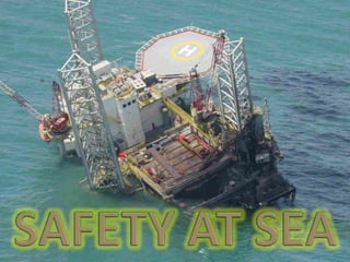
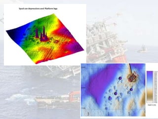
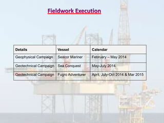
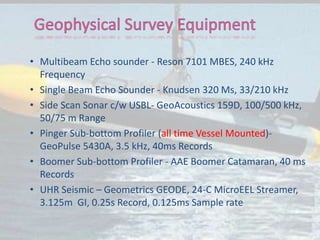
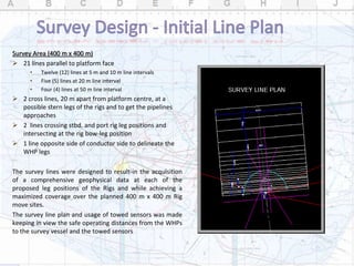
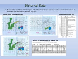
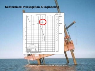
Rig: Maersk Victory
Date: 16 Nov 1996
Location: Gulf Saint Vincent. Australia
Operator: Apache Energy Ltd. (Australia).
1996 Punch-Through
Findings
The South Australia Department of Mines and Energy Resources (MESA) undertook an
investigation in May 1997 and determined that the immediate cause of damage was the failure
of the sub-sea sediments beneath the rig. There was no evidence of structural failure of the
Ocean Victory contributing to the incident. The report concluded that there was a failure to fully
evaluate the risks of a new drilling location, a failure to fully evaluate the geotechnical data of
the sub-sea sediments with particular reference to the load bearing capacity of the sub-sea
sediments, and a failure in management systems and procedures for locating the rig.
APRIL 2015
Recently some incidents been reported by Rigs and barges from offshore due to the
damaged and disturbed seabed and sub-bottom strata, it happened by an extensive
jacking up near Well Head Platforms (WHPs).
A comprehensive and elaborated Geophysical & Geotechnical Investigation campaign
for 61 sites been planned & designed by the Lead surveyor to acquire new data, as the
currently available data is aged and requires additional information at the proposed
Rig and barge Moves Site locations. additional locations added as demanded from
Drilling Department and Sites.
For this purpose a new Geophysical and Geotechnical Data Set has been obtained,
identifying any seabed and sub–seabed hazards.
New Locations out side our fields were also added to the scope.
Identify all possible constraints and hazards such as man-made, natural (punch-through) and geological
features, which may effect the operational or environmental integrity of a proposed drilling operation and to
allow appropriate operational practices to be put in place to mitigate any risks identified.
INITIAL SURVEY PLAN
Geophysical Site Survey:
• Conduct Geophysical Site Surveys at each given site for Rig Approach, an area of 400 m x 400 m at
WHPs to determine the seabed and sub-bottom strata at possible Leg Locations to learn the
hazards.
Geotechnical Investigations:
• Conduct Geotechnical Investigations comprising of 2 X geotechnical boreholes to twenty (20 m)
deep below seabed at given locations followed by jack-up leg penetration analysis reports for
expected Rigs/ Barges provided by the company at each site.
Review of the Geophysical survey Data, previously available Geotechnical Data and penetration
history to decide Number of Bore holes, Depth of Bore Holes below seabed and any specialised
testing requirements for un-seen hazards.
 Number of Bore holes, Depth of Bore Holes below seabed, Bore Hole locations been changed
during the surveys to get the best results and CPTs were conducted at several locations.
Fields:
Survey Sites are in Very Busy Operational Oil fields
Field is congested with current artificial islands construction related activities and Restricted access due to
heavy traffic in field; supply vessels, barges, support vessels/Drill Rigs.
Survey Sites:
Survey sites are measured 400m x 400m at Rig access face of the jackets
Small areas with limited manoeuvrability.
Target locations (BH locations) are very close to jacket faces
The nearest survey line is 10m from jacket face
Currents are the deciding factors for line plan and direction
Weather criteria for survey very stringent and weather forecast is paramount
No towing equipment within the first 40mtrs of jacket face
Accurate mapping of historic rig leg depressions (Size/depth/brittleness depressions/disturbed seabed etc.)
Sub-bottom data is paramount with MBES as the main seabed mapping tool within first 40mtrs
Vessel navigation is important and experienced Masters were onboard to do safe navigation.
Risk assessment approved and TRA prepare for each jacket site based on existing conditions
Seabed not conducive for good sub-bottom penetration
Lack of ideal sub-bottom tool (cost/towing etc. for UHR surveys)
Immediate data processing & review to decide the BH location and Numbers.
 Quickest Geophysical Survey’s review by Geophysicists and Geotechnical Engineers to decide on Bore Hole
location, numbers, depth and any extra tests.
 Many very urgent sites, as the rigs or barges were already planned.
 On-site data review to adjust testing programme if required.
 All survey sites are in operational fields & very close to WHPs.
 Coordination with Site to manage SIMOPS with many ongoing field activities.
 Rig’s aft legs locations in very close proximity to WHPs with vessel at only 10m from WHP.
 Shallow waters (<10m LAT) at some sites.
 Night drilling
 A total of 66 sites surveyed in Zakum, Satah, UAD and OC-1 Fields
 149 boreholes drilled at 62 sites in in Zakum, Satah, UAD and OC-1 Fields
 192,000 man-hours w/o LTI
 Quality data collected from Geophysical Survey and Geotechnical Investigation
 Successfully drilled borehole at shallow water-depth locations (WD < 10 m) with DP II vessel with drilling rig
mounted on cantilever frame
 Successfully salvaged two (2) no. lost drill pipes at OC-01 site
GEOTECHNICAL INVESTIGATION
 160,000 man-hours w/o LTI
 130 Hazard Observation reported to improve QHSE
 150 Tool-box talks
 Over 20 safety drills
 2 Incidents (2 x Loss of Equipment), Out side operational Fields.
GEOPHYSICAL SURVEY
 34,000 man-hours w/o LTI
 2 Hazard Observation reported to improve QHSE
 71 Tool-box talks
 7 safety drills
 ZERO Incidents
Details Vessel Calendar
Geophysical Campaign Seacor Mariner February – May 2014
Geotechnical Campaign Sea Conquest May-July 2014
Geotechnical Campaign Fugro Adventurer April, July-Oct 2014 & Mar 2015
• Multibeam Echo sounder - Reson 7101 MBES, 240 kHz
Frequency
• Single Beam Echo Sounder - Knudsen 320 Ms, 33/210 kHz
• Side Scan Sonar c/w USBL- GeoAcoustics 159D, 100/500 kHz,
50/75 m Range
• Pinger Sub-bottom Profiler (all time Vessel Mounted)-
GeoPulse 5430A, 3.5 kHz, 40ms Records
• Boomer Sub-bottom Profiler - AAE Boomer Catamaran, 40 ms
Records
• UHR Seismic – Geometrics GEODE, 24-C MicroEEL Streamer,
3.125m GI, 0.25s Record, 0.125ms Sample rate
Survey Area (400 m x 400 m)
 21 lines parallel to platform face
• Twelve (12) lines at 5 m and 10 m line intervals
• Five (5) lines at 20 m line interval
• Four (4) lines at 50 m line interval
 2 cross lines, 20 m apart from platform centre, at a
possible stern legs of the rigs and to get the pipelines
approaches
 2 lines crossing stbd. and port rig leg positions and
intersecting at the rig bow-leg position
 1 line opposite side of conductor side to delineate the
WHP legs
The survey lines were designed to result-in the acquisition
of a comprehensive geophysical data at each of the
proposed leg positions of the Rigs and while achieving a
maximized coverage over the planned 400 m x 400 m Rig
move sites.
The survey line plan and usage of towed sensors was made
keeping in view the safe operating distances from the WHPs
to the survey vessel and the towed sensors
 Available historical data within Company and with contractor were referenced in the evaluation of each site for
its potential hazards for the proposed Rig Move
Jack-up Zoning Plan for various Rigs
Previous Rig Move History to the Platform Sites
Previous Geotechnical Data
Pinger Sub-bottom Profiler Images
MBES and Side Scan Sonar Images
3-D view of Sonar Contact (Debris) from
MBES and Side Scan Sonar data within
the PW 131 platform site
Side Scan Sonar and MBES Image
showing Debris (PW-146 DB01) –PW 146
platform site
• Side Scan Sonar Image showing seabed
features close to PU3 / WHP3 Platform Site
• Side Scan Sonar Image showing seabed
features - PN 152 Platform Site
Side Scan Sonar Image showing seabed features and pipelines – PW 53
Platform Site
Side Scan Sonar Image showing Seabed features and pipelines - PW30
Platform Site
Side Scan Sonar Images
Borehole Drilling Plan
Based on the geophysical assessment and review by the Geotechnical Engineering Department, geotechnical
boreholes were according to three (3) scenarios:
One borehole
– at the Centre Position of the proposed Rig
Three boreholes
– one each at the proposed leg position
Two boreholes
– one at the bow-leg position
– one at the centre position of Port and
Stbd. Legs
Recommendations based on the Assessment
Geotechnical Investigation & Engineering
- Equipment : DP2 Vessel with rotary geotechnical drill rig
- Field Operations : Geotechnical Drilling
- Logging, In-situ Testing, O/b Laboratory Testing
- Geotechnical Data Interpretation & Field Reporting
- Onshore Laboratory Testing
- Final Borehole Log, Factual Reporting
- Engineering Report : Parameter Selection, LPA Curve
Geotechnical Investigation & Engineering
Equipment : Geotechnical Investigation
 FMR 200 : mounted on the central moon-pool
 FMR 202 : mounted on the cantilever (over-the-side)
- Seabed Frame (SBF) : Act as both a re-entry for the drill string and reaction mass.
- 53 kW HP Power Swivel with 175 N.m max. torque and 20T SWL.
- Drill-string and SBF motion compensator of 3 m stroke each.
- 2 Diesel driven hydraulic power packs to power the drill units.
 Open-hole rotatory drilling in Soil and coring in Rock
 Drill Pipe : API-type, 3.5 inch ID / CHD, 5.1 inch ID
 Rock Coring : PQ core barrel (83.5 mm – core dia) & Fugro-Marine core barrel (FMCB) (61.1 mm –
core dia).
 Push Sampling : 72mm dia, with constant rate of penetration into undisturbed strata.
 Hammer Sampling : 2” split spoon, 80kg hammer with 1.5m max. stroke.
 Cone Penetration Testing (CPT) : 90kN thrust capacity and 1.5m stroke, F5 type cone, refusal at 60
MPa.
Geotechnical Investigation & Engineering
Field Operations : Geotechnical Drilling
Geotechnical Investigation & Engineering
Drilling Operations
Geotechnical Investigation & Engineering
Logging, In-situ Testing, On-board Laboratory Testing
 Rock cores /samples were logged according to Clark and Walker (1977) for Middle Eastern
sedimentary rocks.
 Field visual analysis : rock type, colour, grain size, inclusions and anomalies – fractures, infill,
cavities.
 O/b Testing : Water content, Unit Weight, Carbonate Content Indication ,Visual Inspection,
Uniaxial Compressive Strength (UCS), Point Load Test (PLT), Torvane (TV), Pocket Penetrometer
(PP), Unconfined Un-drained (UU) Compression Test in cohesive soil.
 In-situ CPT Testing : Direct measurement of Cone Tip Resistance, Sleeve Friction, Pore Pressure
which can be used for classification and derivation of un-drained shear strength, relative densities
and soil behaviour.
Geotechnical Investigation & Engineering
Soil Samples - Clay
Soil Samples - Gypsum
Geotechnical Investigation & Engineering
Onshore Laboratory Testing, Final Borehole Log, Geotechnical Engineering
Reporting
 On-site storage in core boxes, cores wrapped in plastic, soil in plastic bags, outside sunlight and in a
controlled environment. Additional Lab testing are performed on selected samples in Fugro’s onshore
laboratories.
 Tests include, but not limited to: Water content, Particle Density, Particle Size Distribution, Atterberg
Limits, Chemical Analysis, Confined Undrained Compressive Strength Test (CU), UU, PLT and UCS.
 Results from both onshore and offshore laboratory testing are used to QC the Preliminary Geotechnical
borehole logs to generate Final Borehole Log.
 The results from onshore testing (such as particle density, unit weight) are used as in input for finalizing
the CPT plots.
 The factual information after QC are presented in second Issue of the Field Report as Factual Report
(which will not include the Engineering, LPA).
Geotechnical Investigation & Engineering
Engineering : Leg Penetration Analysis (LPA)
 Assessment of data supplied by the Client;
 Selection of procedures and models for analysis; selection of parameters;
 Application of models and evaluation of results;
 Providing recommendations for jack-up installation.
Parameters for LPA
 Soil parameters are selected based on laboratory testing and observations during site investigation.
 Angle of Internal Friction : The friction angles are estimated using the rock type and the carbonate content. The
friction angles were adjusted for size effects according to SNAME (2008).
 Static Un-drained Shear Strength : The un-drained shear strength is estimated using the UCS values. Competent
rock layers, with high RQD, were modelled as cohesive material with un-drained shear strength values estimated
as half of the UCS value.
Geotechnical Investigation & Engineering
 LPA are executed following the recommendations of the Joint Industry Recommended Practice
SNAME (2008) and Fugro’s experience.
 Using design soil parameters with spudcan geometry from available drawings and the pre-load
details as provided by the Client, LPA are carried out with Fugro’s ‘in-house’ software Gerrit using
conventional bearing capacity theory according to SNAME 2008.
 The results from LPA and recommendations are presented in the Engineering Report.
Engineering : Leg Penetration Analysis (LPA)
Geotechnical Investigation & Engineering
Parameter Values for Soil Strata
Geotechnical Investigation & Engineering
Leg Penetration Analysis
Geotechnical Investigation & Engineering
Penetration Behavior Risk Identification
Foundation
Penetration Curves
Safe Approach
Thank You

Site Surveys_Rig Safety-Link

  • 1.
    Rig: Maersk Victory Date:16 Nov 1996 Location: Gulf Saint Vincent. Australia Operator: Apache Energy Ltd. (Australia). 1996 Punch-Through Findings The South Australia Department of Mines and Energy Resources (MESA) undertook an investigation in May 1997 and determined that the immediate cause of damage was the failure of the sub-sea sediments beneath the rig. There was no evidence of structural failure of the Ocean Victory contributing to the incident. The report concluded that there was a failure to fully evaluate the risks of a new drilling location, a failure to fully evaluate the geotechnical data of the sub-sea sediments with particular reference to the load bearing capacity of the sub-sea sediments, and a failure in management systems and procedures for locating the rig.
  • 5.
  • 6.
    Recently some incidentsbeen reported by Rigs and barges from offshore due to the damaged and disturbed seabed and sub-bottom strata, it happened by an extensive jacking up near Well Head Platforms (WHPs). A comprehensive and elaborated Geophysical & Geotechnical Investigation campaign for 61 sites been planned & designed by the Lead surveyor to acquire new data, as the currently available data is aged and requires additional information at the proposed Rig and barge Moves Site locations. additional locations added as demanded from Drilling Department and Sites. For this purpose a new Geophysical and Geotechnical Data Set has been obtained, identifying any seabed and sub–seabed hazards. New Locations out side our fields were also added to the scope.
  • 7.
    Identify all possibleconstraints and hazards such as man-made, natural (punch-through) and geological features, which may effect the operational or environmental integrity of a proposed drilling operation and to allow appropriate operational practices to be put in place to mitigate any risks identified. INITIAL SURVEY PLAN Geophysical Site Survey: • Conduct Geophysical Site Surveys at each given site for Rig Approach, an area of 400 m x 400 m at WHPs to determine the seabed and sub-bottom strata at possible Leg Locations to learn the hazards. Geotechnical Investigations: • Conduct Geotechnical Investigations comprising of 2 X geotechnical boreholes to twenty (20 m) deep below seabed at given locations followed by jack-up leg penetration analysis reports for expected Rigs/ Barges provided by the company at each site. Review of the Geophysical survey Data, previously available Geotechnical Data and penetration history to decide Number of Bore holes, Depth of Bore Holes below seabed and any specialised testing requirements for un-seen hazards.  Number of Bore holes, Depth of Bore Holes below seabed, Bore Hole locations been changed during the surveys to get the best results and CPTs were conducted at several locations.
  • 8.
    Fields: Survey Sites arein Very Busy Operational Oil fields Field is congested with current artificial islands construction related activities and Restricted access due to heavy traffic in field; supply vessels, barges, support vessels/Drill Rigs. Survey Sites: Survey sites are measured 400m x 400m at Rig access face of the jackets Small areas with limited manoeuvrability. Target locations (BH locations) are very close to jacket faces The nearest survey line is 10m from jacket face Currents are the deciding factors for line plan and direction Weather criteria for survey very stringent and weather forecast is paramount No towing equipment within the first 40mtrs of jacket face Accurate mapping of historic rig leg depressions (Size/depth/brittleness depressions/disturbed seabed etc.) Sub-bottom data is paramount with MBES as the main seabed mapping tool within first 40mtrs Vessel navigation is important and experienced Masters were onboard to do safe navigation. Risk assessment approved and TRA prepare for each jacket site based on existing conditions Seabed not conducive for good sub-bottom penetration Lack of ideal sub-bottom tool (cost/towing etc. for UHR surveys) Immediate data processing & review to decide the BH location and Numbers.
  • 9.
     Quickest GeophysicalSurvey’s review by Geophysicists and Geotechnical Engineers to decide on Bore Hole location, numbers, depth and any extra tests.  Many very urgent sites, as the rigs or barges were already planned.  On-site data review to adjust testing programme if required.  All survey sites are in operational fields & very close to WHPs.  Coordination with Site to manage SIMOPS with many ongoing field activities.  Rig’s aft legs locations in very close proximity to WHPs with vessel at only 10m from WHP.  Shallow waters (<10m LAT) at some sites.  Night drilling
  • 10.
     A totalof 66 sites surveyed in Zakum, Satah, UAD and OC-1 Fields  149 boreholes drilled at 62 sites in in Zakum, Satah, UAD and OC-1 Fields  192,000 man-hours w/o LTI  Quality data collected from Geophysical Survey and Geotechnical Investigation  Successfully drilled borehole at shallow water-depth locations (WD < 10 m) with DP II vessel with drilling rig mounted on cantilever frame  Successfully salvaged two (2) no. lost drill pipes at OC-01 site
  • 11.
    GEOTECHNICAL INVESTIGATION  160,000man-hours w/o LTI  130 Hazard Observation reported to improve QHSE  150 Tool-box talks  Over 20 safety drills  2 Incidents (2 x Loss of Equipment), Out side operational Fields. GEOPHYSICAL SURVEY  34,000 man-hours w/o LTI  2 Hazard Observation reported to improve QHSE  71 Tool-box talks  7 safety drills  ZERO Incidents
  • 13.
    Details Vessel Calendar GeophysicalCampaign Seacor Mariner February – May 2014 Geotechnical Campaign Sea Conquest May-July 2014 Geotechnical Campaign Fugro Adventurer April, July-Oct 2014 & Mar 2015
  • 14.
    • Multibeam Echosounder - Reson 7101 MBES, 240 kHz Frequency • Single Beam Echo Sounder - Knudsen 320 Ms, 33/210 kHz • Side Scan Sonar c/w USBL- GeoAcoustics 159D, 100/500 kHz, 50/75 m Range • Pinger Sub-bottom Profiler (all time Vessel Mounted)- GeoPulse 5430A, 3.5 kHz, 40ms Records • Boomer Sub-bottom Profiler - AAE Boomer Catamaran, 40 ms Records • UHR Seismic – Geometrics GEODE, 24-C MicroEEL Streamer, 3.125m GI, 0.25s Record, 0.125ms Sample rate
  • 15.
    Survey Area (400m x 400 m)  21 lines parallel to platform face • Twelve (12) lines at 5 m and 10 m line intervals • Five (5) lines at 20 m line interval • Four (4) lines at 50 m line interval  2 cross lines, 20 m apart from platform centre, at a possible stern legs of the rigs and to get the pipelines approaches  2 lines crossing stbd. and port rig leg positions and intersecting at the rig bow-leg position  1 line opposite side of conductor side to delineate the WHP legs The survey lines were designed to result-in the acquisition of a comprehensive geophysical data at each of the proposed leg positions of the Rigs and while achieving a maximized coverage over the planned 400 m x 400 m Rig move sites. The survey line plan and usage of towed sensors was made keeping in view the safe operating distances from the WHPs to the survey vessel and the towed sensors
  • 16.
     Available historicaldata within Company and with contractor were referenced in the evaluation of each site for its potential hazards for the proposed Rig Move Jack-up Zoning Plan for various Rigs Previous Rig Move History to the Platform Sites Previous Geotechnical Data
  • 18.
  • 19.
    MBES and SideScan Sonar Images 3-D view of Sonar Contact (Debris) from MBES and Side Scan Sonar data within the PW 131 platform site Side Scan Sonar and MBES Image showing Debris (PW-146 DB01) –PW 146 platform site
  • 20.
    • Side ScanSonar Image showing seabed features close to PU3 / WHP3 Platform Site • Side Scan Sonar Image showing seabed features - PN 152 Platform Site Side Scan Sonar Image showing seabed features and pipelines – PW 53 Platform Site Side Scan Sonar Image showing Seabed features and pipelines - PW30 Platform Site Side Scan Sonar Images
  • 21.
    Borehole Drilling Plan Basedon the geophysical assessment and review by the Geotechnical Engineering Department, geotechnical boreholes were according to three (3) scenarios: One borehole – at the Centre Position of the proposed Rig Three boreholes – one each at the proposed leg position Two boreholes – one at the bow-leg position – one at the centre position of Port and Stbd. Legs Recommendations based on the Assessment
  • 22.
    Geotechnical Investigation &Engineering - Equipment : DP2 Vessel with rotary geotechnical drill rig - Field Operations : Geotechnical Drilling - Logging, In-situ Testing, O/b Laboratory Testing - Geotechnical Data Interpretation & Field Reporting - Onshore Laboratory Testing - Final Borehole Log, Factual Reporting - Engineering Report : Parameter Selection, LPA Curve
  • 23.
    Geotechnical Investigation &Engineering Equipment : Geotechnical Investigation  FMR 200 : mounted on the central moon-pool  FMR 202 : mounted on the cantilever (over-the-side) - Seabed Frame (SBF) : Act as both a re-entry for the drill string and reaction mass. - 53 kW HP Power Swivel with 175 N.m max. torque and 20T SWL. - Drill-string and SBF motion compensator of 3 m stroke each. - 2 Diesel driven hydraulic power packs to power the drill units.
  • 24.
     Open-hole rotatorydrilling in Soil and coring in Rock  Drill Pipe : API-type, 3.5 inch ID / CHD, 5.1 inch ID  Rock Coring : PQ core barrel (83.5 mm – core dia) & Fugro-Marine core barrel (FMCB) (61.1 mm – core dia).  Push Sampling : 72mm dia, with constant rate of penetration into undisturbed strata.  Hammer Sampling : 2” split spoon, 80kg hammer with 1.5m max. stroke.  Cone Penetration Testing (CPT) : 90kN thrust capacity and 1.5m stroke, F5 type cone, refusal at 60 MPa. Geotechnical Investigation & Engineering Field Operations : Geotechnical Drilling
  • 25.
    Geotechnical Investigation &Engineering Drilling Operations
  • 26.
    Geotechnical Investigation &Engineering Logging, In-situ Testing, On-board Laboratory Testing  Rock cores /samples were logged according to Clark and Walker (1977) for Middle Eastern sedimentary rocks.  Field visual analysis : rock type, colour, grain size, inclusions and anomalies – fractures, infill, cavities.  O/b Testing : Water content, Unit Weight, Carbonate Content Indication ,Visual Inspection, Uniaxial Compressive Strength (UCS), Point Load Test (PLT), Torvane (TV), Pocket Penetrometer (PP), Unconfined Un-drained (UU) Compression Test in cohesive soil.  In-situ CPT Testing : Direct measurement of Cone Tip Resistance, Sleeve Friction, Pore Pressure which can be used for classification and derivation of un-drained shear strength, relative densities and soil behaviour.
  • 27.
    Geotechnical Investigation &Engineering Soil Samples - Clay Soil Samples - Gypsum
  • 28.
  • 29.
    Geotechnical Investigation &Engineering Onshore Laboratory Testing, Final Borehole Log, Geotechnical Engineering Reporting  On-site storage in core boxes, cores wrapped in plastic, soil in plastic bags, outside sunlight and in a controlled environment. Additional Lab testing are performed on selected samples in Fugro’s onshore laboratories.  Tests include, but not limited to: Water content, Particle Density, Particle Size Distribution, Atterberg Limits, Chemical Analysis, Confined Undrained Compressive Strength Test (CU), UU, PLT and UCS.  Results from both onshore and offshore laboratory testing are used to QC the Preliminary Geotechnical borehole logs to generate Final Borehole Log.  The results from onshore testing (such as particle density, unit weight) are used as in input for finalizing the CPT plots.  The factual information after QC are presented in second Issue of the Field Report as Factual Report (which will not include the Engineering, LPA).
  • 30.
    Geotechnical Investigation &Engineering Engineering : Leg Penetration Analysis (LPA)  Assessment of data supplied by the Client;  Selection of procedures and models for analysis; selection of parameters;  Application of models and evaluation of results;  Providing recommendations for jack-up installation. Parameters for LPA  Soil parameters are selected based on laboratory testing and observations during site investigation.  Angle of Internal Friction : The friction angles are estimated using the rock type and the carbonate content. The friction angles were adjusted for size effects according to SNAME (2008).  Static Un-drained Shear Strength : The un-drained shear strength is estimated using the UCS values. Competent rock layers, with high RQD, were modelled as cohesive material with un-drained shear strength values estimated as half of the UCS value.
  • 31.
    Geotechnical Investigation &Engineering  LPA are executed following the recommendations of the Joint Industry Recommended Practice SNAME (2008) and Fugro’s experience.  Using design soil parameters with spudcan geometry from available drawings and the pre-load details as provided by the Client, LPA are carried out with Fugro’s ‘in-house’ software Gerrit using conventional bearing capacity theory according to SNAME 2008.  The results from LPA and recommendations are presented in the Engineering Report. Engineering : Leg Penetration Analysis (LPA)
  • 32.
    Geotechnical Investigation &Engineering Parameter Values for Soil Strata
  • 33.
    Geotechnical Investigation &Engineering Leg Penetration Analysis
  • 34.
    Geotechnical Investigation &Engineering Penetration Behavior Risk Identification
  • 35.
  • 36.
  • 40.
  • 41.