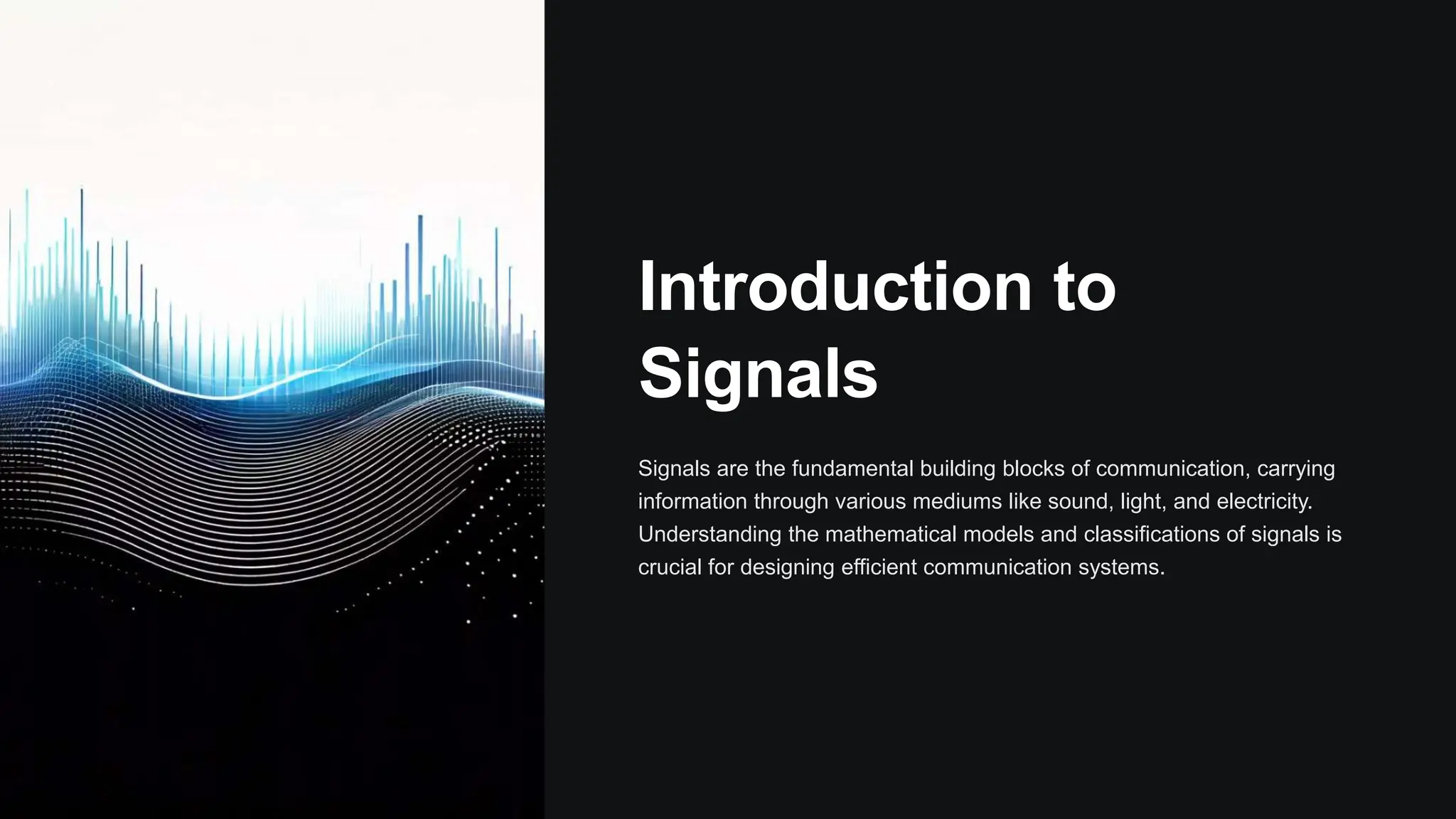
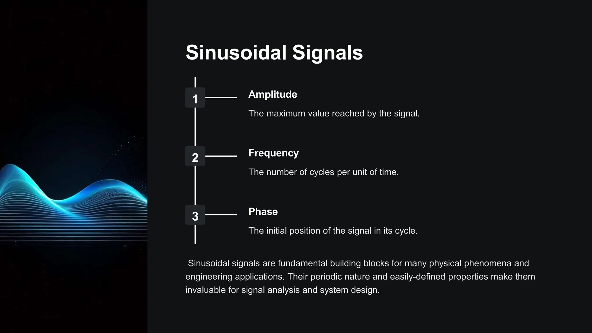
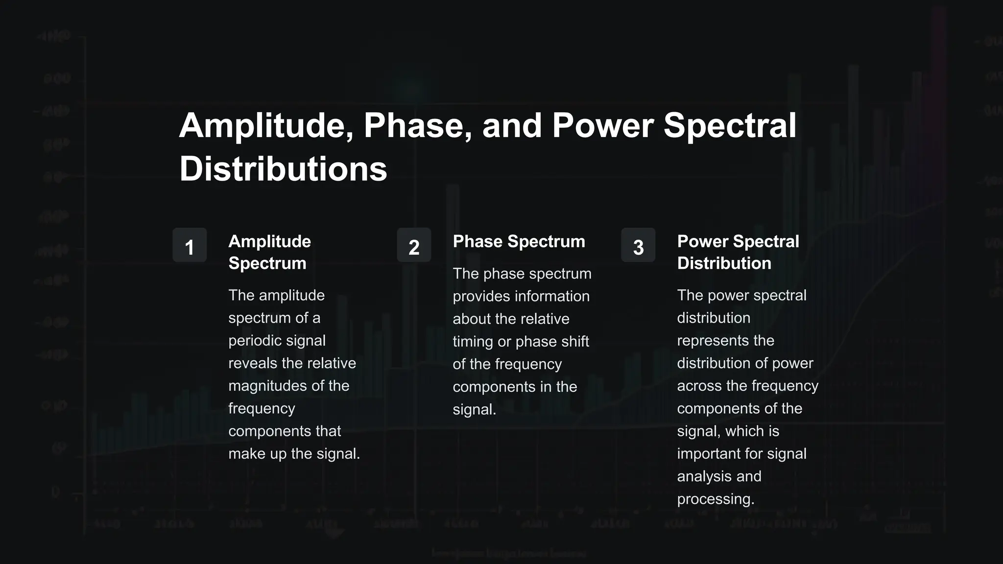
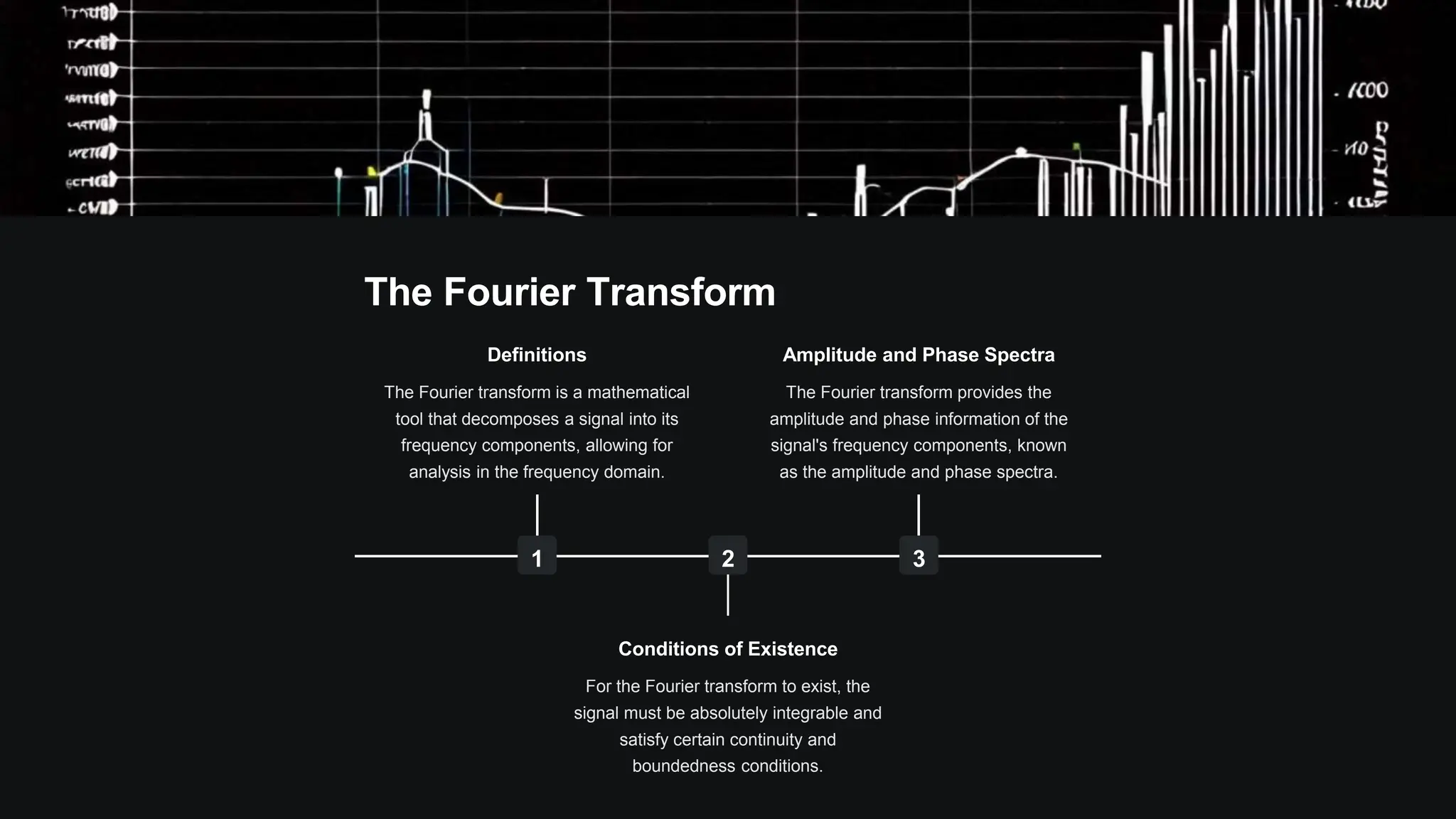
Introduction to
Signals
Signals are the fundamental building blocks of communication, carrying
information through various mediums like sound, light, and electricity.
Understanding the mathematical models and classifications of signals is
crucial for designing efficient communication systems.
Mathematical Model of Signals
1
Continuous-Time Signals
Signals that are defined for all points in
time, such as analog audio or video
waveforms.
2
Discrete-Time Signals
Signals that are defined only at specific,
equally-spaced time instants, such as
digital audio samples.
3
Signal Transformations
Applying mathematical operations like
Fourier transforms to analyze and
manipulate signals in the frequency
domain.
Signal Classification
Periodic vs. Aperiodic
Periodic signals repeat
themselves after a fixed
time interval, while
aperiodic signals do not.
Deterministic vs.
Random
Deterministic signals have
a known, predictable
behavior, while random
signals have
unpredictable, statistical
properties.
Energy vs. Power
Signals
Energy signals have a
finite amount of total
energy, while power
signals have a continuous
energy flow over time.
Elementary Signals in
Continuous Time
Continuous-time signals are functions that vary with time, like sound
waves or radio signals. Understanding the fundamental properties of
these signals is crucial for analyzing and processing them in engineering
applications.
Sinusoidal Signals
1 Amplitude
The maximum value reached by the signal.
2 Frequency
The number of cycles per unit of time.
3 Phase
The initial position of the signal in its cycle.
Sinusoidal signals are fundamental building blocks for many physical phenomena and
engineering applications. Their periodic nature and easily-defined properties make them
invaluable for signal analysis and system design.
Exponential Signals
Growth
Exponential signals can
model processes that
increase rapidly over time,
like population growth or
the spread of a disease.
Decay
They can also represent
phenomena that diminish
over time, such as the
discharge of a capacitor or
the absorption of light in a
medium.
Oscillation
Combining exponential
growth and decay creates
oscillating signals, which
are fundamental to many
electronic circuits and
communication systems.
Exponential signals are another important class of continuous-time functions, exhibiting either
growth or decay over time. They have wide-ranging applications in science, engineering, and
beyond.
Periodic Signals in
Continuous Time
Periodic signals in continuous time are mathematical functions that
repeat themselves at regular intervals. These signals are essential in
various fields, such as electronics, communications, and signal
processing, where they are used to transmit and process information.
by ECP-Ege
Fourier Series Representation
Trigonometric Form
Periodic signals can be
represented as a sum of
sine and cosine waves
with different amplitudes
and frequencies, known as
the Fourier series in
trigonometric form.
Harmonic Form
The Fourier series can
also be expressed in
harmonic form, where the
signal is represented as a
sum of harmonically
related sinusoids with
integer multiples of the
fundamental frequency.
Complex Form
The Fourier series can be
represented in complex
form, using complex
exponentials, which
provides a more concise
mathematical expression
and simplifies certain
calculations.
Amplitude, Phase, and Power Spectral
Distributions
1 Amplitude
Spectrum
The amplitude
spectrum of a
periodic signal
reveals the relative
magnitudes of the
frequency
components that
make up the signal.
2 Phase Spectrum
The phase spectrum
provides information
about the relative
timing or phase shift
of the frequency
components in the
signal.
3 Power Spectral
Distribution
The power spectral
distribution
represents the
distribution of power
across the frequency
components of the
signal, which is
important for signal
analysis and
processing.
Nonperiodic Signals
in Continuous Time
Nonperiodic signals in continuous time are not repeating patterns over
time. These signals do not have a well-defined period and can have a
wide range of irregular shapes and frequencies. Understanding the
characteristics of nonperiodic signals is crucial for analyzing and
processing real-world data.
The Fourier Transform
1
Definitions
The Fourier transform is a mathematical
tool that decomposes a signal into its
frequency components, allowing for
analysis in the frequency domain.
2
Conditions of Existence
For the Fourier transform to exist, the
signal must be absolutely integrable and
satisfy certain continuity and
boundedness conditions.
3
Amplitude and Phase Spectra
The Fourier transform provides the
amplitude and phase information of the
signal's frequency components, known
as the amplitude and phase spectra.
Spectral Energy Distribution
1 Aperiodic Signals
The spectral energy distribution of
an aperiodic signal is continuous
and often irregular, lacking the
distinct peaks associated with
periodic signals.
2 Energy Concentration
The spectral energy distribution
reveals how the signal's energy is
distributed across the frequency
spectrum, providing insights into the
signal's characteristics.
3 Frequency Analysis
Analyzing the spectral energy distribution can help identify dominant frequency
components and understand the underlying dynamics of the aperiodic signal.
Introduction to
Laplace Transform
The Laplace transform is a powerful mathematical tool used to analyze
and solve linear differential equations. It converts a function of time into a
function of a complex variable, enabling simpler analysis and solutions.
Definitions and Conditions of Existence
1 Definition
The Laplace
transform of a
function f(t) is
denoted as F(s),
where s is a complex
variable.
2 Conditions of
Existence
For the Laplace
transform to exist, the
function f(t) must be
piecewise continuous
and of exponential
order.
3 Exponential Order
This means that f(t)
must be bounded by
an exponential
function as t
approaches infinity.
Unilateral and Bilateral Laplace
Transforms
Unilateral Laplace
Transform
The unilateral Laplace
transform is defined for t ≥
0, and is commonly used
to analyze causal
systems.
Bilateral Laplace
Transform
The bilateral Laplace
transform is defined for all
real values of t, and is
used to analyze non-
causal systems.
Applications
Unilateral transforms are
used in control systems,
circuit analysis, and signal
processing, while bilateral
transforms are used in
quantum mechanics and
other fields.
Modulated Signals:
Amplitude Modulation
(AM)
Amplitude Modulation (AM) is a fundamental technique used in radio
communication to encode information onto a carrier wave. In an AM
signal, the amplitude of the carrier wave is varied in proportion to the
instantaneous value of the modulating signal.
Modulation Coefficients,
Spectral Content, and Useful
Band
The modulation coefficient determines the depth of amplitude modulation.
The AM signal's spectral content consists of the carrier frequency and two
sidebands, one above and one below the carrier. The useful band for an
AM signal is the total bandwidth occupied by the carrier and both
sidebands.
Effective Value of an AM Signal
1 Carrier Power
The effective value of
an AM signal
depends on the
carrier power, which
is reduced by the
modulation process.
2 Modulation Depth
The effective value
also depends on the
modulation depth,
which determines
how much the
amplitude fluctuates
around the carrier.
3 Sideband Power
The sidebands carry
the modulated
information and their
power contributes to
the overall effective
value.
Introduction to
Frequency Modulated
Signals
Frequency modulation (FM) is a method of encoding information in a
radio wave by varying the frequency of the carrier signal. This allows for
clearer audio quality and reduced interference compared to amplitude
modulation (AM) signals.
Principles of Frequency Modulation
1 Carrier Wave
The constant radio frequency that is modulated to carry the signal.
2 Modulating Signal
The audio or data that is encoded onto the carrier wave.
3 Frequency Deviation
The maximum change in frequency from the carrier wave caused by the
modulating signal.
Applications of FM Signals
Radio Broadcasting
FM signals are commonly
used for high-quality audio
broadcasts due to their
resistance to interference
and static.
Telecommunications
FM is used in two-way
radio systems, such as
those used by emergency
services and military
communications.
Telemetry
FM signals are employed
in telemetry applications to
transmit data from remote
sensors and instruments.
Passive Electric
Filters
Passive electric filters are electronic circuits that use only passive
components like resistors, capacitors, and inductors to selectively filter or
block certain frequencies while allowing others to pass. These filters find
applications in audio systems, power supplies, and various electronic
devices.
Constant K Filters
Design
Constant K filters are a
type of passive filter that
use a specific design
formula to determine the
component values. This
ensures a well-defined
frequency response and
makes them useful for
applications that require
precise filtering.
Applications
Constant K filters are
commonly used in
telephone systems, radio
frequency circuits, and
audio equipment to
remove unwanted signals
or frequencies.
Advantages
Their simple design,
predictable performance,
and relatively low cost
make constant K filters a
popular choice for many
filtering needs.
General Analysis of Constant K Filters
1 Frequency Response
Constant K filters exhibit a well-defined frequency response, with a sharp
cutoff at the desired cutoff frequency.
2 Impedance Matching
The filter design ensures that the input and output impedances are matched,
reducing signal reflections and maximizing power transfer.
3 Bandwidth Control
The filter parameters can be adjusted to control the bandwidth, allowing for
selective filtering of signals.
Constant K Filters: An
Introduction
Constant K filters are a fundamental type of analog electronic filter used
to control the frequency response of circuits. They offer a simple and
reliable way to create low-pass, high-pass, band-pass, and stop-band
filters for various applications.
Practical Filter Structures
Low-Pass
Low-pass filters allow low
frequencies to pass
through while attenuating
high frequencies. This is
useful for removing
unwanted high-frequency
noise.
High-Pass
High-pass filters do the
opposite, allowing high
frequencies to pass
through while blocking low
frequencies. This can be
used to remove unwanted
low-frequency
interference.
Band-Pass
Band-pass filters only
allow a specific range of
frequencies to pass
through, blocking both low
and high frequencies
outside this band.
Design and Implementation
Considerations
1 Component Selection
Choosing the right resistors,
capacitors, and inductors is crucial for
achieving the desired filter
characteristics.
2 Impedance Matching
Ensuring proper impedance matching
between filter stages is important for
minimizing reflections and signal loss.
3 Stability and Tolerances
Filter performance can be affected by
component tolerances and
environmental factors, requiring
careful design and testing.
4 Applications
Constant K filters find use in audio
processing, instrumentation,
communications, and many other
areas requiring frequency selectivity.
Active Filters:
Generalities
Active filters are electronic circuits that selectively allow or block certain
frequency components of a signal. They are widely used in audio,
communications, and control systems to shape the frequency response of
a system.
Voltage Transfer Functions
The voltage transfer function describes the relationship between the input
and output voltages of a filter. It is a mathematical expression that
captures the frequency-dependent behavior of the filter, allowing
engineers to analyze and design active filters with desired frequency
characteristics.
Simple Second-Order Active Filters
General Design
Second-order active filters
are constructed using op-
amps, resistors, and
capacitors. They provide a
more flexible frequency
response compared to
passive filters, allowing for
adjustable cutoff
frequencies and filter
slopes.
Key Parameters
Important design
parameters include the
cutoff frequency, filter type
(low-pass, high-pass,
band-pass, etc.), and
quality factor, which
determines the sharpness
of the frequency response.
Applications
Simple second-order
active filters find
widespread use in audio
processing, signal
conditioning, and control
systems, where precise
frequency shaping is
required.
Introduction to Active Filters
How Active Filters
Work
Active filters use amplifiers
to shape the frequency
response of a signal,
providing improved
performance compared to
passive filters.
Advantages of Active
Filters
Active filters offer
advantages like higher gain,
lower noise, and more
flexible design options
compared to passive filters.
Designing Active
Filters
Engineers can carefully
design active filters to
shape the frequency
response of a signal and
achieve the desired
performance.
Types of Active Filters
Low-Pass Filter
Allows low frequencies to
pass through while reducing
high frequencies, useful for
smoothing signals.
High-Pass Filter
Allows high frequencies to
pass through while blocking
low frequencies, useful for
removing DC offsets.
Band-Pass Filter
Allows a specific range of
frequencies to pass through
while blocking others, useful
for isolating signals.
Design Considerations and
Applications
1 Cutoff Frequency
The frequency at
which the filter's
response drops by
3dB, a key design
parameter.
2 Component
Selection
Choosing appropriate
resistors, capacitors,
and amplifiers to
achieve the desired
filter characteristics.
3 Applications
Active filters are used
in audio processing,
instrumentation,
control systems, and
more.
Active Filters with
Feedback Loops
Active filters are electronic circuits that use feedback loops to selectively
allow or block certain frequency ranges. These filters play a crucial role in
audio, communication, and signal processing applications, enabling
precise control over the frequency response of a system.
Feedback Loops in Active Filters
1
Input Signal
The input signal enters the filter circuit
and is processed through various
stages.
2
Amplification
The signal is amplified to the desired
level, ensuring sufficient gain for the
subsequent filtering stages.
3
Feedback Loop
The filtered output is fed back to the
input, creating a feedback loop that
enhances the filter's selectivity and
stability.
Low-Pass Active Filters
Concept
Low-pass active filters
allow low-frequency
signals to pass through
while blocking high-
frequency signals, creating
a smooth, filtered output.
Applications
These filters are
commonly used in audio
systems to remove
unwanted high-frequency
noise and in power
supplies to smooth out
ripple signals.
Structures
Common low-pass active
filter structures include the
Sallen-Key and Multiple
Feedback (MFB)
topologies.
High-Pass Active Filters
1 Concept
High-pass active
filters allow high-
frequency signals to
pass through while
blocking low-
frequency signals,
creating a sharp,
filtered output.
2 Applications
These filters are used
in audio systems to
remove unwanted
low-frequency noise,
such as rumble or
hum, and in
communication
systems to remove
DC offsets.
3 Structures
Common high-pass
active filter structures
include the Sallen-
Key and Multiple
Feedback (MFB)
topologies, similar to
low-pass filters.
Band-Pass Active Filters
Concept
Band-pass active filters allow a specific
range of frequencies to pass through
while blocking both low and high
frequencies, creating a selective
output.
Applications
These filters are used in audio systems
to isolate specific frequency bands,
such as for tone control, and in
communication systems to extract
narrowband signals from a wider
frequency range.
Structures
Common band-pass active filter structures include the State Variable and Multiple
Feedback (MFB) topologies, which provide independent control over the center
frequency and bandwidth.
Band-Stop Active Filters
Narrow Bandwidth
Band-stop active filters
have a narrow frequency
range that is blocked,
allowing all other
frequencies to pass
through.
Selective Rejection
These filters are used to
remove specific unwanted
frequency components,
such as power line hum or
other narrowband
interference.
Flexible Design
Band-stop active filters can
be designed using various
topologies, including the
State Variable and Multiple
Feedback (MFB)
configurations.
Ege Alp Kuleli
Erasmus Student
Electrical Electronics Engineering
Oradea Univertisty

Signals Processing power point detailed presentation

  • 1.
    Introduction to Signals Signals arethe fundamental building blocks of communication, carrying information through various mediums like sound, light, and electricity. Understanding the mathematical models and classifications of signals is crucial for designing efficient communication systems.
  • 2.
    Mathematical Model ofSignals 1 Continuous-Time Signals Signals that are defined for all points in time, such as analog audio or video waveforms. 2 Discrete-Time Signals Signals that are defined only at specific, equally-spaced time instants, such as digital audio samples. 3 Signal Transformations Applying mathematical operations like Fourier transforms to analyze and manipulate signals in the frequency domain.
  • 3.
    Signal Classification Periodic vs.Aperiodic Periodic signals repeat themselves after a fixed time interval, while aperiodic signals do not. Deterministic vs. Random Deterministic signals have a known, predictable behavior, while random signals have unpredictable, statistical properties. Energy vs. Power Signals Energy signals have a finite amount of total energy, while power signals have a continuous energy flow over time.
  • 4.
    Elementary Signals in ContinuousTime Continuous-time signals are functions that vary with time, like sound waves or radio signals. Understanding the fundamental properties of these signals is crucial for analyzing and processing them in engineering applications.
  • 5.
    Sinusoidal Signals 1 Amplitude Themaximum value reached by the signal. 2 Frequency The number of cycles per unit of time. 3 Phase The initial position of the signal in its cycle. Sinusoidal signals are fundamental building blocks for many physical phenomena and engineering applications. Their periodic nature and easily-defined properties make them invaluable for signal analysis and system design.
  • 6.
    Exponential Signals Growth Exponential signalscan model processes that increase rapidly over time, like population growth or the spread of a disease. Decay They can also represent phenomena that diminish over time, such as the discharge of a capacitor or the absorption of light in a medium. Oscillation Combining exponential growth and decay creates oscillating signals, which are fundamental to many electronic circuits and communication systems. Exponential signals are another important class of continuous-time functions, exhibiting either growth or decay over time. They have wide-ranging applications in science, engineering, and beyond.
  • 7.
    Periodic Signals in ContinuousTime Periodic signals in continuous time are mathematical functions that repeat themselves at regular intervals. These signals are essential in various fields, such as electronics, communications, and signal processing, where they are used to transmit and process information. by ECP-Ege
  • 8.
    Fourier Series Representation TrigonometricForm Periodic signals can be represented as a sum of sine and cosine waves with different amplitudes and frequencies, known as the Fourier series in trigonometric form. Harmonic Form The Fourier series can also be expressed in harmonic form, where the signal is represented as a sum of harmonically related sinusoids with integer multiples of the fundamental frequency. Complex Form The Fourier series can be represented in complex form, using complex exponentials, which provides a more concise mathematical expression and simplifies certain calculations.
  • 9.
    Amplitude, Phase, andPower Spectral Distributions 1 Amplitude Spectrum The amplitude spectrum of a periodic signal reveals the relative magnitudes of the frequency components that make up the signal. 2 Phase Spectrum The phase spectrum provides information about the relative timing or phase shift of the frequency components in the signal. 3 Power Spectral Distribution The power spectral distribution represents the distribution of power across the frequency components of the signal, which is important for signal analysis and processing.
  • 10.
    Nonperiodic Signals in ContinuousTime Nonperiodic signals in continuous time are not repeating patterns over time. These signals do not have a well-defined period and can have a wide range of irregular shapes and frequencies. Understanding the characteristics of nonperiodic signals is crucial for analyzing and processing real-world data.
  • 11.
    The Fourier Transform 1 Definitions TheFourier transform is a mathematical tool that decomposes a signal into its frequency components, allowing for analysis in the frequency domain. 2 Conditions of Existence For the Fourier transform to exist, the signal must be absolutely integrable and satisfy certain continuity and boundedness conditions. 3 Amplitude and Phase Spectra The Fourier transform provides the amplitude and phase information of the signal's frequency components, known as the amplitude and phase spectra.
  • 12.
    Spectral Energy Distribution 1Aperiodic Signals The spectral energy distribution of an aperiodic signal is continuous and often irregular, lacking the distinct peaks associated with periodic signals. 2 Energy Concentration The spectral energy distribution reveals how the signal's energy is distributed across the frequency spectrum, providing insights into the signal's characteristics. 3 Frequency Analysis Analyzing the spectral energy distribution can help identify dominant frequency components and understand the underlying dynamics of the aperiodic signal.
  • 13.
    Introduction to Laplace Transform TheLaplace transform is a powerful mathematical tool used to analyze and solve linear differential equations. It converts a function of time into a function of a complex variable, enabling simpler analysis and solutions.
  • 14.
    Definitions and Conditionsof Existence 1 Definition The Laplace transform of a function f(t) is denoted as F(s), where s is a complex variable. 2 Conditions of Existence For the Laplace transform to exist, the function f(t) must be piecewise continuous and of exponential order. 3 Exponential Order This means that f(t) must be bounded by an exponential function as t approaches infinity.
  • 15.
    Unilateral and BilateralLaplace Transforms Unilateral Laplace Transform The unilateral Laplace transform is defined for t ≥ 0, and is commonly used to analyze causal systems. Bilateral Laplace Transform The bilateral Laplace transform is defined for all real values of t, and is used to analyze non- causal systems. Applications Unilateral transforms are used in control systems, circuit analysis, and signal processing, while bilateral transforms are used in quantum mechanics and other fields.
  • 16.
    Modulated Signals: Amplitude Modulation (AM) AmplitudeModulation (AM) is a fundamental technique used in radio communication to encode information onto a carrier wave. In an AM signal, the amplitude of the carrier wave is varied in proportion to the instantaneous value of the modulating signal.
  • 17.
    Modulation Coefficients, Spectral Content,and Useful Band The modulation coefficient determines the depth of amplitude modulation. The AM signal's spectral content consists of the carrier frequency and two sidebands, one above and one below the carrier. The useful band for an AM signal is the total bandwidth occupied by the carrier and both sidebands.
  • 18.
    Effective Value ofan AM Signal 1 Carrier Power The effective value of an AM signal depends on the carrier power, which is reduced by the modulation process. 2 Modulation Depth The effective value also depends on the modulation depth, which determines how much the amplitude fluctuates around the carrier. 3 Sideband Power The sidebands carry the modulated information and their power contributes to the overall effective value.
  • 19.
    Introduction to Frequency Modulated Signals Frequencymodulation (FM) is a method of encoding information in a radio wave by varying the frequency of the carrier signal. This allows for clearer audio quality and reduced interference compared to amplitude modulation (AM) signals.
  • 20.
    Principles of FrequencyModulation 1 Carrier Wave The constant radio frequency that is modulated to carry the signal. 2 Modulating Signal The audio or data that is encoded onto the carrier wave. 3 Frequency Deviation The maximum change in frequency from the carrier wave caused by the modulating signal.
  • 21.
    Applications of FMSignals Radio Broadcasting FM signals are commonly used for high-quality audio broadcasts due to their resistance to interference and static. Telecommunications FM is used in two-way radio systems, such as those used by emergency services and military communications. Telemetry FM signals are employed in telemetry applications to transmit data from remote sensors and instruments.
  • 22.
    Passive Electric Filters Passive electricfilters are electronic circuits that use only passive components like resistors, capacitors, and inductors to selectively filter or block certain frequencies while allowing others to pass. These filters find applications in audio systems, power supplies, and various electronic devices.
  • 23.
    Constant K Filters Design ConstantK filters are a type of passive filter that use a specific design formula to determine the component values. This ensures a well-defined frequency response and makes them useful for applications that require precise filtering. Applications Constant K filters are commonly used in telephone systems, radio frequency circuits, and audio equipment to remove unwanted signals or frequencies. Advantages Their simple design, predictable performance, and relatively low cost make constant K filters a popular choice for many filtering needs.
  • 24.
    General Analysis ofConstant K Filters 1 Frequency Response Constant K filters exhibit a well-defined frequency response, with a sharp cutoff at the desired cutoff frequency. 2 Impedance Matching The filter design ensures that the input and output impedances are matched, reducing signal reflections and maximizing power transfer. 3 Bandwidth Control The filter parameters can be adjusted to control the bandwidth, allowing for selective filtering of signals.
  • 25.
    Constant K Filters:An Introduction Constant K filters are a fundamental type of analog electronic filter used to control the frequency response of circuits. They offer a simple and reliable way to create low-pass, high-pass, band-pass, and stop-band filters for various applications.
  • 26.
    Practical Filter Structures Low-Pass Low-passfilters allow low frequencies to pass through while attenuating high frequencies. This is useful for removing unwanted high-frequency noise. High-Pass High-pass filters do the opposite, allowing high frequencies to pass through while blocking low frequencies. This can be used to remove unwanted low-frequency interference. Band-Pass Band-pass filters only allow a specific range of frequencies to pass through, blocking both low and high frequencies outside this band.
  • 27.
    Design and Implementation Considerations 1Component Selection Choosing the right resistors, capacitors, and inductors is crucial for achieving the desired filter characteristics. 2 Impedance Matching Ensuring proper impedance matching between filter stages is important for minimizing reflections and signal loss. 3 Stability and Tolerances Filter performance can be affected by component tolerances and environmental factors, requiring careful design and testing. 4 Applications Constant K filters find use in audio processing, instrumentation, communications, and many other areas requiring frequency selectivity.
  • 28.
    Active Filters: Generalities Active filtersare electronic circuits that selectively allow or block certain frequency components of a signal. They are widely used in audio, communications, and control systems to shape the frequency response of a system.
  • 29.
    Voltage Transfer Functions Thevoltage transfer function describes the relationship between the input and output voltages of a filter. It is a mathematical expression that captures the frequency-dependent behavior of the filter, allowing engineers to analyze and design active filters with desired frequency characteristics.
  • 30.
    Simple Second-Order ActiveFilters General Design Second-order active filters are constructed using op- amps, resistors, and capacitors. They provide a more flexible frequency response compared to passive filters, allowing for adjustable cutoff frequencies and filter slopes. Key Parameters Important design parameters include the cutoff frequency, filter type (low-pass, high-pass, band-pass, etc.), and quality factor, which determines the sharpness of the frequency response. Applications Simple second-order active filters find widespread use in audio processing, signal conditioning, and control systems, where precise frequency shaping is required.
  • 31.
    Introduction to ActiveFilters How Active Filters Work Active filters use amplifiers to shape the frequency response of a signal, providing improved performance compared to passive filters. Advantages of Active Filters Active filters offer advantages like higher gain, lower noise, and more flexible design options compared to passive filters. Designing Active Filters Engineers can carefully design active filters to shape the frequency response of a signal and achieve the desired performance.
  • 32.
    Types of ActiveFilters Low-Pass Filter Allows low frequencies to pass through while reducing high frequencies, useful for smoothing signals. High-Pass Filter Allows high frequencies to pass through while blocking low frequencies, useful for removing DC offsets. Band-Pass Filter Allows a specific range of frequencies to pass through while blocking others, useful for isolating signals.
  • 33.
    Design Considerations and Applications 1Cutoff Frequency The frequency at which the filter's response drops by 3dB, a key design parameter. 2 Component Selection Choosing appropriate resistors, capacitors, and amplifiers to achieve the desired filter characteristics. 3 Applications Active filters are used in audio processing, instrumentation, control systems, and more.
  • 34.
    Active Filters with FeedbackLoops Active filters are electronic circuits that use feedback loops to selectively allow or block certain frequency ranges. These filters play a crucial role in audio, communication, and signal processing applications, enabling precise control over the frequency response of a system.
  • 35.
    Feedback Loops inActive Filters 1 Input Signal The input signal enters the filter circuit and is processed through various stages. 2 Amplification The signal is amplified to the desired level, ensuring sufficient gain for the subsequent filtering stages. 3 Feedback Loop The filtered output is fed back to the input, creating a feedback loop that enhances the filter's selectivity and stability.
  • 36.
    Low-Pass Active Filters Concept Low-passactive filters allow low-frequency signals to pass through while blocking high- frequency signals, creating a smooth, filtered output. Applications These filters are commonly used in audio systems to remove unwanted high-frequency noise and in power supplies to smooth out ripple signals. Structures Common low-pass active filter structures include the Sallen-Key and Multiple Feedback (MFB) topologies.
  • 37.
    High-Pass Active Filters 1Concept High-pass active filters allow high- frequency signals to pass through while blocking low- frequency signals, creating a sharp, filtered output. 2 Applications These filters are used in audio systems to remove unwanted low-frequency noise, such as rumble or hum, and in communication systems to remove DC offsets. 3 Structures Common high-pass active filter structures include the Sallen- Key and Multiple Feedback (MFB) topologies, similar to low-pass filters.
  • 38.
    Band-Pass Active Filters Concept Band-passactive filters allow a specific range of frequencies to pass through while blocking both low and high frequencies, creating a selective output. Applications These filters are used in audio systems to isolate specific frequency bands, such as for tone control, and in communication systems to extract narrowband signals from a wider frequency range. Structures Common band-pass active filter structures include the State Variable and Multiple Feedback (MFB) topologies, which provide independent control over the center frequency and bandwidth.
  • 39.
    Band-Stop Active Filters NarrowBandwidth Band-stop active filters have a narrow frequency range that is blocked, allowing all other frequencies to pass through. Selective Rejection These filters are used to remove specific unwanted frequency components, such as power line hum or other narrowband interference. Flexible Design Band-stop active filters can be designed using various topologies, including the State Variable and Multiple Feedback (MFB) configurations.
  • 40.
    Ege Alp Kuleli ErasmusStudent Electrical Electronics Engineering Oradea Univertisty