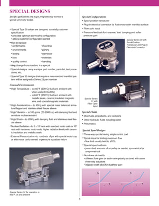
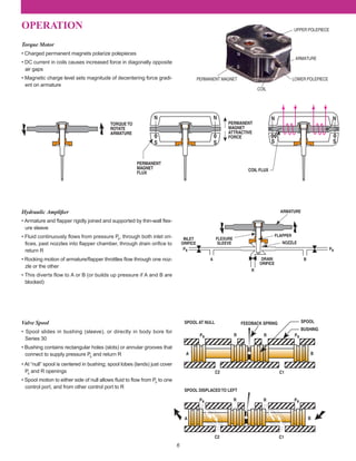
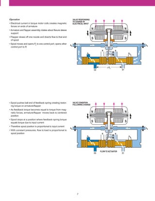
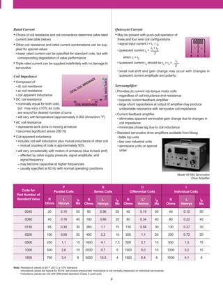
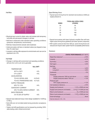
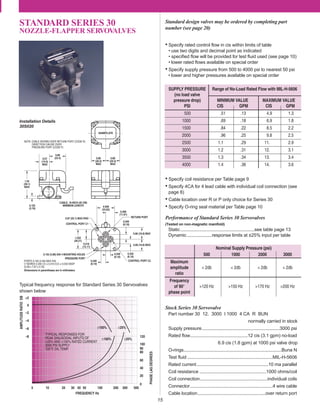
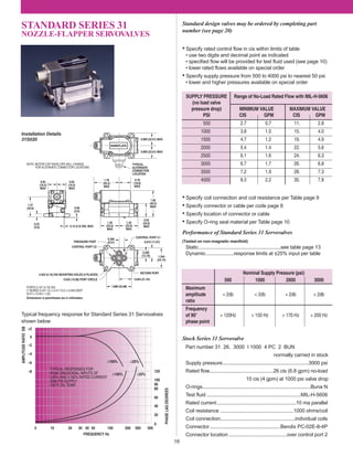
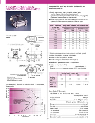
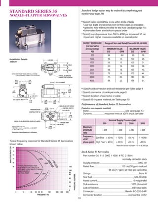
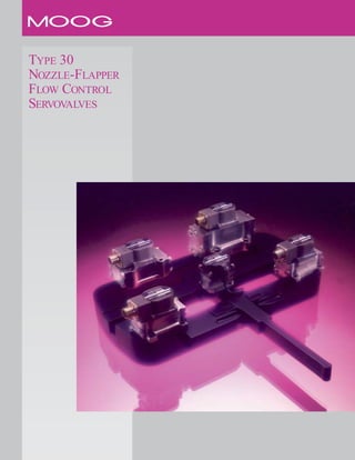
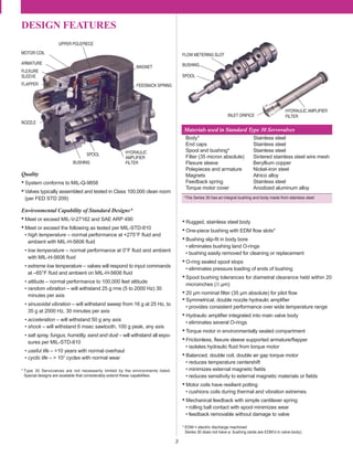
The document describes Type 30 nozzle-flapper servovalves. It summarizes:
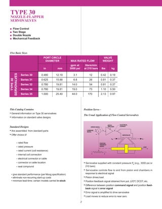
1) Five basic sizes of Type 30 servovalves with flow ratings ranging from 0.48 to 1 gpm or 12.19 to 25.4 liters/min at 3000 psi or 210 bars.
2) Standard designs offer choices for rated flow, pressure, coil configuration and include standard performance and minimize costs and lead times.
3) Servovalves typically control flow to actuator ports in response to an electrical command signal to move a load based on position feedback.

![4
TERMINOLOGY
Units
Recommended English and Metric
units for expressing servovalve per-
formance include the following:
Electrical
Input Current - The electrical current to the valve which commands con-
trol flow, expressed in milliamperes (ma).
Rated Current - The specified input of either polarity to produce rated
flow, expressed in milliamperes (ma). Rated current is specified for a par-
ticular coil configuration (differential, series, individual or parallel coils)
and does not include null bias current.
Quiescent Current - A dc current that is present in each valve coil when
using a differential coil connection. The polarity of the current in the two
coils is reversed so that no net signal input exists.
Coil Impedance - The complex ratio of coil voltage to coil current. Coil
impedance will vary with signal frequency, amplitude, and other operat-
ing conditions, but can be approximated by the dc coil resistance (R ohms)
and the apparent coil inductance (L henrys) measured at a signal fre-
quency.
Dither - An ac signal sometimes superimposed on the servovalve input
to improve system resolution. Dither is expressed by the dither frequen-
cy (Hz) and the peak-to-peak dither current amplitude (ma).
Hydraulic
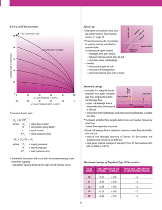
Control Flow QV
- The flow through the valve control ports to the load
expressed in in3/sec (cis), gal/min (gpm), liters/min (lpm) or for fuel appli-
cations lbs/hr (pph).
Rated Flow QR
- The specified control flow corresponding to rated cur-
rent and given supply and load pressure conditions. Rated flow is nor-
mally specified as the no-load flow and is expressed in cis, gpm, lpm
or pph.
Flow Gain - The nominal relationship of control flow to input current,
expressed as cis/ma, gpm/ma, lpm/ma or pph/ma.
No Load Flow - The control flow with zero load pressure drop, expressed
in cis, gpm, lpm or pph.
Internal Leakage - The total internal valve flow from pressure to return
with zero control flow (usually measured with control ports blocked),
expressed in cis, gpm, lpm or pph. Leakage flow will vary with input cur-
rent, generally being a maximum at the valve null (called null leakage).
Load Pressure Drop ∆PL
- The differential pressure between the control
ports (that is, across the load actuator), expressed in lbs/in2 (psi), or bars.
Valve Pressure Drop ∆PV
- The sum of the differential pressures across
the control orifices of the servovalve spool, expressed in psi or bars. Valve
pressure drop will equal the supply pressure, minus the return pressure,
minus the load pressure drop.[∆PV
= (PS
–R) – ∆PL
]
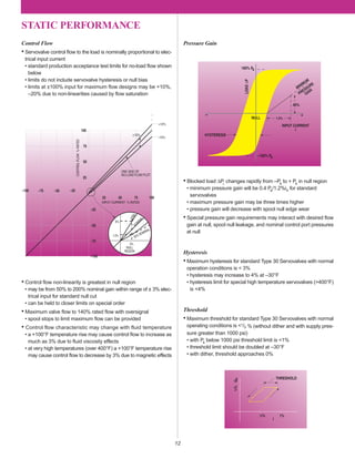
Performance
Linearity - The maximum deviation of control flow from the best straight
line of flow gain. Expressed as percent of rated current.
Symmetry - The degree of equality between the flow gain of one polar-
ity and that of reversed polarity, measured as the difference in flow gain
for each polarity and expressed as percent of the greater.
Hysteresis - The difference in valve input currents required to produce
the same valve output as the valve is slowly cycled between plus and
minus rated current. Expressed as percent of rated current.
Threshold - The increment of input current required to produce a change
in valve output. Valve threshold is usually measured as the current incre-
ment required to change from an increasing output to a decreasing out-
put. Expressed as percent of rated current.
Lap - In a sliding spool valve, the relative axial position relationship between
the fixed and movable flow-metering edges with the spool at null. Lap is
measured as the total separation at zero flow of straight line extensions
of the nearly straight portions of the flow curve, drawn separately for each
polarity. Expressed as percent of rated current.
Pressure Gain - The change of load pressure drop with input current
and zero control flow (control ports blocked). Expressed as nominal psi/ma
or bars/ma throughout the range of load pressure between ±40% supply
pressure.
Null - The condition where the valve supplies zero control flow at zero
load pressure drop.
Null Bias - The input current required to bring the valve to null, exclud-
ing the effects of valve hysteresis. Expressed as percent of rated current.
Null Shift - The change in null bias resulting from changes in operating
conditions or environment. Expressed as percent of rated current.
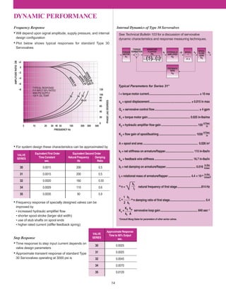
Frequency Response - The relationship of no-load control flow to input
current when the current is made to vary sinusoidally at constant ampli-
tude over a range of frequencies. Frequency response is expressed by
the amplitude ratio (in decibels), and phase angle (in degrees), over a
specific frequency range.
Per SAE ARP 490
See Moog Technical Bulletin No. 117 for a complete discussion of servo-
valve terminology and test techniques.
*JP-4 and JP-5 jet fuel
English Metric Conversion
in3/sec (cis) Liters/min (lpm) 0.98 lpm/cis
Fluid Flow 100.1 pph/cis*
gal/min (gpm) 3.78 lpm/gpm
Fluid Pressure lb/in2 (psi) bars 0.069 bars/psi
Dimensions inches (in)
millimeters (mm) 25.4 mm/in
micrometers (µm) 25400µm/in
Weight pounds (lb) kilograms (kg) 0.454 kg/lb
Force pounds (lb) Newtons (N) 4.45 N/lb
Torque in-lb Newton meters (N-m) 0.113 N-m/in-lb
Temperature degrees Fahrenheit (°F) degrees Celsius (°C) °C=5/9 (°F–32)](https://image.slidesharecdn.com/moog30seriescatalogtonight-160225154559/85/Moog-30-series-catalog-tonight-4-320.jpg)