Download to read offline

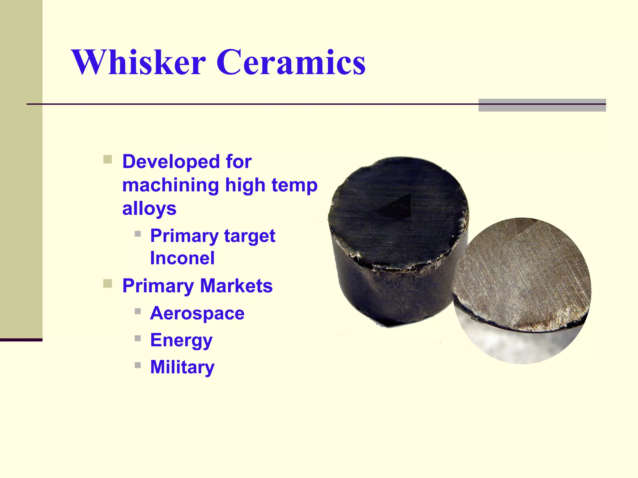
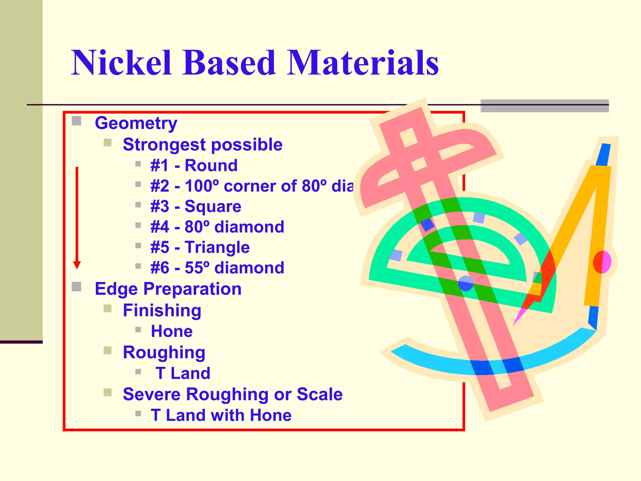
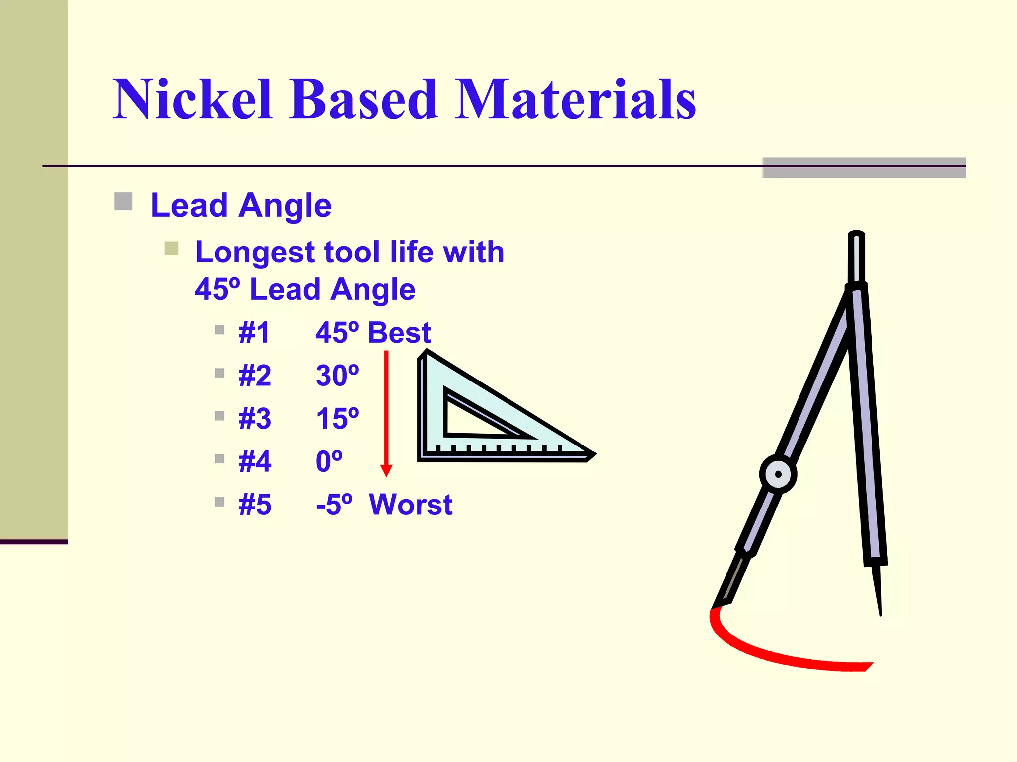
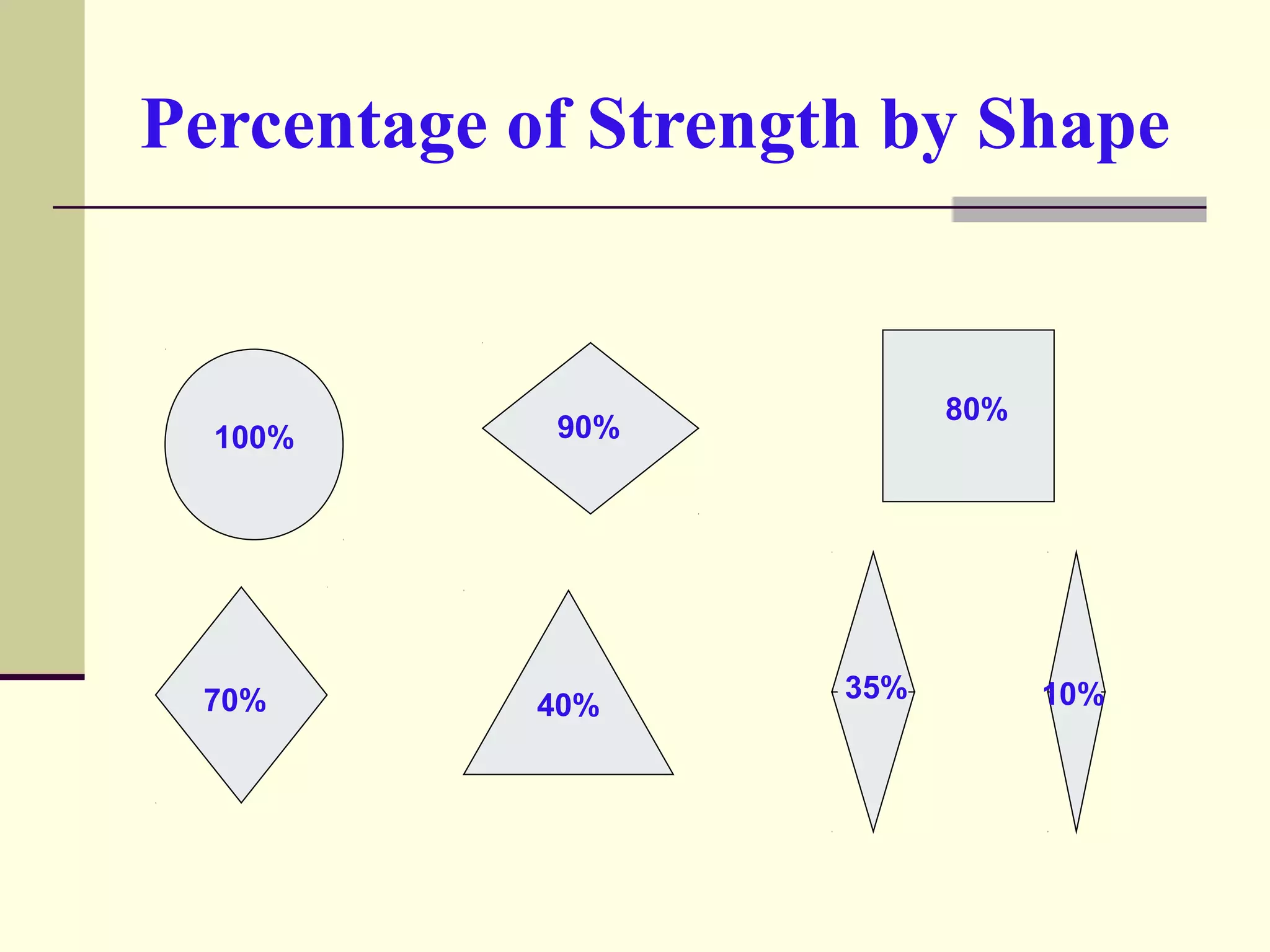
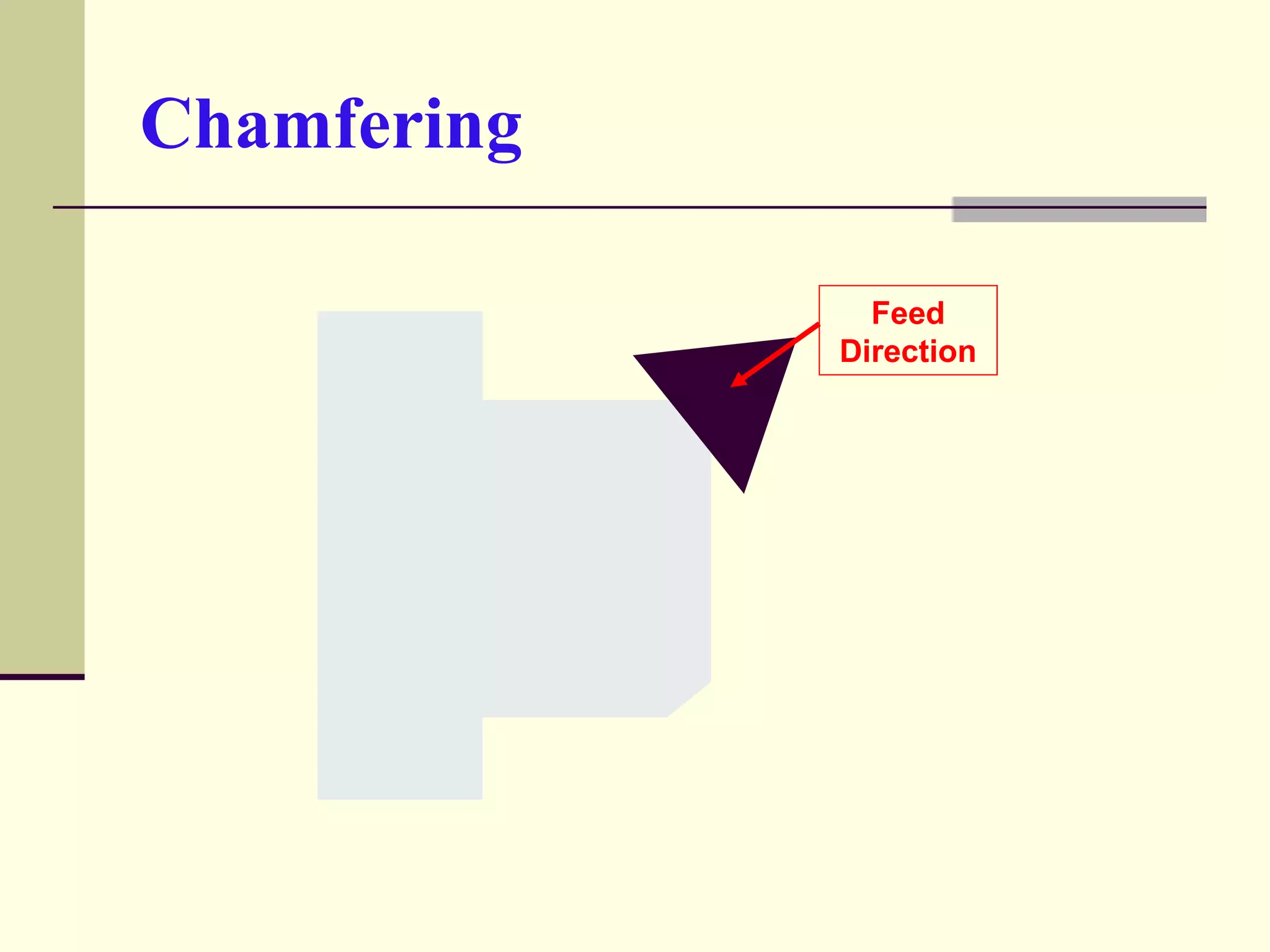
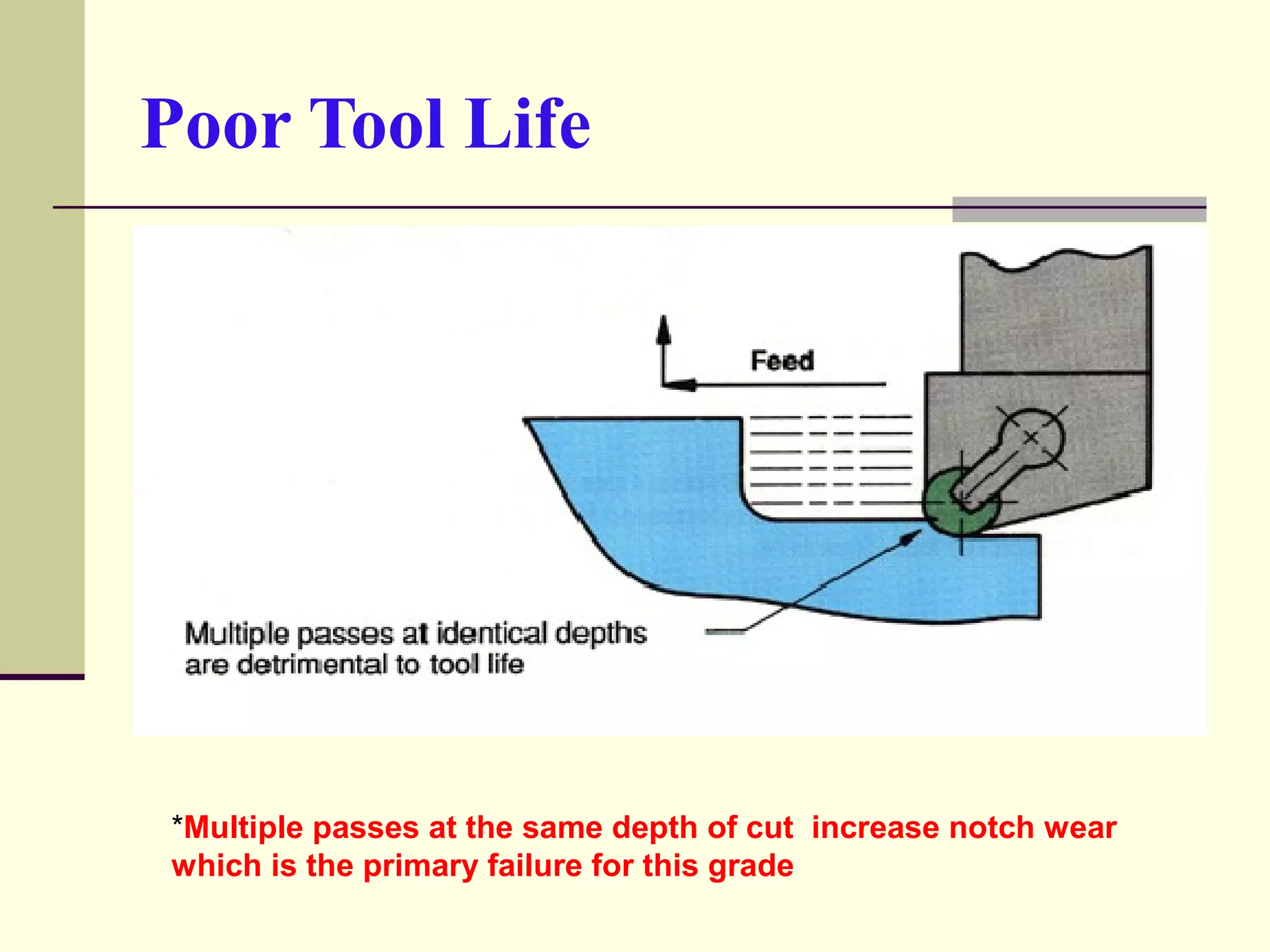
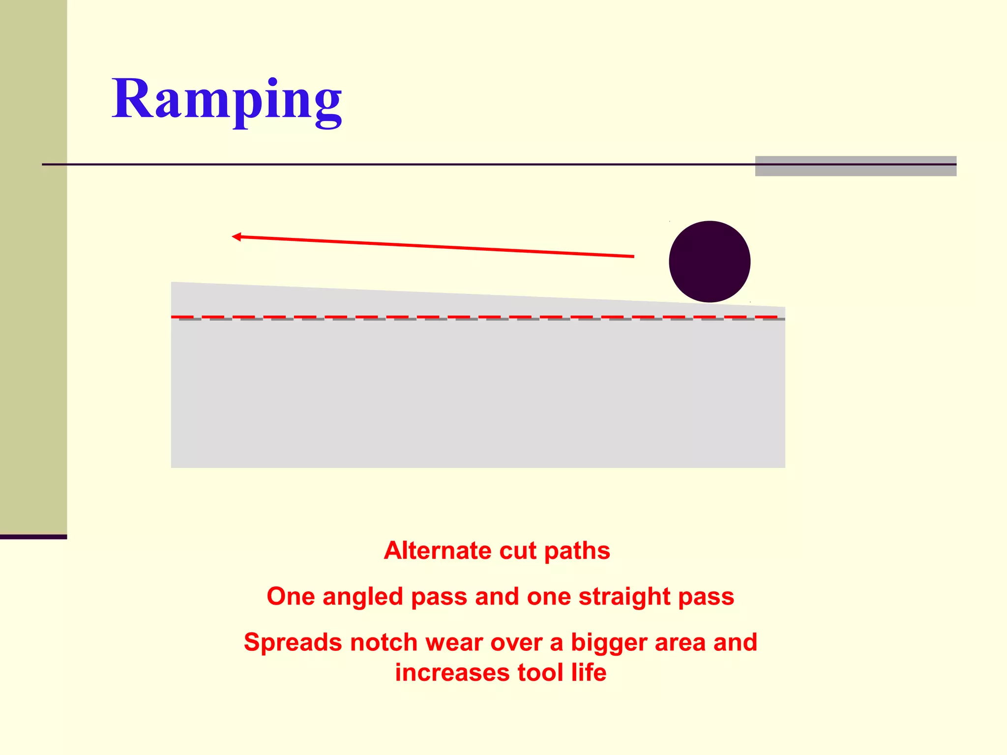
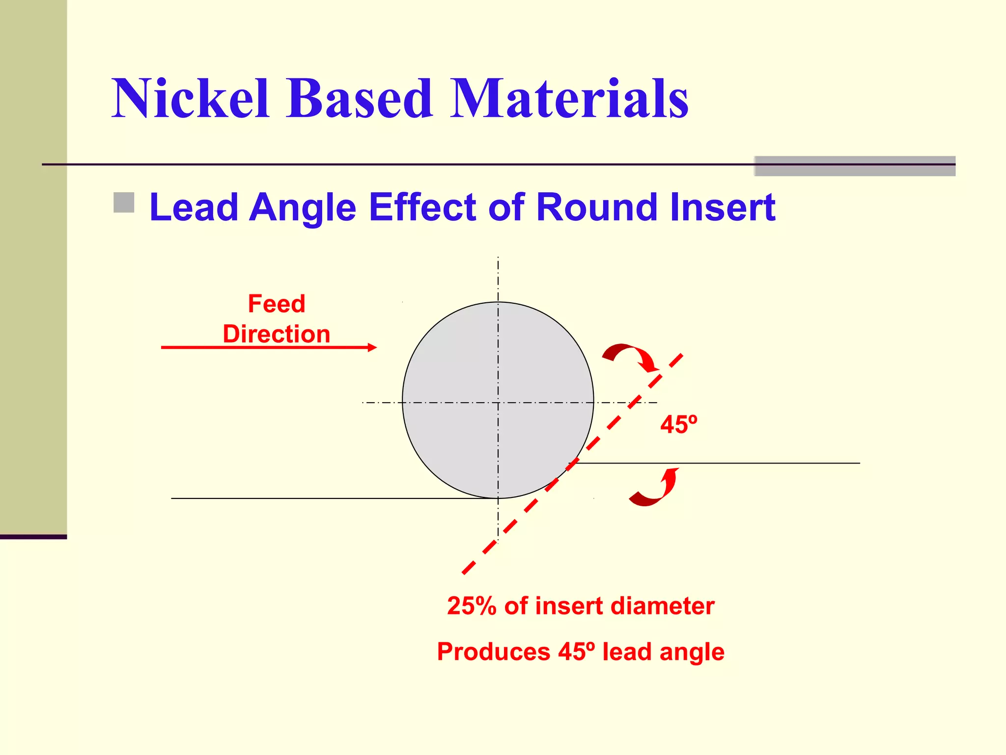
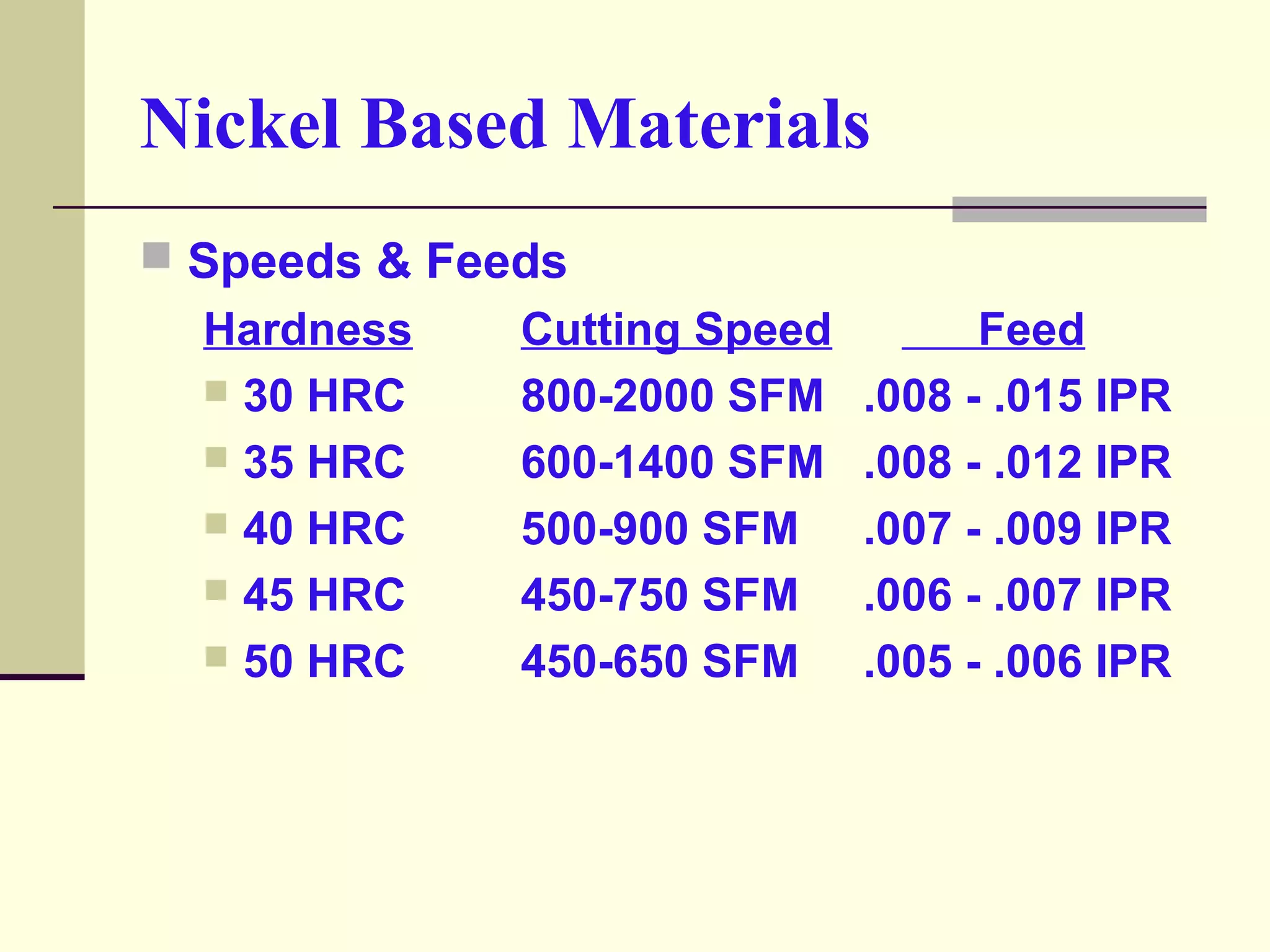
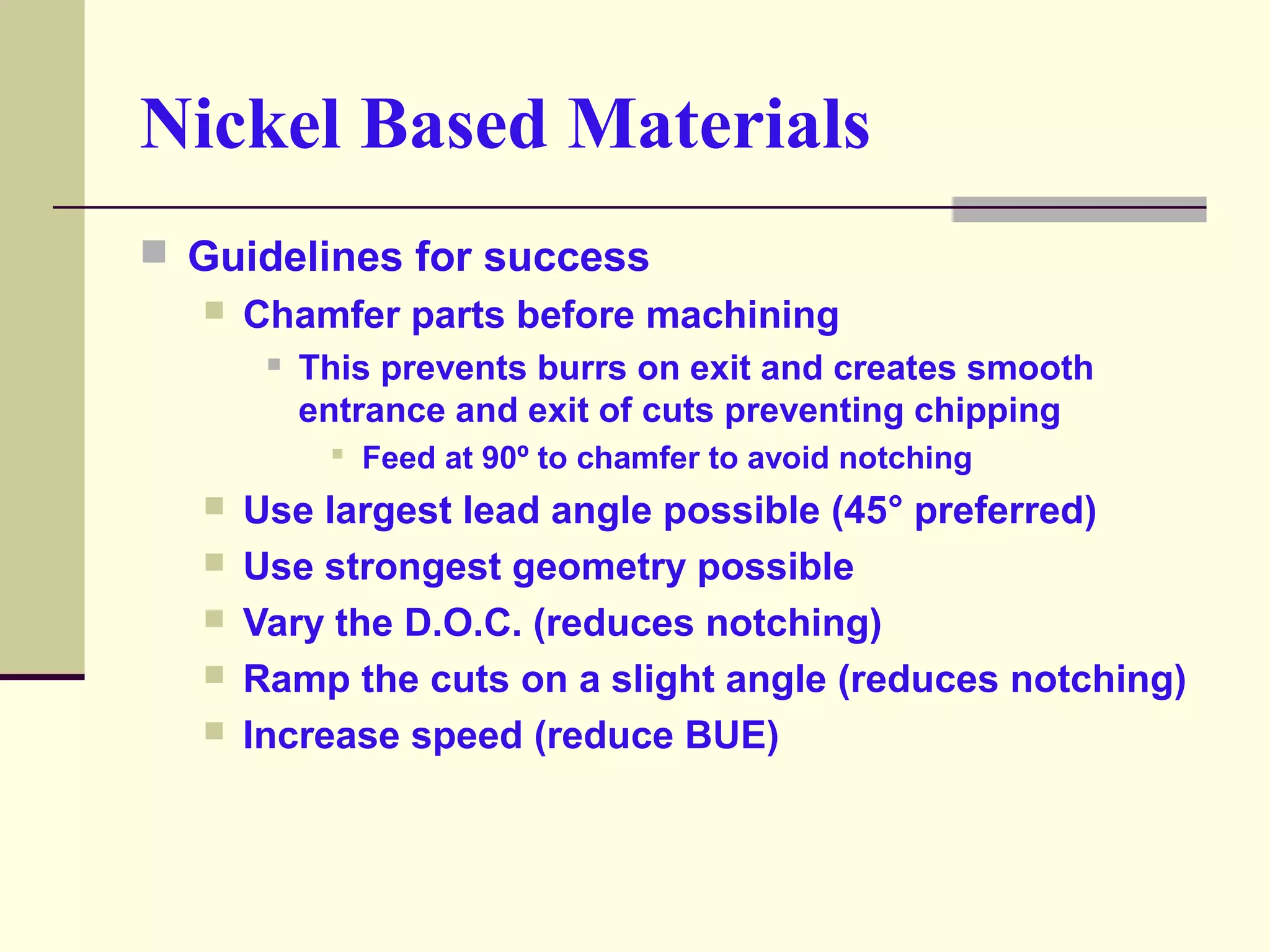
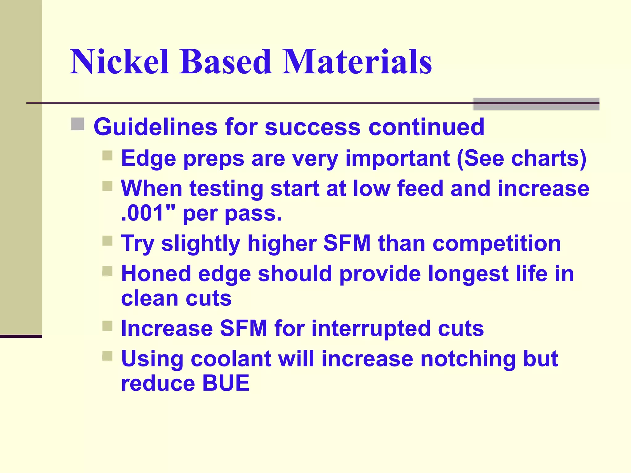
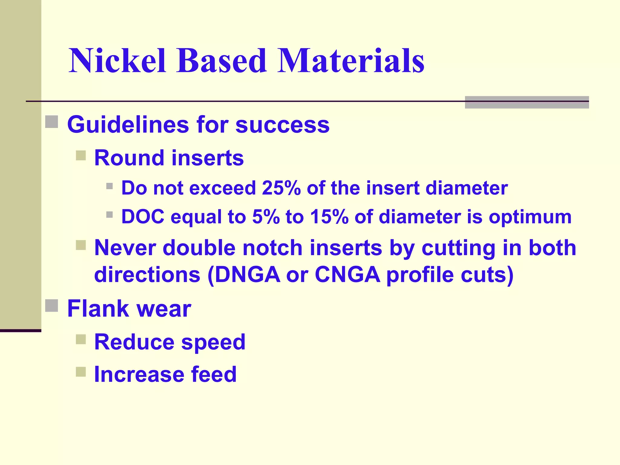
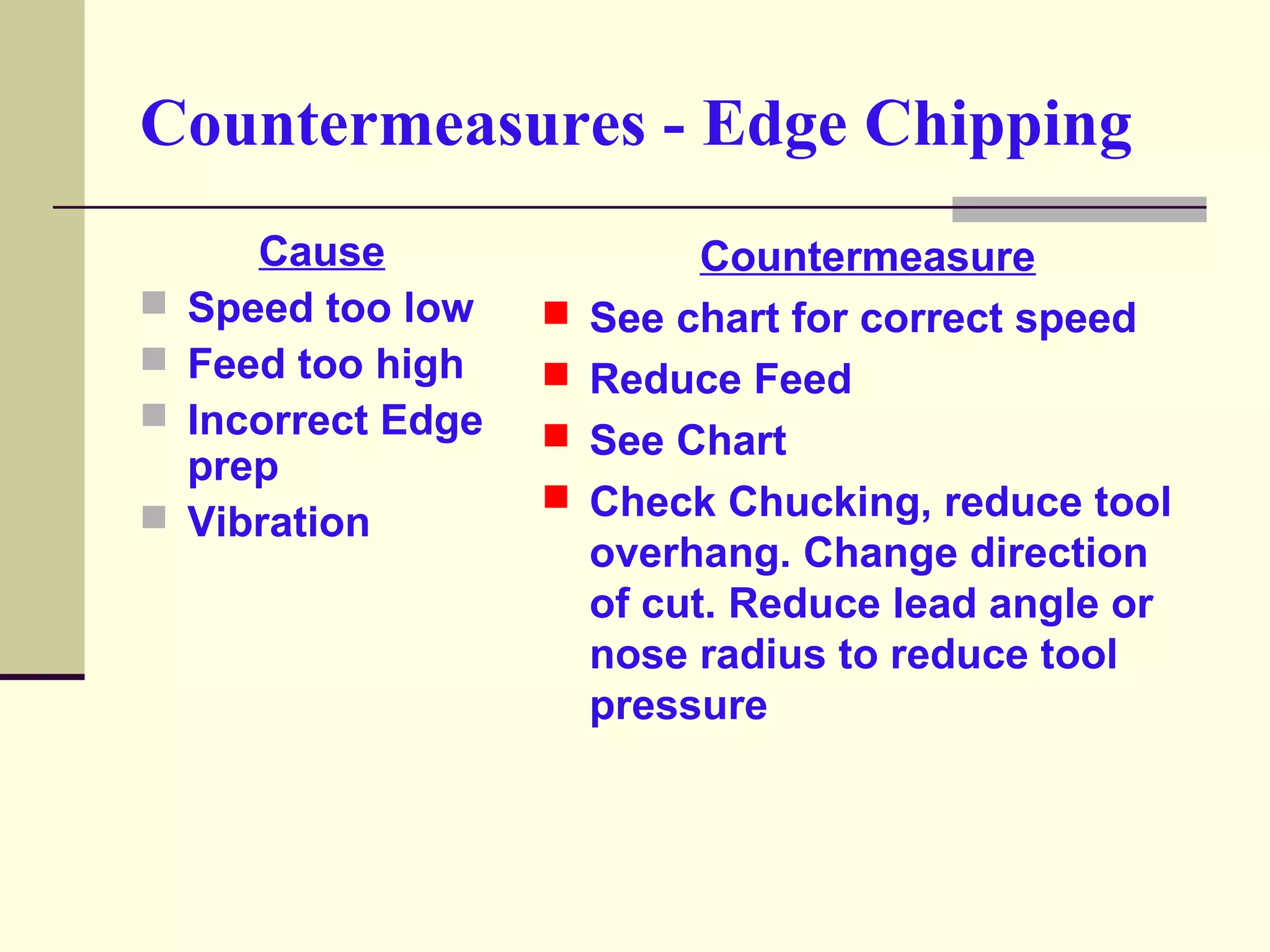
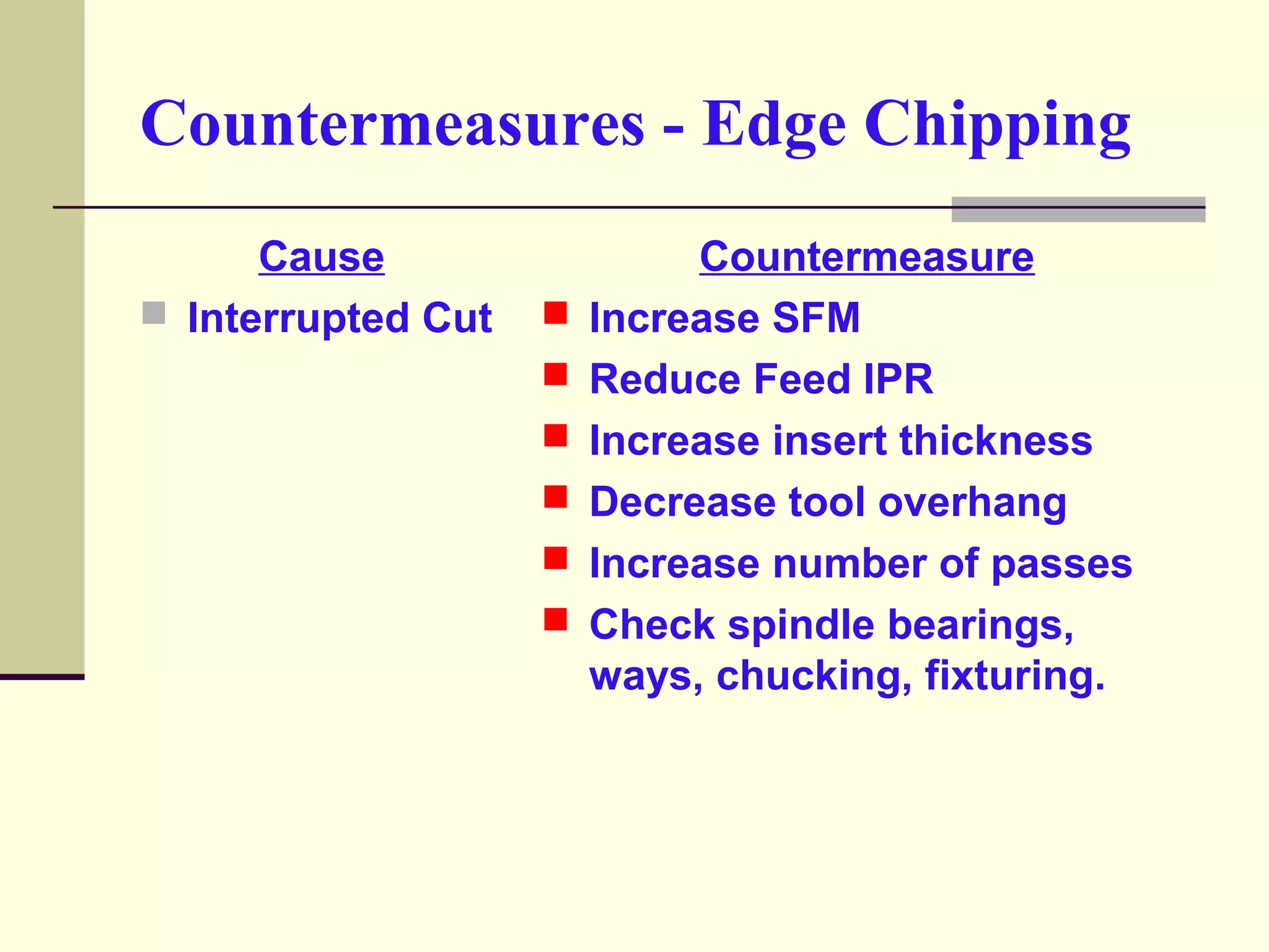

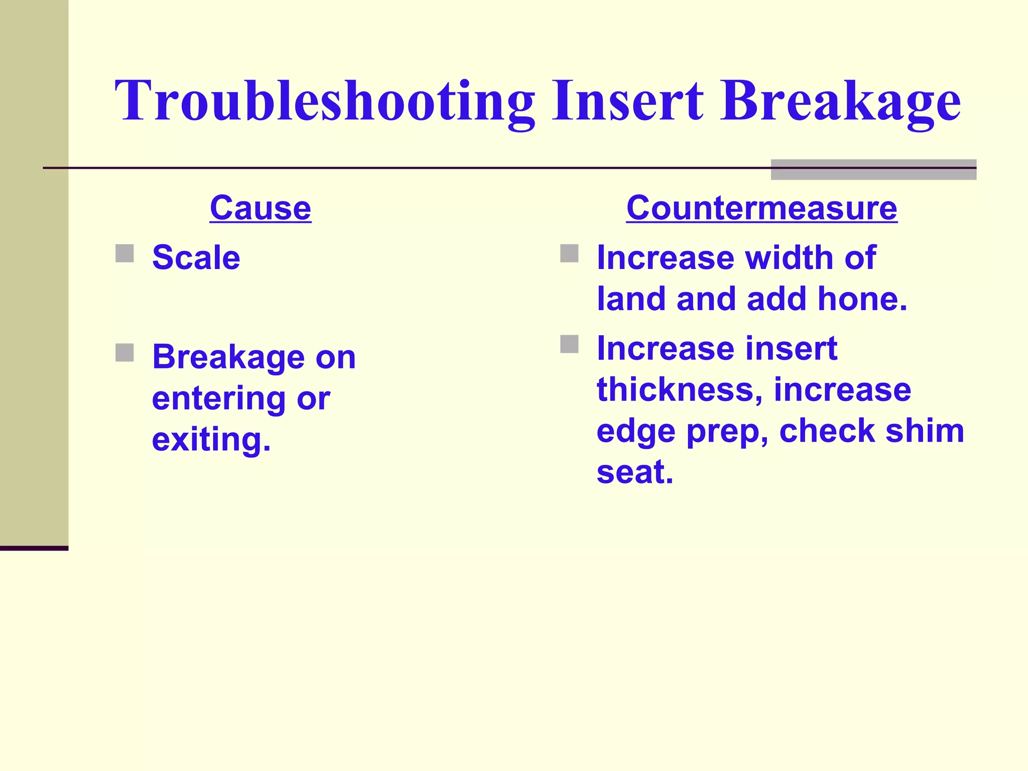
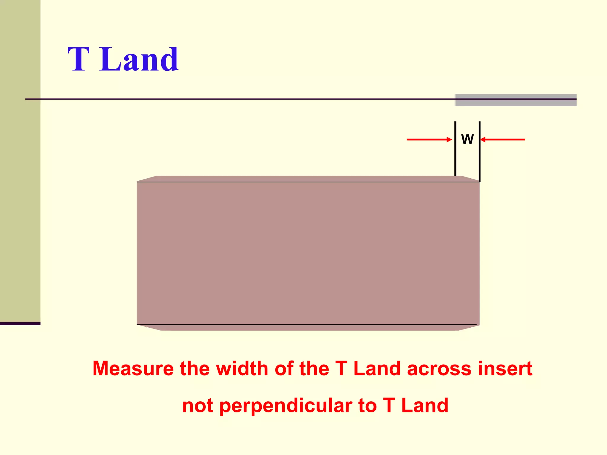
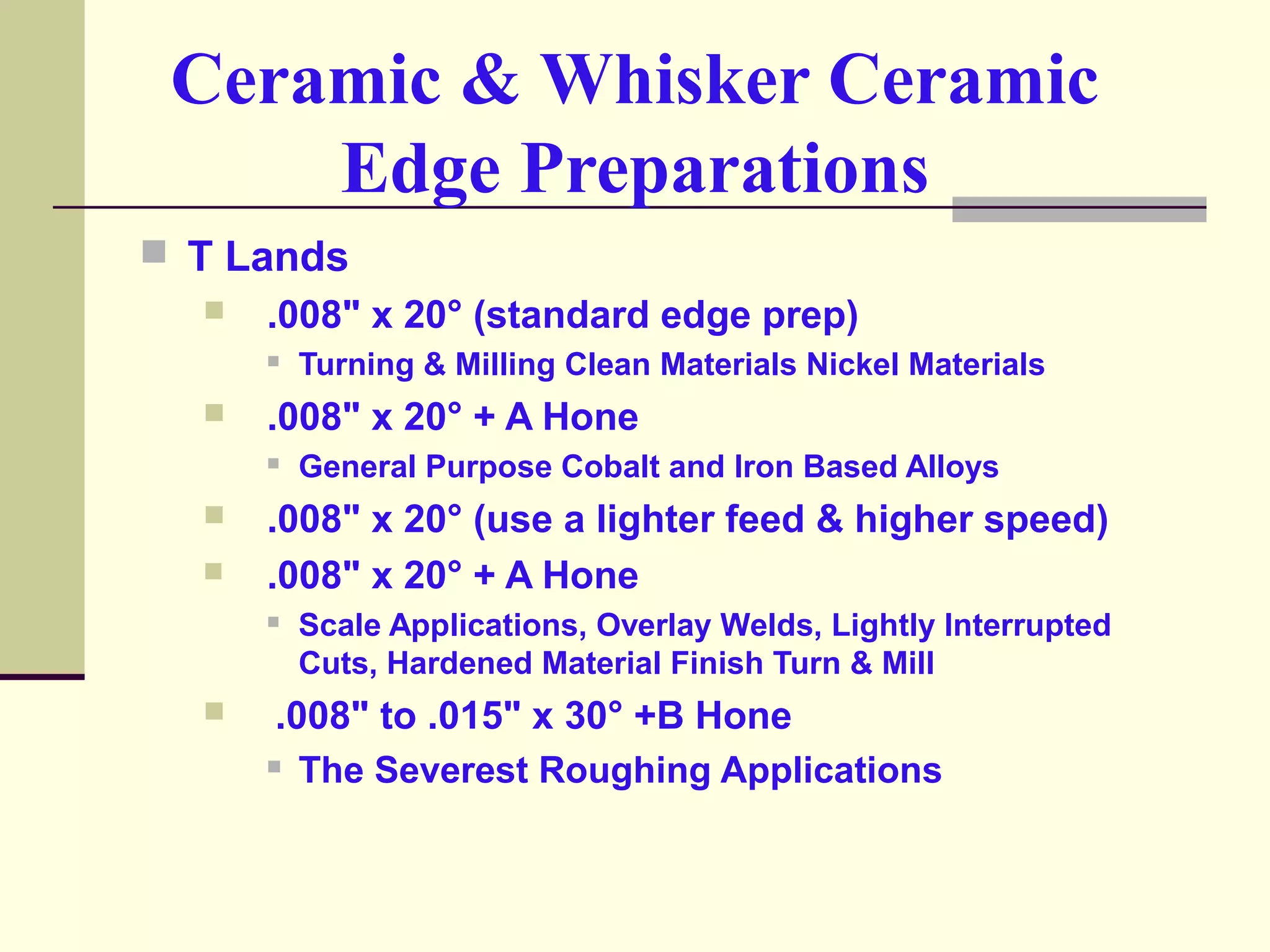
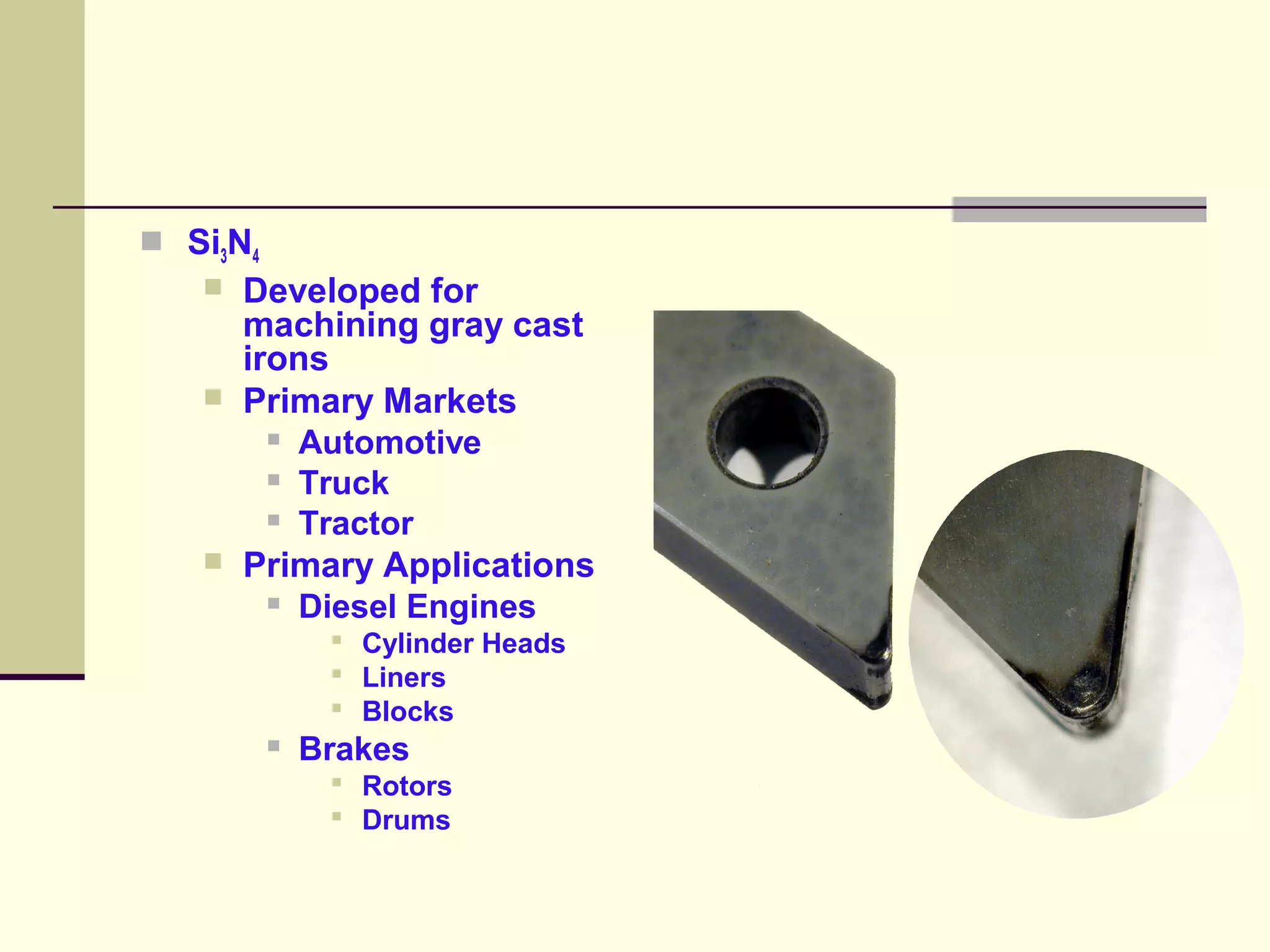
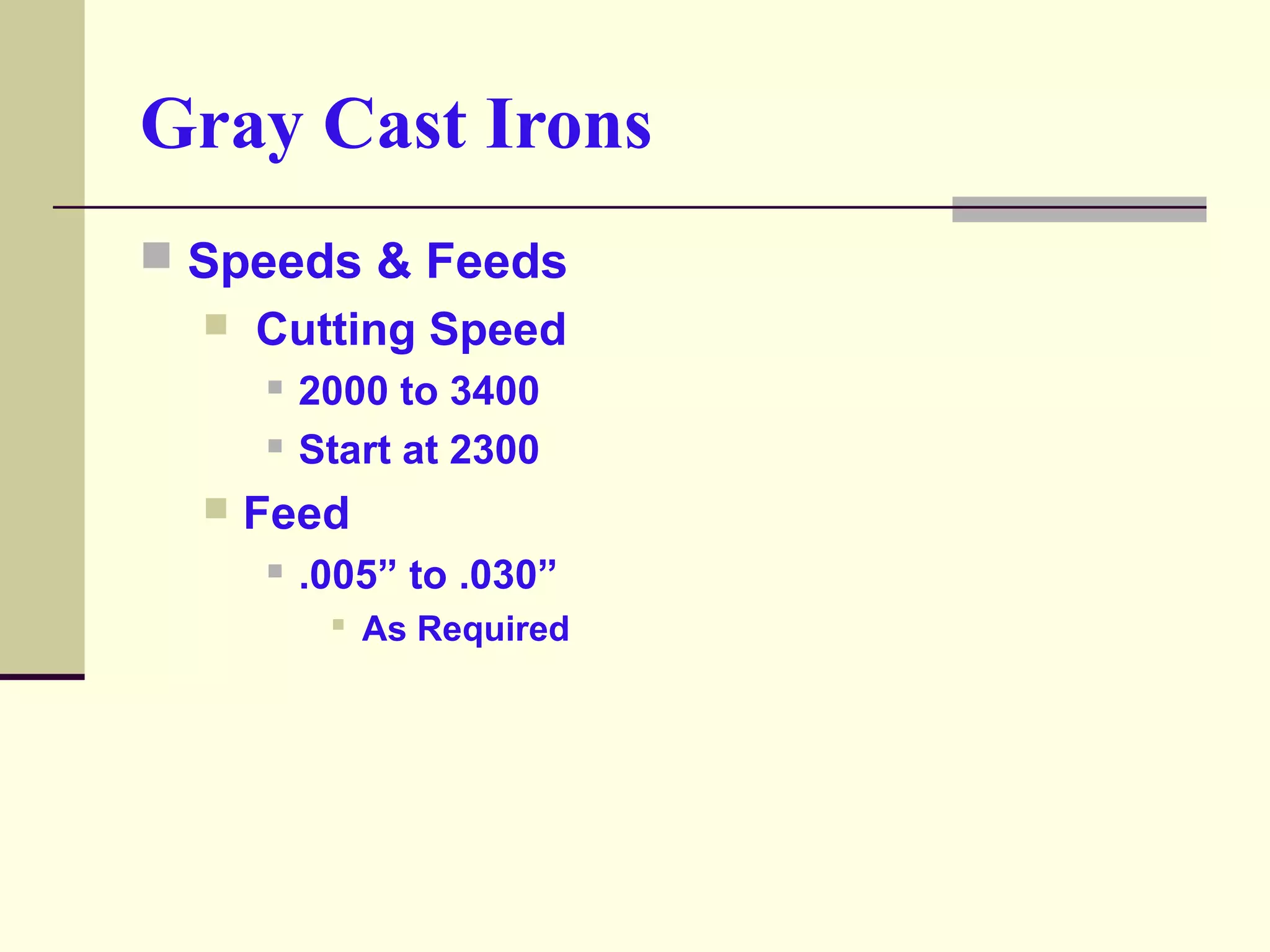
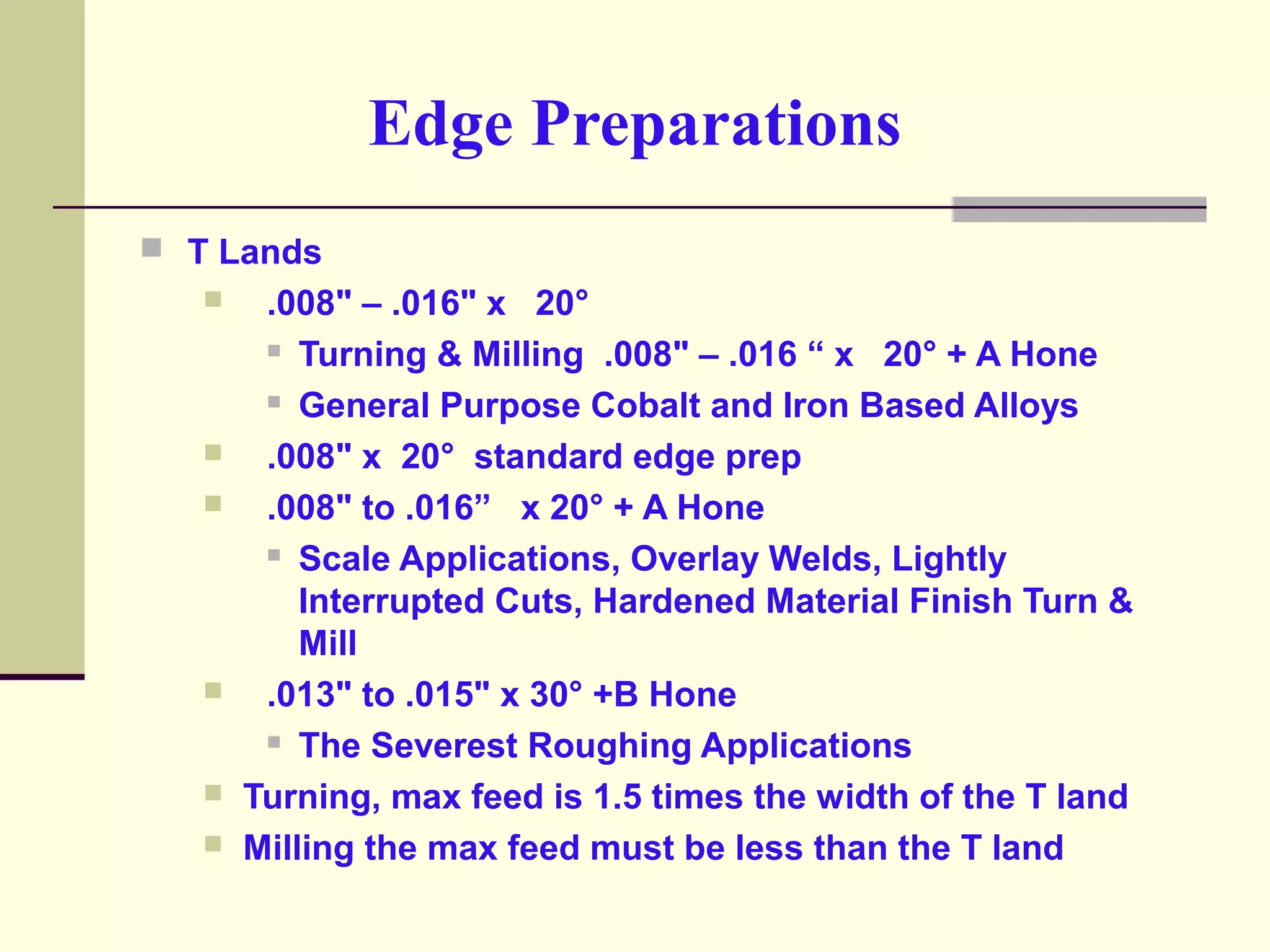

This document provides guidelines for machining various materials with ceramic and whisker ceramic inserts. It addresses machining nickel-based alloys, gray cast iron, and provides information on edge preparations, speeds and feeds, tool geometries, and troubleshooting tool wear and breakage. Guidelines are given for chamfering parts, varying depth of cut, ramping cuts, and other techniques to improve tool life when machining difficult materials like nickel alloys and gray cast iron.


