The document discusses opto-electronic measurement systems produced by Shape Technology Ltd for use in the steel and metal industries. It provides details on several of their key products:
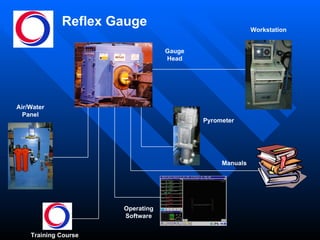
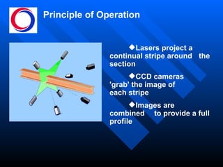
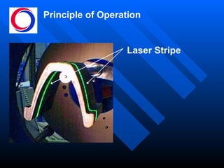
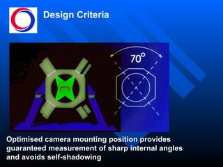
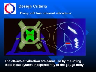
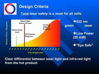
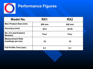
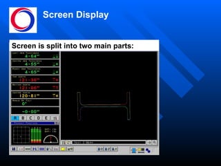
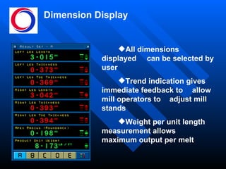
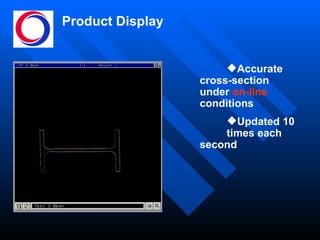
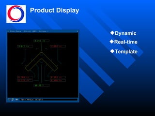
- The Reflex Gauge uses lasers and cameras to take real-time profile measurements of sections on rolling mills. It provides dimensional data to mill operators.
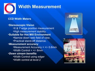
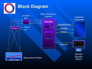
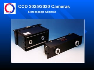
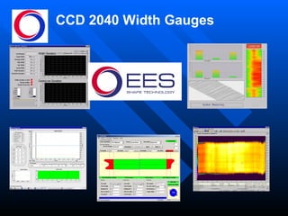
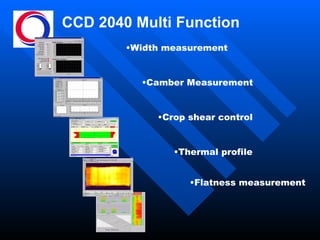
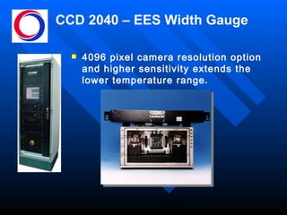
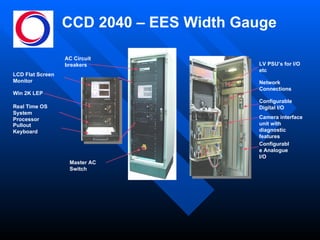
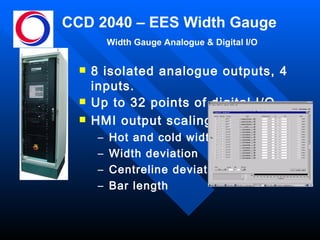
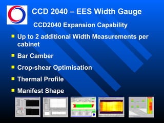
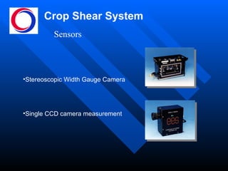
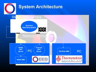
- Width gauges use CCD cameras to measure the width of flat products with high accuracy to help control widths.
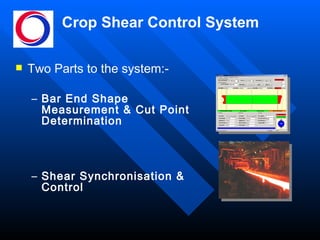
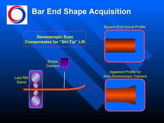
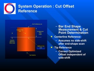
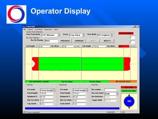
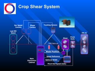
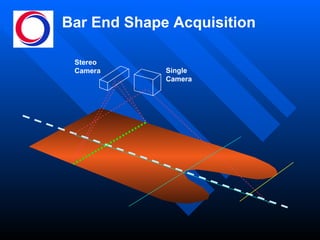
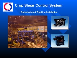
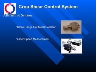
- A crop shear optimization system uses cameras to measure bar end shapes and determine optimal cutting positions for shears to reduce yield losses.
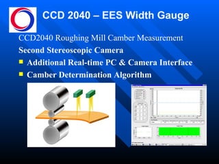
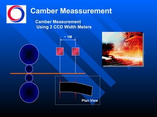
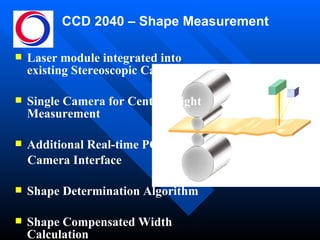
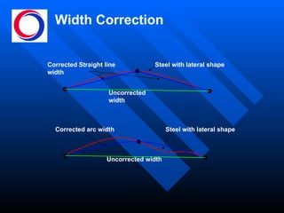
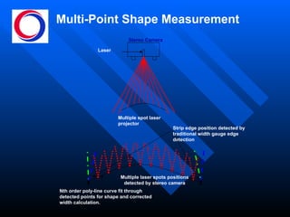
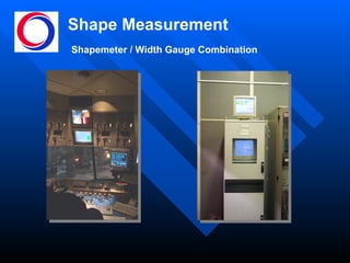
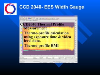
- Additional systems and capabilities are described for camber measurement, shape measurement, thermal profiling and multi-point laser profiling