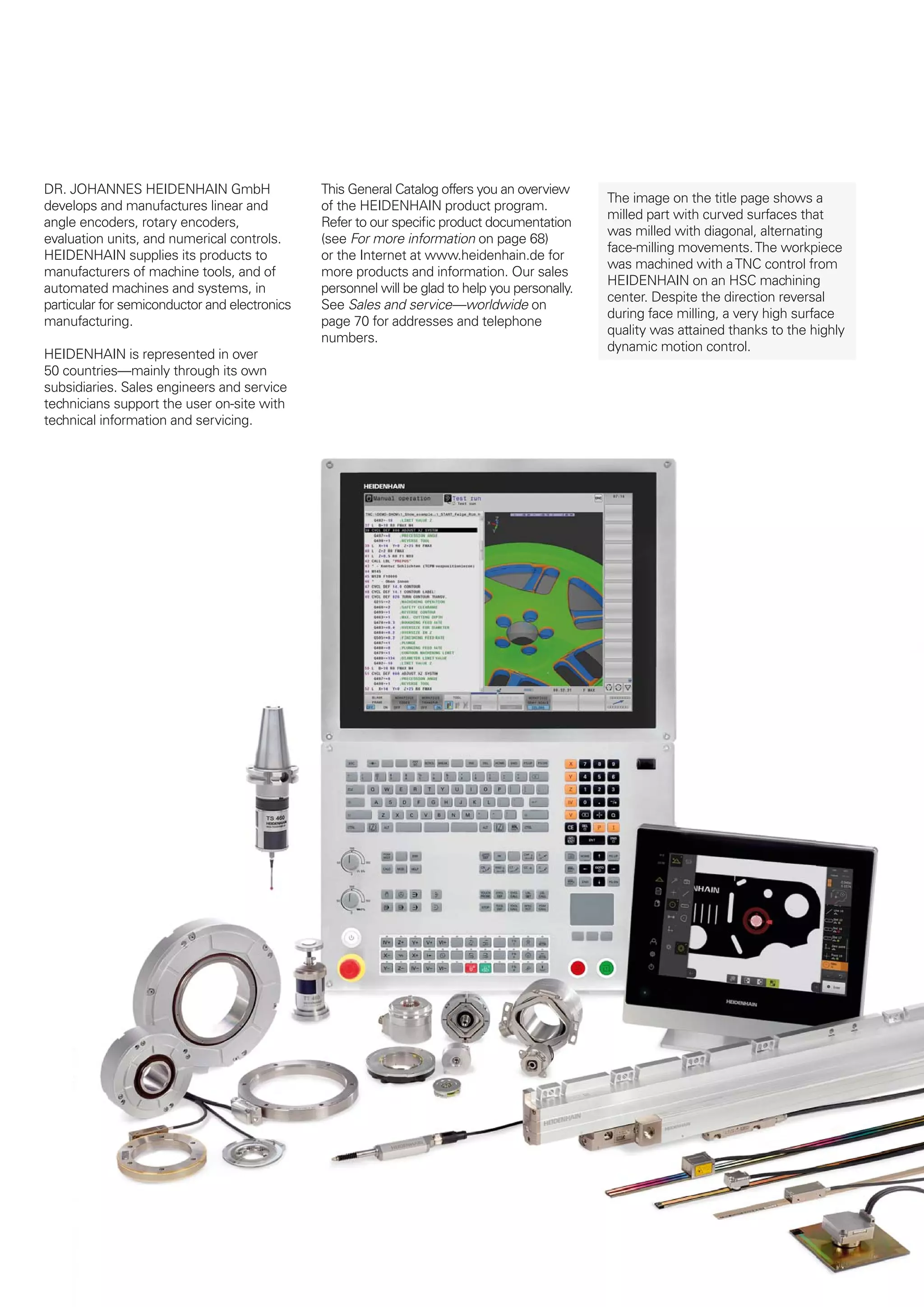
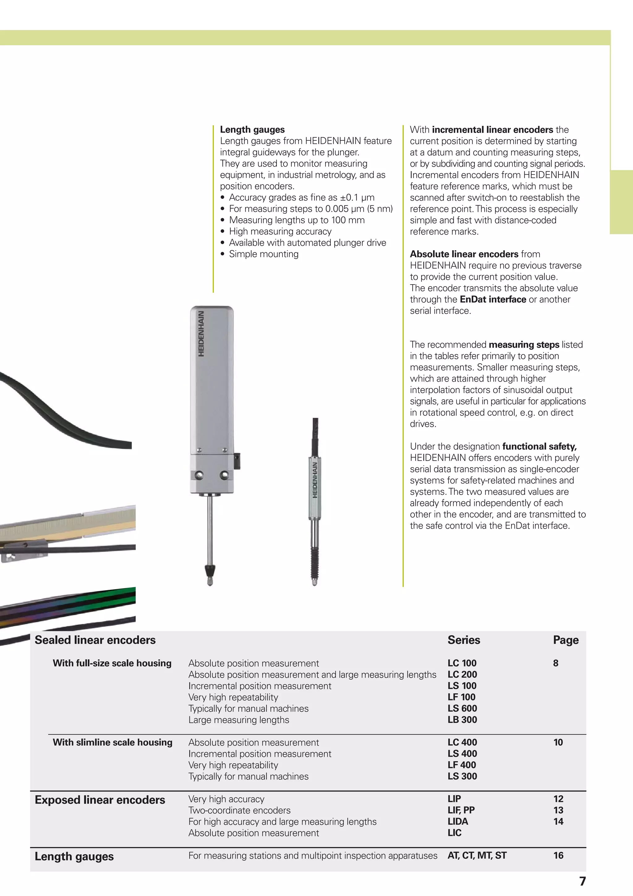
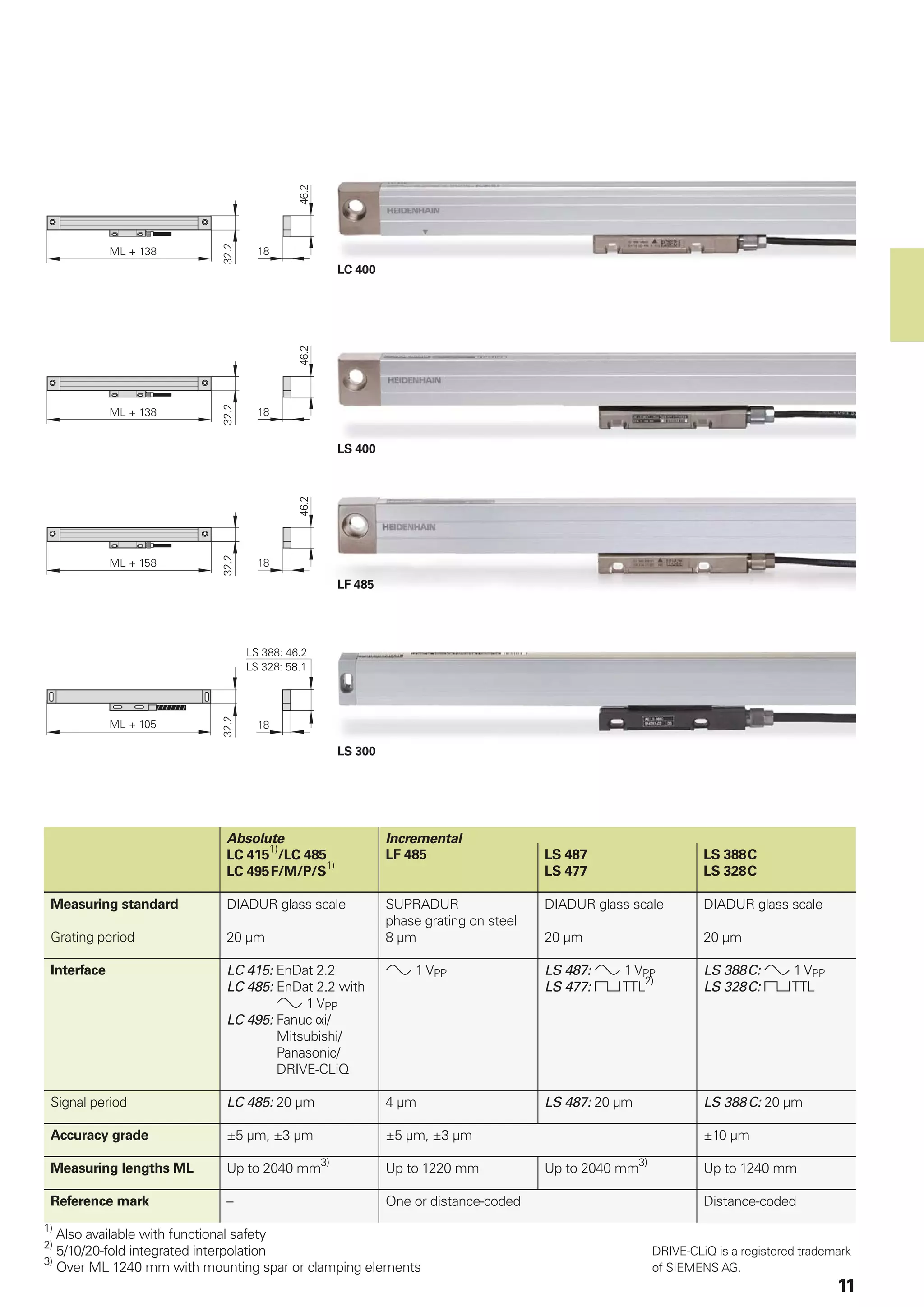
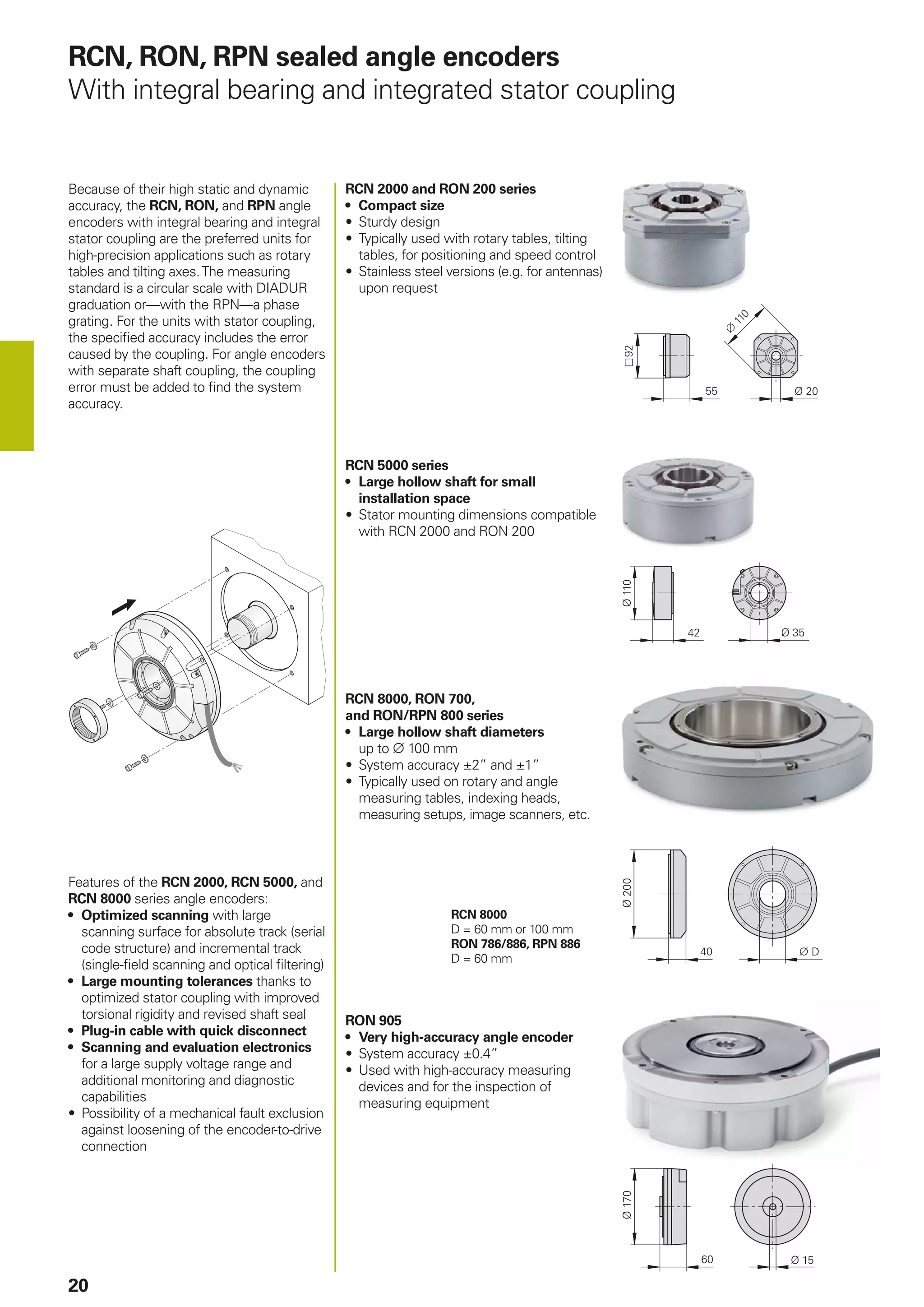
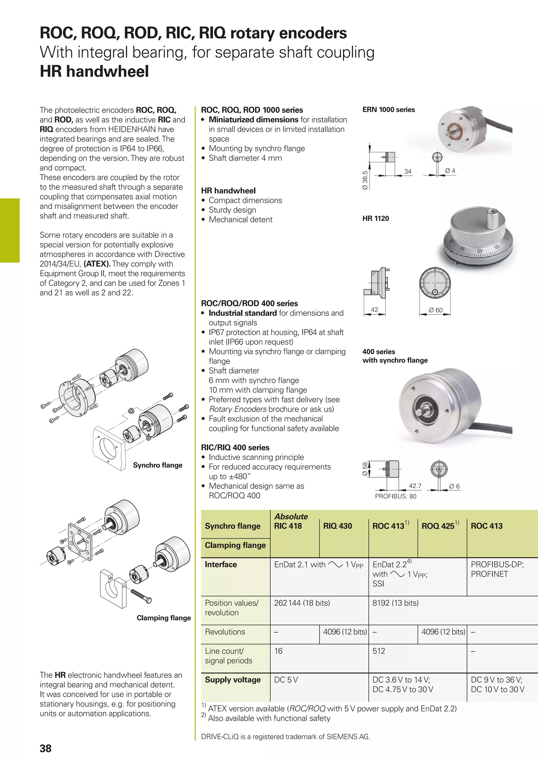
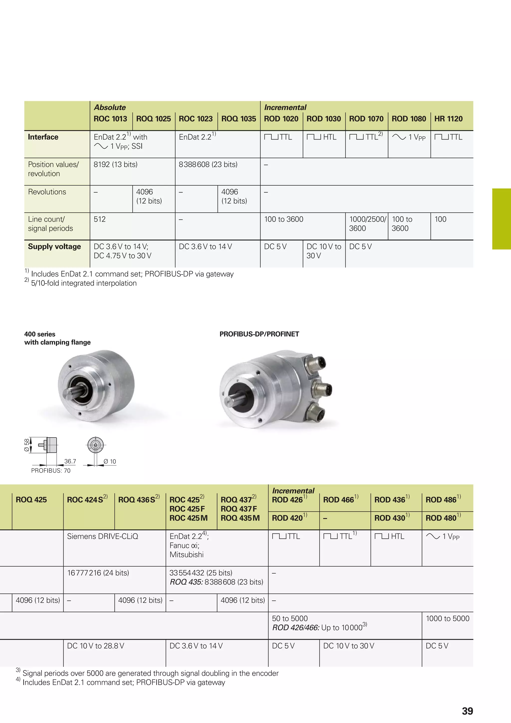
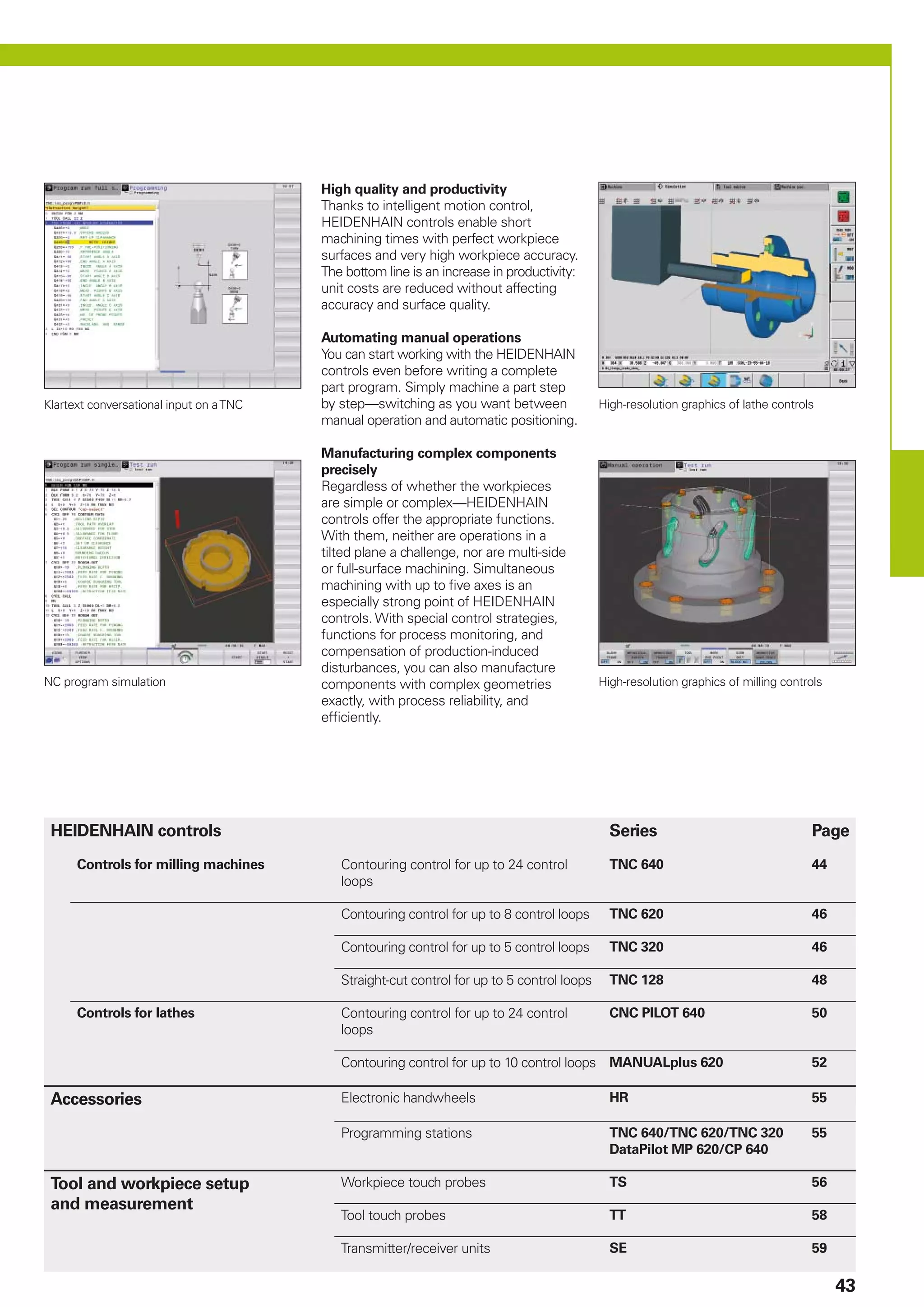
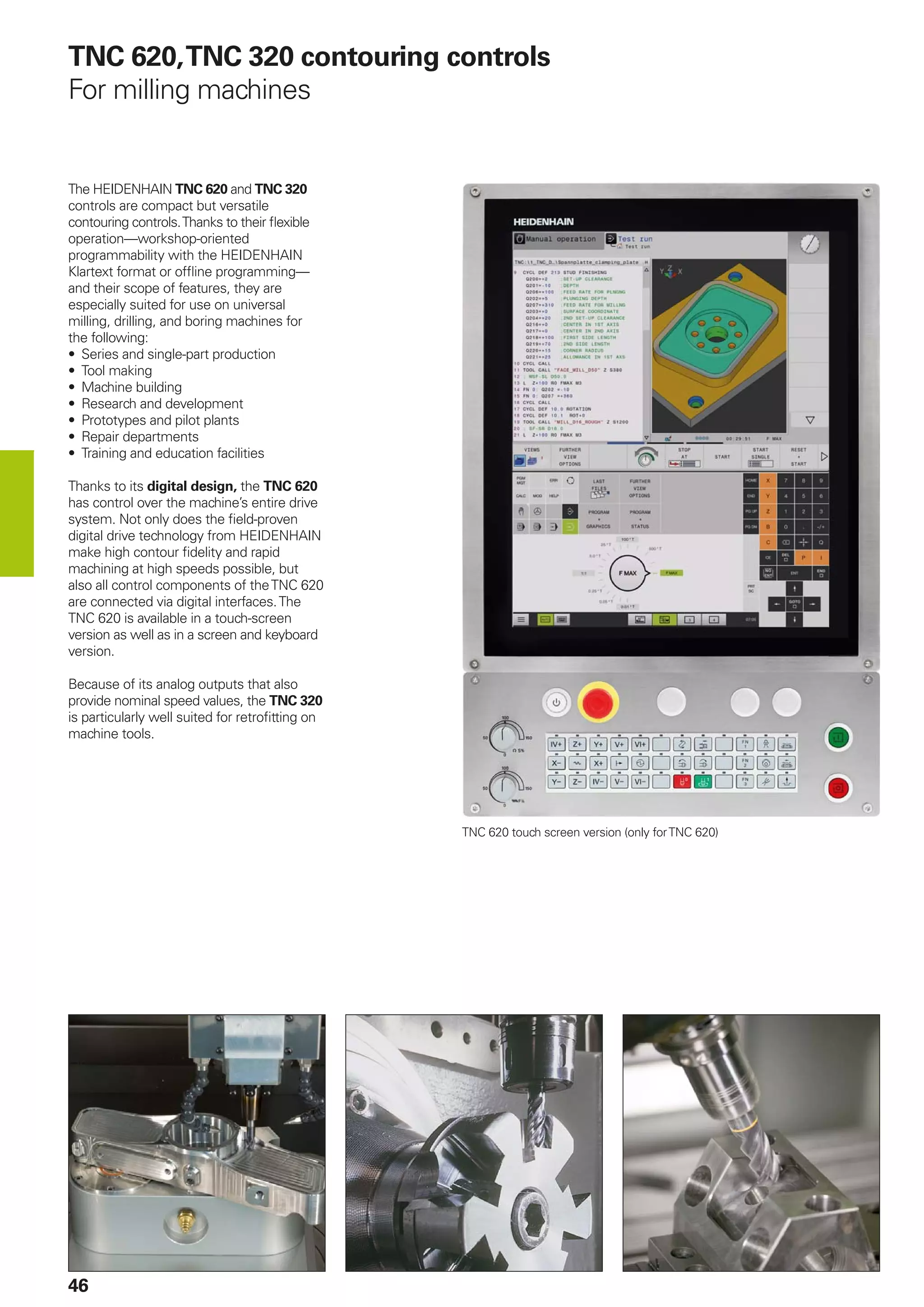
In this PDF there are a number of step-by-step instruction guides that brief about Linear encoders, angle encoders and rotary encoders . These tutorials equip even the most novice user. Contact MDS Laser today for more info. https://mds-laser.com/linear-encoders/
Heidenhain General Catalog Linear Encoderssainothanjames
In this PDF there are a number of step-by-step instruction guides that brief about Optical Linear encoders, angle encoders and rotary encoders . These tutorials equip even the most novice user. Contact MDS Laser today for more info. https://bit.ly/3vtSALF
Introduction to CNC machine and Hardware. aman1312
Complete detailing of cnc machine and its operations with its required hardware necessary for increasing its Automation and increasing its manufacturing capability. Also increase in complex shape manufacturing.
The Pneumatics is study of mechanical motion caused by pressurized gases and how this motion can be used to perform engineering tasks.
Pneumatic systems operate on a supply of compressed air which must be available in sufficient quantity and the air used in pneumatic devices is dried and free from moisture so that it does not create any problem to the internal parts of the system and avoid corrosive actions too.
The compressed air is delivered by the compressor which is a machine that takes in air or gas at a certain pressure and delivered the air at a high pressure.
This machine is pneumatic powered machine and electrical energy is used to operate which has low co-efficient of friction and air.
This machine is designed in solid-works software (module 2017).
A numerical control system in which the data handling, control sequences, and response to input is determined by an on-board computer system at the machine tool.
This describes the mechanism of Computer Numerical Control along with its types, control system, motion system, Programming of CNC, G codes, Part programming, adaptive control machining etc.
Centre lathe, constructional features, specification, operations – taper turning methods, thread cutting methods, special attachments, machining time and power estimation. Capstan and turret lathes- tool layout – automatic lathes: semi automatic – single spindle : Swiss type, automatic screw type – multi spindle:
One of the welding processes that used in Engineering field is the resistance welding. There are several types of welding processes similar to this, but resistance welding has its unique features.
Thanks for the colleagues who give this slides to publish.
The fluid discharged by the pump is directed to the ‘hydraulic actuator’.Theactuatorconvertthepressureenergyofthefluid into mechanical energy. There are 3 basic type of hydraulic actuator.
• Theactuatorsconvertthefluidpressuretoasuitablelinearor rotary motion.
• Linearmotion–Hydrauliccylinder
• Rotary motion – Hydro motor
• Rotarymotion–Semi-rotaryactuator
MACHINING OPERATIONS AND MACHINE TOOLS
Methods of Holding the Work in a Lathe (Chuck,Collet,face Plate,Holding the Work Between Centers)
Work Holding for Drill Presses
Boring Drilling, Reaming, Tapping Milling
Peripheral Milling vs. Face Milling
Shaper and Planer
Broaching
Medición de diámetros interiores al momento de rectificado o mecanizado de piezas tipo flecha.
Preciso y automático, retroalimenta a la maquina CNC para ajustar el mecanizado.
Solo por Jenoptik.
The company is engaged in designing and manufacturing encoders for precise position and motion control. What started four decades ago as an offshoot of Machine Tool Manufacturing , is now a world class company offering solutions globally in precision measurement. Having Customer focus and team work as core values, EMS has innovated and continually improved their products to offer an optimal solutions to changing markets.
Today, we are an ISO 9001:2015 company with state of the art factory having integral facilities for everything from design to delivery under one roof.
Medición en linea de producción a varios niveles de automatización.
Con aire, con lvdts y óptico, son las soluciones que ofrecemos para el sector automotriz de alta precisión.
Rugosidad y contorno en un mismo equipo.
Equipo automatico para aplicaciones en laboratorio o piso de producción.
Mayor información: carlos.ramirez@hommel-etamic.com
Medicion de contorno y forma de piezas tipo flecha, cigüeñales, arbol de levas, partes de transmicion,etc.
Somos lideres mundiales en este segmento!!!!
Remote sensing and monitoring are changing the mining industry for the better. These are providing innovative solutions to long-standing challenges. Those related to exploration, extraction, and overall environmental management by mining technology companies Odisha. These technologies make use of satellite imaging, aerial photography and sensors to collect data that might be inaccessible or from hazardous locations. With the use of this technology, mining operations are becoming increasingly efficient. Let us gain more insight into the key aspects associated with remote sensing and monitoring when it comes to mining.
RMD24 | Debunking the non-endemic revenue myth Marvin Vacquier Droop | First ...BBPMedia1
Marvin neemt je in deze presentatie mee in de voordelen van non-endemic advertising op retail media netwerken. Hij brengt ook de uitdagingen in beeld die de markt op dit moment heeft op het gebied van retail media voor niet-leveranciers.
Retail media wordt gezien als het nieuwe advertising-medium en ook mediabureaus richten massaal retail media-afdelingen op. Merken die niet in de betreffende winkel liggen staan ook nog niet in de rij om op de retail media netwerken te adverteren. Marvin belicht de uitdagingen die er zijn om echt aansluiting te vinden op die markt van non-endemic advertising.
Premium MEAN Stack Development Solutions for Modern BusinessesSynapseIndia
Stay ahead of the curve with our premium MEAN Stack Development Solutions. Our expert developers utilize MongoDB, Express.js, AngularJS, and Node.js to create modern and responsive web applications. Trust us for cutting-edge solutions that drive your business growth and success.
Know more: https://www.synapseindia.com/technology/mean-stack-development-company.html
Enterprise Excellence is Inclusive Excellence.pdfKaiNexus
Enterprise excellence and inclusive excellence are closely linked, and real-world challenges have shown that both are essential to the success of any organization. To achieve enterprise excellence, organizations must focus on improving their operations and processes while creating an inclusive environment that engages everyone. In this interactive session, the facilitator will highlight commonly established business practices and how they limit our ability to engage everyone every day. More importantly, though, participants will likely gain increased awareness of what we can do differently to maximize enterprise excellence through deliberate inclusion.
What is Enterprise Excellence?
Enterprise Excellence is a holistic approach that's aimed at achieving world-class performance across all aspects of the organization.
What might I learn?
A way to engage all in creating Inclusive Excellence. Lessons from the US military and their parallels to the story of Harry Potter. How belt systems and CI teams can destroy inclusive practices. How leadership language invites people to the party. There are three things leaders can do to engage everyone every day: maximizing psychological safety to create environments where folks learn, contribute, and challenge the status quo.
Who might benefit? Anyone and everyone leading folks from the shop floor to top floor.
Dr. William Harvey is a seasoned Operations Leader with extensive experience in chemical processing, manufacturing, and operations management. At Michelman, he currently oversees multiple sites, leading teams in strategic planning and coaching/practicing continuous improvement. William is set to start his eighth year of teaching at the University of Cincinnati where he teaches marketing, finance, and management. William holds various certifications in change management, quality, leadership, operational excellence, team building, and DiSC, among others.
Accpac to QuickBooks Conversion Navigating the Transition with Online Account...PaulBryant58
This article provides a comprehensive guide on how to
effectively manage the convert Accpac to QuickBooks , with a particular focus on utilizing online accounting services to streamline the process.
Explore our most comprehensive guide on lookback analysis at SafePaaS, covering access governance and how it can transform modern ERP audits. Browse now!
[Note: This is a partial preview. To download this presentation, visit:
https://www.oeconsulting.com.sg/training-presentations]
Sustainability has become an increasingly critical topic as the world recognizes the need to protect our planet and its resources for future generations. Sustainability means meeting our current needs without compromising the ability of future generations to meet theirs. It involves long-term planning and consideration of the consequences of our actions. The goal is to create strategies that ensure the long-term viability of People, Planet, and Profit.
Leading companies such as Nike, Toyota, and Siemens are prioritizing sustainable innovation in their business models, setting an example for others to follow. In this Sustainability training presentation, you will learn key concepts, principles, and practices of sustainability applicable across industries. This training aims to create awareness and educate employees, senior executives, consultants, and other key stakeholders, including investors, policymakers, and supply chain partners, on the importance and implementation of sustainability.
LEARNING OBJECTIVES
1. Develop a comprehensive understanding of the fundamental principles and concepts that form the foundation of sustainability within corporate environments.
2. Explore the sustainability implementation model, focusing on effective measures and reporting strategies to track and communicate sustainability efforts.
3. Identify and define best practices and critical success factors essential for achieving sustainability goals within organizations.
CONTENTS
1. Introduction and Key Concepts of Sustainability
2. Principles and Practices of Sustainability
3. Measures and Reporting in Sustainability
4. Sustainability Implementation & Best Practices
To download the complete presentation, visit: https://www.oeconsulting.com.sg/training-presentations
Falcon stands out as a top-tier P2P Invoice Discounting platform in India, bridging esteemed blue-chip companies and eager investors. Our goal is to transform the investment landscape in India by establishing a comprehensive destination for borrowers and investors with diverse profiles and needs, all while minimizing risk. What sets Falcon apart is the elimination of intermediaries such as commercial banks and depository institutions, allowing investors to enjoy higher yields.
RMD24 | Retail media: hoe zet je dit in als je geen AH of Unilever bent? Heid...BBPMedia1
Grote partijen zijn al een tijdje onderweg met retail media. Ondertussen worden in dit domein ook de kansen zichtbaar voor andere spelers in de markt. Maar met die kansen ontstaan ook vragen: Zelf retail media worden of erop adverteren? In welke fase van de funnel past het en hoe integreer je het in een mediaplan? Wat is nu precies het verschil met marketplaces en Programmatic ads? In dit half uur beslechten we de dilemma's en krijg je antwoorden op wanneer het voor jou tijd is om de volgende stap te zetten.
RMD24 | Retail media: hoe zet je dit in als je geen AH of Unilever bent? Heid...
Heidenhain general catalog-linear encoders
1. General Catalog
Linear Encoders
Length Gauges
Angle Encoders
Rotary Encoders
Contouring Controls
Touch Probes
Evaluation Electronics
Digital Readouts
09/2018
2. DR. JOHANNES HEIDENHAIN GmbH
develops and manufactures linear and
angle encoders, rotary encoders,
evaluation units, and numerical controls.
HEIDENHAIN supplies its products to
manufacturers of machine tools, and of
automated machines and systems, in
particular for semiconductor and electronics
manufacturing.
HEIDENHAIN is represented in over
50 countries—mainly through its own
subsidiaries. Sales engineers and service
technicians support the user on-site with
technical information and servicing.
This General Catalog offers you an overview
of the HEIDENHAIN product program.
Refer to our specific product documentation
(see For more information on page 68)
or the Internet at www.heidenhain.de for
more products and information. Our sales
personnel will be glad to help you personally.
See Sales and service—worldwide on
page 70 for addresses and telephone
numbers.
The image on the title page shows a
milled part with curved surfaces that
was milled with diagonal, alternating
face-milling movements.The workpiece
was machined with aTNC control from
HEIDENHAIN on an HSC machining
center. Despite the direction reversal
during face milling, a very high surface
quality was attained thanks to the highly
dynamic motion control.
3. Contents
Fundamentals and processes 4
Precision graduations—the foundation for high accuracy 5
Length measurement 6
Sealed linear encoders
Exposed linear encoders
Length gauges
Angle measurement 18
Sealed angle encoders
Angle encoder modules
Modular angle encoders
Rotary encoders
Machine tool control 42
Straight-cut control for milling machines
Contouring controls for milling machines and machining centers
Contouring controls for milling-turning machines and machining centers
Contouring controls for lathes
Programming stations
Tool and workpiece setup and measurement 56
Workpiece touch probes
Tool touch probes
Measured value acquisition and display 60
Evaluation electronics for metrology applications
Digital readouts for manually operated machine tools
Interface electronics
For more information 68
Sales and service 70
4. 4
Fundamentals and processes
The high quality of HEIDENHAIN products
depends on special production facilities
and measuring equipment. Masters and
submasters for scale manufacturing are
produced in a clean room with special
measures for temperature stabilization and
vibration insulation.The copying machines
and the machines required for the
manufacture and measurement of linear
and circular graduations are largely
developed and built by HEIDENHAIN.
Competence in the area of linear and
angular metrology is reflected by a large
number of customized solutions for users.
Among other implementations, they
include the measuring and test equipment
developed and built for standard laboratories
and the angle encoders for telescopes and
satellite receiving antennas.The products
in the standard HEIDENHAIN product
program naturally profit from the knowledge
gained.
30 m long measuring machine for scale tapes Vacuum machine for application of chromium layers
Angle comparator, measuring step approx. 0.001” ALMA radio telescope in Chajnantor, Chile (photo courtesy of ESO)
5. 5
Precision graduations—the foundation for high accuracy
The heart of a HEIDENHAIN encoder is its
measuring standard, usually in the form of
a grating with typical line widths of 0.25 µm
to 10 µm.These precision graduations are
manufactured in a process invented by
HEIDENHAIN (e.g. DIADUR or METALLUR)
and are a decisive factor in the function
and accuracy of encoders.The graduations
consist of lines and gaps at defined intervals
with very little deviation, forming structures
with very high edge definition.These
graduations are resistant to mechanical and
chemical influences and can tolerate vibration
and shock. All measuring standards have
a defined thermal behavior.
Phase grating with approx. 0.25 µm grating height
DIADUR
DIADUR precision graduations are
composed of an extremely thin layer of
chromium on a substrate—usually of glass
or glass ceramic.The accuracy of the
graduation structure lies within the micron
and submicron range.
AURODUR
AURODUR graduations consist of highly
reflective gold lines and matte etched gaps.
AURODUR graduations are usually on steel
carriers.
METALLUR
With its special optical composition of
reflective gold layers, METALLUR
graduations show a virtually planar
structure.They are therefore particularly
tolerant to contamination.
Phase gratings
Special manufacturing processes make it
possible to produce three-dimensional
graduation structures, possessing certain
optical characteristics.The structure widths
are in the range of a few micrometers
down to quarters of a micrometer.
SUPRADUR
Graduations manufactured with the
SUPRADUR process function optically like
three-dimensional phase gratings, but they
have a planar structure and are therefore
particularly insensitive to contamination.
OPTODUR
The OPTODUR process produces
graduation structures with particularly high
reflectance. Its composition as an optically
three dimensional, planar structure is
similar to the SUPRADUR graduation.
MAGNODUR
Thin magnetically active layers in the
micron range are structured for very fine,
magnetized graduations.
DIADUR and METALLUR graduations on various carrier materials
6. 6
Length measurement
Sealed linear encoders are available with
• Full-size scale housing
– For high vibration loading
– Up to 30 m measuring length
(72 m upon request)
• Slimline scale housing
– For limited installation space
– Measuring length up to 2040 mm
(for measuring lengths starting from
1240 mm, mounting via mounting spar
or tensioning elements)
The aluminum housing of a HEIDENHAIN
sealed linear encoder protects the scale,
scanning carriage, and its guideway from
chips, dust, and fluids. Downward-oriented
elastic lips seal the housing.
The scanning carriage travels along the
scale on a low-friction guide. It is connected
to the external mounting block by a coupling
that compensates unavoidable misalignment
between the scale and the machine
guideways.
Scanning carriage
DIADUR
linear scale
Light source
Sealing lips Mounting block
Electronic
scanning
Exposed linear encoders
Exposed linear encoders from HEIDENHAIN
operate with no mechanical contact
between the scanning head and the scale
or scale tape.Typical areas of application
for these encoders include measuring
machines, comparators, and other
precision devices, as well as production
and measuring equipment, for example
in the semiconductor industry.
• Accuracy grades of ±0.5 µm and better
• For measuring steps to 0.001 µm (1 nm)
• Measuring lengths up to 30 m
• No friction between scanning head and
scale
• Small dimensions and low mass
• High traversing speeds
Sealed linear encoders
Sealed linear encoders from HEIDENHAIN
are protected from dust, chips, and splash
fluids, and are ideal for operation on
machine tools.
• Accuracy grades as fine as ±2 µm
• Measuring steps to 0.001 µm
• Measuring lengths up to 30 m
(72 m upon request)
• Fast and simple installation
• Large mounting tolerances
• High acceleration loading
• Protection against contamination
7. 7
Length gauges
Length gauges from HEIDENHAIN feature
integral guideways for the plunger.
They are used to monitor measuring
equipment, in industrial metrology, and as
position encoders.
• Accuracy grades as fine as ±0.1 µm
• For measuring steps to 0.005 µm (5 nm)
• Measuring lengths up to 100 mm
• High measuring accuracy
• Available with automated plunger drive
• Simple mounting
With incremental linear encoders the
current position is determined by starting
at a datum and counting measuring steps,
or by subdividing and counting signal periods.
Incremental encoders from HEIDENHAIN
feature reference marks, which must be
scanned after switch-on to reestablish the
reference point.This process is especially
simple and fast with distance-coded
reference marks.
Absolute linear encoders from
HEIDENHAIN require no previous traverse
to provide the current position value.
The encoder transmits the absolute value
through the EnDat interface or another
serial interface.
The recommended measuring steps listed
in the tables refer primarily to position
measurements. Smaller measuring steps,
which are attained through higher
interpolation factors of sinusoidal output
signals, are useful in particular for applications
in rotational speed control, e.g. on direct
drives.
Under the designation functional safety,
HEIDENHAIN offers encoders with purely
serial data transmission as single-encoder
systems for safety-related machines and
systems.The two measured values are
already formed independently of each
other in the encoder, and are transmitted to
the safe control via the EnDat interface.
Sealed linear encoders Series Page
With full-size scale housing Absolute position measurement
Absolute position measurement and large measuring lengths
Incremental position measurement
Very high repeatability
Typically for manual machines
Large measuring lengths
LC 100
LC 200
LS 100
LF 100
LS 600
LB 300
8
With slimline scale housing Absolute position measurement
Incremental position measurement
Very high repeatability
Typically for manual machines
LC 400
LS 400
LF 400
LS 300
10
Exposed linear encoders Very high accuracy
Two-coordinate encoders
For high accuracy and large measuring lengths
Absolute position measurement
LIP
LIF, PP
LIDA
LIC
12
13
14
Length gauges For measuring stations and multipoint inspection apparatuses AT, CT, MT, ST 16
8. 8
LC, LF, LS, LB sealed linear encoders
With full-size scale housing
Linear encoders with full-size scale
housing are characterized particularly by
their high tolerance to vibration.
Absolute linear encoders of the LC 100
and LC 200 series provide the absolute
position value without requiring any
previous traverse. Depending on the
version, incremental signals can be output
additionally.The LC 100 can be mounted
to the same mating dimensions as the
incremental linear encoders of the LS 100
series, and feature the same mechanical
design. Because of their high accuracy and
defined thermal behavior, LC 100 and
LS 100 series linear encoders are especially
well suited for use on numerically
controlled machine tools.
The incremental encoders of the LF type
feature measuring standards with relatively
fine grating periods.This makes them
particularly attractive for applications requiring
very high repeatability.
The LS 600 series incremental linear
encoders are used for simple positioning
tasks, for example on manual machine
tools.
The LC 200 (absolute) and LB (incremental)
linear encoders were conceived for very
long measuring lengths.Their measuring
standard—a steel tape with METALLUR or
AURODUR graduation—is delivered as a
single piece, and after the housing sections
have been mounted, is pulled into the
housing, drawn to a defined tension and
fixed at both ends to the machine casting.
LF 185
• Very high repeatability
• Thermal behavior similar to steel or
cast iron
• High vibration rating
• Two mounting attitudes
• Single-field scanning
LC 100 series
• Absolute position measurement
• Defined thermal behavior
• High vibration rating
• Two mounting attitudes
• Single-field scanning
LS 100 series
• Incremental position measurement
• Defined thermal behavior
• High vibration rating
• Two mounting attitudes
• Single-field scanning
LS 600 series
• Typically for manual machines
• Simple installation
LB 382
• For large measuring lengths
up to 30 m4)
• Defined thermal behavior
• High vibration rating
• Two mounting attitudes
• Single-field scanning
Absolute
LC 115
1)
/LC 185
LC 195F/M/P/S1)
LC 211/LC 281
LC 291F/M
Measuring standard
Grating period
DIADUR glass scale
20 µm
METALLUR steel scale tape
40 µm
Interface LC 115: EnDat 2.2
LC 185: EnDat 2.2 with
1 VPP
LC 195: Fanuc i/Mitsubishi/
Panasonic/DRIVE-CLiQ
LC 211: EnDat 2.2
LC 281: EnDat 2.2 with
1 VPP
LC 291: Fanuc i/Mitsubishi
Signal period LC 185: 20 µm LC 281: 40 µm
Accuracy grade ±5 µm, ±3 µm
3)
±5 µm
Measuring lengths ML Up to 4240 mm Up to 28 040 mm
5)
Reference mark –
1)
Also available with functional safety
2)
5/10/20-fold integrated interpolation
LC 200 series
• Absolute position measurement for
large measuring lengths up to 28 m
• Defined thermal behavior
• High vibration rating
• Two mounting attitudes
• Single-field scanning
9. LC 100
LF 185
LC 200
LS 600
9
Incremental
LF 185 LS 187
LS 177
LS 688C
LS 628C
LB 382
SUPRADUR phase grating
on steel
8 µm
DIADUR glass scale
20 µm
DIADUR glass scale
20 µm
AURODUR steel scale tape
40 µm
1 VPP LS 187: 1 VPP
LS 177: TTL
2)
LS 688C: 1 VPP
LS 628C: TTL
1 VPP
4 µm LS 187: 20 µm LS 688C: 20 µm 40 µm
±3 µm, ±2 µm ±5 µm, ±3 µm ±10 µm ±5 µm
Up to 3040 mm Up to 3040 mm Up to 30 040 mm4)
One or distance-coded; LS 6xxC: distance-coded
3)
Up to ML 3040 mm
5)
Larger measuring lengths withTNC 640 upon request
4)
Up to ML 72040 mm upon request DRIVE-CLiQ is a registered trademark
of SIEMENS AG.
10. 10
LC, LF, LS sealed linear encoders
With slimline scale housing
Sealed linear encoders with slimline
scale housing are primarily used where
installation space is limited.
Absolute linear encoders of the LC 400
series provide the absolute position value
without requiring any previous traverse.
Like the LS 400 series incremental linear
encoders, their high accuracy and defined
thermal behavior make them especially well
suited for use on numerically controlled
machine tools.
The incremental encoders of the LF type
feature measuring standards with relatively
fine grating periods.This makes them
particularly attractive for applications requiring
very high repeatability.
The LS 300 series incremental linear
encoders are used for simple positioning
tasks, for example on manual machine
tools.
Simple installation with mounting spar
The use of a mounting spar is of great
benefit when mounting slimline linear
encoders. It can be fastened as part of the
machine assembly process.The encoder
is then simply clamped on during final
mounting. Easy exchange also facilitates
servicing.
Moreover, installation with a mounting
spar significantly improves the encoder’s
acceleration behavior.
LF 485
• Very high repeatability
• Thermal behavior similar to steel or
cast iron
• Single-field scanning
LC 400 series
• Absolute position measurement
• Defined thermal behavior
• Single-field scanning
LS 400 series
• Incremental position measurement
• Defined thermal behavior
• Single-field scanning
LS 300 series
• Typically for manual machines
Clamping spring
Scale housing
Mounting block
Mounting spar
Fixed stop
11. LC 400
LS 400
LF 485
LS 300
11
Absolute Incremental
LC 415
1)
/LC 485
LC 495F/M/P/S1)
LF 485 LS 487
LS 477
LS 388C
LS 328C
Measuring standard
Grating period
DIADUR glass scale
20 µm
SUPRADUR
phase grating on steel
8 µm
DIADUR glass scale
20 µm
DIADUR glass scale
20 µm
Interface LC 415: EnDat 2.2
LC 485: EnDat 2.2 with
1 VPP
LC 495: Fanuc i/
Mitsubishi/
Panasonic/
DRIVE-CLiQ
1 VPP LS 487: 1 VPP
LS 477: TTL
2)
LS 388C: 1 VPP
LS 328C: TTL
Signal period LC 485: 20 µm 4 µm LS 487: 20 µm LS 388C: 20 µm
Accuracy grade ±5 µm, ±3 µm ±5 µm, ±3 µm ±10 µm
Measuring lengths ML Up to 2040 mm
3)
Up to 1220 mm Up to 2040 mm
3)
Up to 1240 mm
Reference mark – One or distance-coded Distance-coded
1)
Also available with functional safety
2)
5/10/20-fold integrated interpolation
3)
Over ML 1240 mm with mounting spar or clamping elements
DRIVE-CLiQ is a registered trademark
of SIEMENS AG.
12. 12
LIP
, LIF exposed linear encoders
For very high accuracy
The exposed linear encoders of the LIP
and LIF design are characterized by
small measuring steps together with high
accuracy.The measuring standard is a
phase grating applied to a substrate of
glass or glass ceramic.
LIP and LIF encoders are typically used for:
• Measuring machines and comparators
• Measuring microscopes
• Ultra-precision machines such as diamond
lathes for optical components, facing
lathes for magnetic storage disks, and
grinding machines for ferrite components
• Measuring and production equipment in
the semiconductor industry
• Measuring and production equipment in
the electronics industry
Special vacuum applications in high
vacuum are served by LIF 481V and
LIP 481V (for high vacuum, down to 10–7
bar)
and LIP 481U (for ultrahigh vacuum, down
to 10–11
bar).
LIP 300 series
• Very high resolution with measuring
steps to 1 nm
• Very high repeatability through an
extremely fine signal period
• Defined thermal behavior thanks to a
measuring standard on Zerodur glass
ceramic
LIP 6000 series
• For highly dynamic applications
• For limited installation space
• Measuring step down to 2 nm
• Position detection through limit switches
and homing track
LIP 200 series
• Very high repeatability with compact
dimensions
• Measuring lengths up to 3040 mm
• Measuring step down to 1 nm
• Defined thermal behavior thanks to a
measuring standard on Zerodur glass
ceramic
ML = 70 mm
Incremental
LIP 382 LIP 281
LIP 211
LIP 6081
LIP 6071
Measuring standard
Grating period
DIADUR phase grating
on Zerodur glass ceramic
0.512 µm
OPTODUR phase grating
on Zerodur glass ceramic
2.048 µm
DIADUR phase grating on glass
or Zerodur glass ceramic
4 µm
Interface 1 VPP LIP 281: 1 VPP
LIP 211: EnDat 2.2
1)
LIP 6081: 1 VPP
LIP 6071: TTL
Signal period 0.128 µm LIP 281: 0.512 µm LIP 6081: 4 µm
Accuracy grade ±0.5 µm ±1 µm ±3 µm ±1 µm ±3 µm
Baseline error ±0.075 µm/5 mm ±0.125 µm/5 mm ±0.175 µm/5 mm
Interpolation error
2)
±0.01 nm ±0.4 nm ±4 nm
Measuring lengths ML 70 mm to 270 mm 20 mm to
1020 mm
370 mm to
3040 mm
20 mm to
1020 mm
20 mm to
3040 mm
Reference mark None One One
1)
Absolute position value after scanning the reference mark
2)
Only with encoders with 1 VPP or EnDat 2.2 interface
LIF 400 series
• Fast, simple scale fastening with
PRECIMET adhesive film
• Insensitive to contamination thanks to
SUPRADUR graduation
• Position detection through limit switches
and homing track
13. 13
LIF 481
LIF 471
SUPRADUR phase grating on glass
or Zerodur glass ceramic
8 µm
LIF 481: 1 VPP
LIF 471: TTL
LIF 481: 4 µm
±1 µm (only Zerodur) ± 3 µm
±0.225 µm/5 mm
±12 nm
70 mm to 1020 mm 70 mm to 1640 mm
One
ML = 120 mm
PP exposed linear encoders
Two-coordinate encoders
The PP two-coordinate encoders feature as
measuring standard a planar phase-grating
structure on a glass substrate.This makes
it possible to measure positions in a plane.
Applications include:
• Measuring and production equipment in
the semiconductor industry
• Measuring and production equipment in
the electronics industry
• Extremely fast X-Y tables
• Measuring machines and comparators
• Measuring microscopes
Incremental
PP 281
Measuring standard
Grating period
DIADUR phase grating on glass
8 µm
Interface 1 VPP
Signal period 4 µm
Accuracy grade ±2 µm
Interpolation error ±12 nm
Measuring range 68 mm x 68 mm,
other measuring ranges upon request
Reference mark One per coordinate
14. 14
LIC, LIDA exposed linear encoders
For high accuracy and large measuring lengths
The LIC and LIDA exposed linear encoders
are designed for high traversing speeds
up to 10 m/s and large measuring lengths
of up to 30 m.
LIC encoders make absolute position
measurement possible over measuring
lengths up to 28 m. In their dimensions
they correspond to LIDA 400 and LIDA 200
incremental linear encoders.
On the LIC and LIDA linear encoders, steel
scale tapes typically serve as substrate for
METALLUR graduations. With the LIC 41x3
and LIDA 4x3, graduation carriers of glass or
glass ceramics permit thermal adaptation
thanks to their different coefficients of
linear expansion.
LIC and LIDA exposed linear encoders are
typically used for:
• Coordinate measuring machines
• Inspection machines
• PCB assembly machines
• PCB drilling machines
• Precision handling devices
• Position and velocity measurement on
linear motors
LIC 4100 series
• Absolute position acquisition
up to 28 m
• Various mounting options
Absolute Incremental
LIC 4113
LIC 4193F/M
LIC 4115
LIC 4195F/M
LIC 4117
LIC 4197F/M
LIC 4119
LIC 4199F/M
LIDA 483
LIDA 473
Measuring standard
Grating period
METALLUR graduation on
glass ceramic or glass
40 µm
METALLUR steel scale tape
40 µm
METALLUR graduation
on glass ceramic or glass
20 µm
Interface LIC 411x: EnDat 2.2
LIC 419x: Fanuc i/Mitsubishi
LIDA 48x: 1 VPP
LIDA 47x: TTL
1)
Signal period – LIDA 48x: 20 µm
Accuracy grade ±3 µm; ±5 µm ±5 µm ±3 µm
3)
;
±5 µm3)
; ±15 µm
±3 µm;
±15 µm
±1 µm
4)
; ±3 µm; ±5 µm
Baseline error ±0.275 µm/10 mm ±0.750 µm/50 mm ±0.275 µm/10 mm
Interpolation error
5)
±20 nm ±20 nm ±45 nm
Measuring lengths ML 240 mm to 3040 mm 140 mm to
28440 mm
240 mm to
6040 mm
70 mm to
1020 mm
240 mm to 3040 mm
Reference mark – One or distance-coded
1)
5/10/50/100-fold integrated interpolation
2)
10/50/100-fold integrated interpolation
3)
Up to measuring length of 1020 mm or 1040 mm
LIC and LIDA are particularly easy to mount
with various mounting possibilities:
LIC 41x3, LIDA 4x3
• Scale of glass or glass ceramic is bonded
directly onto the mounting surface
LIC 41x5, LIDA 4x5
• One-piece steel scale tape is drawn into
an aluminum extrusion and tensioned at
its ends
• The aluminum extrusions can be
screwed or bonded onto the mounting
surface
LIC 41x7, LIC 21x7, LIDA 4x7, LIDA 2x7
• One-piece steel scale-tape is drawn into
aluminum extrusions and fixed at center
• The aluminum extrusions are bonded
onto the mounting surface
LIC 41x9, LIC 21x9, LIDA 4x9, LIDA 2x9
• One-piece steel scale tape is bonded
directly to the mounting surface
LIP 200 series
• Scale tape cut from roll
• Large mounting tolerances
• For simple applications
• Simple installation through integrated
function display
LIP 400 series
• Large measuring lengths up to 30 m
• Various mounting options
• Limit switches
LIC 2100 series
• Absolute position measurement
• Large mounting tolerances
• For simple applications
15. LIDA 279
LIC 4113
LIDA 485
LIC 2117
15
Incremental Absolute
LIDA 485
LIDA 475
LIDA 487
LIDA 477
LIDA 489
LIDA 479
LIDA 287
LIDA 277
LIDA 289
LIDA 279
LIC 2117
LIC 2197F/M/P
LIC 2119
LIC 2199F/M/P
METALLUR steel scale tape
20 µm
Steel scale tape
200 µm
Steel scale tape
220 µm
LIDA 28x: 1 VPP
LIDA 27x: TTL
2)
LIC 211x: EnDat 2.2
LIC 219x: Fanuc i/Mitsubishi/
Panasonic
LIDA 28x: 200 µm –
±5 µm ±3 µm3)
;
±5 µm3)
; ±15 µm
±3 µm;
±15 µm
±15 µm ±15 µm
±0.750 µm/50 mm (typical) – –
±45 nm ±2 µm ±2 µm
140 mm to
30 040 mm
240 mm to 6040 mm Scale tape from the roll
3 m/5 m/10 m
120 mm to 3020 mm
(larger measuring lengths
upon request)
One Selectable every 100 mm –
4)
Only for Robax glass ceramic up to ML 1640 mm
5)
Only with encoders with 1 VPP or EnDat 2.2 interface
16. 16
AT, CT, MT, ST length gauges
For measuring stations and multipoint inspection apparatuses
HEIDENHAIN length gauges are
characterized by high accuracy together
with large strokes of up to 100 mm.They
feature plungers with integral bearings and
therefore serve as compact measuring
devices.
The HEIDENHAIN-CERTO CT length gauges
are used predominantly for production
quality control of high-precision parts and
for the monitoring and calibration of
reference standards.
The HEIDENHAIN-METRO MT 1200 and
MT 2500 length gauges are ideal for
precision measuring stations and testing
equipment.The ball-bush guided plunger
tolerates high radial forces.
The primary applications for the MT 60 and
MT 101 are incoming inspection, production
monitoring, and quality control, but also as
high-accuracy position encoders, for
example on linear slides or X-Y tables.
Thanks to their very small dimensions,
the HEIDENHAIN-ACANTO AT and
HEIDENHAIN-SPECTO ST series length
gauges are the product of choice for
multipoint inspection apparatus and testing
equipment.
Plunger actuation
The plungers of the length gauges with
motorized plunger actuation are extended
and retracted by an integral motor.They are
operated through the associated switch box.
Length gauges with plunger actuation by
coupling have no plunger drive.The freely
movable plunger is connected by a separate
coupling with the moving machine element.
The length gauges with plunger actuation by
the measured object or with cable-type
lifter feature a spring-loaded plunger that is
extended in its resting position.
The MT 1281 and ST 1288 length gauges
are available with various gauging forces.
Particularly for fragile materials this makes
it possible to measure without deformation.
On the length gauges with pneumatic
plunger actuation, the plunger is retracted
by the integral spring at its rest position.
It is extended to the measuring position by
application of compressed air.
Absolute Incremental
AT 1218
AT 1217
AT 3018
AT 3017
CT 2501
CT 2502
CT 6001
CT 6002
MT 1281
MT 1287
MT 1271
Measuring standard DIADUR glass scale DIADUR phase grating on Zerodur glass ceramic scale
Coefficient of linear expansion: therm (0±0.1) × 10
–6
K
–1
Grating period 188.4 µm 4 µm 4 µm
Interface EnDat 2.2 11 µAPP 1 VPP TTL
3)
Signal period – 2 µm –
System accuracy ±1 µm ±2 µm ±0.1 µm
1)
±0.03 µm
2)
±0.1 µm
1)
±0.05 µm
2)
±0.2 µm
Repeatability 0.4 µm 0.8 µm 0.02 µm 0.03 µm
Measuring range 12 mm 30 mm 25 mm 60 mm 12 mm
Plunger actuation AT xx18: By measured object
AT xx17: Pneumatic
CT xx01: With motor
CT xx02: By coupling
MT xxx1: Cable-type lifter or free
MT xx87: Pneumatic
1)
At 19 °C to 21 °C; permissible temperature fluctuation during measurement: ±0.1 K
2)
With linear length-error compensation in the evaluation electronics
3)
5/10-fold integrated interpolation
HEIDENHAIN-ACANTO
• Online diagnostics
• Protection up to IP67
• Absolute scanning
HEIDENHAIN-CERTO
• For very high accuracy
• Low thermal expansion through
thermally invariant materials
• High-precision ball bearing guide
HEIDENHAIN-METRO
MT 1200 and MT 2500
• High repeatability
• Various gauging force variants
• Various possibilities for plunger actuation
HEIDENHAIN-METRO
MT 60 and MT 101
• Large measuring ranges
• Plunger actuation by motor or coupling
• Ball-bush guided plunger
HEIDENHAIN-SPECTO
• Very compact dimensions
• Protection up to IP67
• Especially durable ball-bush guide
• Variant for harsh ambient conditions
17. MT 101M CT 6001 MT 2581 AT 3018 ST 3088
17
MT 2581
MT 2587
MT 2571 MT 60M
MT 60K
MT 101M
MT 101K
ST 1288
ST 1287
ST 1278
ST 1277
ST 3088
ST 3087
ST 3078
ST 3077
DIADUR graduation
on glass ceramic scale
DIADUR glass scale
10 µm 20 µm
1 VPP TTL
3)
11 µAPP 1 VPP TTL
3)
1 VPP TTL
3)
2 µm – 10 µm 20 µm – 20 µm –
±0.5 µm ±1 µm ± 1 µm
0.09 µm 0.06 µm 0.04 µm 0.25 µm 0.7 µm
25 mm 60 mm 100 mm 12 mm 30 mm
MT xxM: With motor
MT xxK: By coupling
ST xxx8: By measured object
ST xxx7: Pneumatic
18. 18
Angle measurement
Angle encoders
HEIDENHAIN angle encoders are
characterized by high accuracy values in
the angular second range and better.
These devices are used in applications
such as rotary tables and swivel heads
of machine tools, indexing heads, high-
precision angle measuring tables, precision
devices in angular metrology, antennas,
and telescopes.
• Line counts typically 9000 to 180000
• Accuracy from ±5” to ±0.4”
• Measuring steps as fine as 0.000 01°
or 0.036” (incremental) or 29 bits,
i.e. approx. 536 million positions per
revolution (absolute)
Rotary encoders
Rotary encoders from HEIDENHAIN serve
as measuring sensors for rotary motion,
angular velocity, and when used in
conjunction with mechanical measuring
standards such as lead screws, for linear
motion. Application areas include electrical
motors, machine tools, printing machines,
woodworking machines, textile machines,
robots, elevators, and handling devices,
as well as various types of measuring,
testing, and inspection devices.
• Line counts of typically 16 to 5000
• Accuracy grades to ±10” (depending on
the line count, corresponding to ±1/20
of the grating period)
• Measuring steps to 0.001°.
Particularly for photoelectric rotary
encoders, the high quality of the
sinusoidal incremental signals permits
high interpolation factors for digital
speed control.
19. 19
Mounting variants
In angle encoders and rotary encoders
with integral bearing and stator coupling,
the graduated disk of the encoder is
connected directly to the shaft to be
measured.The scanning unit is guided on
the shaft via ball bearings, supported by
the stator coupling. As a result, during
angular acceleration of the shaft, the stator
coupling must absorb only that torque
resulting from friction in the bearing.These
angle encoders therefore provide excellent
dynamic performance.Thanks to the stator
coupling, the system accuracy includes
the error of the shaft coupling.
Other benefits of the stator coupling are:
• Simple installation
• Short overall length
• High natural frequency of the coupling
• Hollow through shaft is possible
Angle encoders and rotary encoders with
integral bearing for a separate shaft
coupling are designed with a solid shaft.
The recommended coupling to the
measured shaft compensates radial and
axial tolerances. Angle encoders for
separate shaft couplings permit higher
shaft speeds.
Angle encoders and rotary encoders
without integral bearing operate without
friction.The two components—the scanning
head and the scale disk, drum, or tape—
are adjusted to each other during assembly.
The benefits are:
• Requires little space
• Large hollow-shaft diameters
• High shaft speeds possible
• No additional starting torque
With incremental angle encoders and
rotary encoders, the current position is
determined by starting at a datum and
counting measuring steps, or by subdividing
and counting signal periods. Incremental
encoders from HEIDENHAIN feature
reference marks to reestablish the reference
point.
Incremental rotary encoders with
commutation signals provide the angular
shaft position value—without requiring
previous traverse—with sufficient accuracy
to correctly control the phases of the rotating
field of a permanent-magnet three-phase
motor.
Absolute angle encoders and rotary
encoders require no previous traverse
to provide the current position value.
Singleturn encoders provide the current
angular position value within one revolution,
while multiturn encoders can additionally
distinguish between revolutions.The
position values are transmitted over an
EnDat, SSI, PROFIBUS-DP
, PROFINET,
or other serial data interface.The
bidirectional EnDat interface and the
PROFIBUS-DP or PROFINET interfaces
enable automatic configuration of the
higher-level electronics and provide
monitoring and diagnostic functions.
Under the designation functional safety,
HEIDENHAIN offers encoders with purely
serial data transmission as single-encoder
systems for safety-related machines and
systems.The two measured values are
already formed independently of each other
in the encoder, and are transmitted to the
safe control via the EnDat interface.
Sealed angle encoders Series Page
With integral bearing and integrated stator coupling Absolute (singleturn)/incremental RCN, RON, RPN 20
With integral bearing, for separate shaft coupling Incremental ROC, ROD 22
Angle encoder modules With precision bearings MRP
, SRP 24
Modular angle encoders
Without integral bearing, with optical scanning Absolute (singleturn)/incremental ECA, ERA, ERO, ERP 26
Without integral bearing, with magnetic scanning Incremental ERM 32
Rotary encoders
With integral bearing, for mounting by stator coupling Absolute (singleturn/multiturn)
Incremental
ECN, EQN
ERN
34
With integral bearing, for separate shaft coupling Absolute (singleturn/multiturn)
Incremental
ROC, ROQ, RIC, RIQ
ROD
38
Without integral bearing Absolute (singleturn/multiturn)
Incremental
ECI, EQI, EBI
ERO
40
20. 20
RCN, RON, RPN sealed angle encoders
With integral bearing and integrated stator coupling
Because of their high static and dynamic
accuracy, the RCN, RON, and RPN angle
encoders with integral bearing and integral
stator coupling are the preferred units for
high-precision applications such as rotary
tables and tilting axes.The measuring
standard is a circular scale with DIADUR
graduation or—with the RPN—a phase
grating. For the units with stator coupling,
the specified accuracy includes the error
caused by the coupling. For angle encoders
with separate shaft coupling, the coupling
error must be added to find the system
accuracy.
RCN 2000 and RON 200 series
• Compact size
• Sturdy design
• Typically used with rotary tables, tilting
tables, for positioning and speed control
• Stainless steel versions (e.g. for antennas)
upon request
RCN 8000, RON 700,
and RON/RPN 800 series
• Large hollow shaft diameters
up to 100 mm
• System accuracy ±2” and ±1”
• Typically used on rotary and angle
measuring tables, indexing heads,
measuring setups, image scanners, etc.
RON 905
• Very high-accuracy angle encoder
• System accuracy ±0.4”
• Used with high-accuracy measuring
devices and for the inspection of
measuring equipment
RCN 8000
D = 60 mm or 100 mm
RON 786/886, RPN 886
D = 60 mm
RCN 5000 series
• Large hollow shaft for small
installation space
• Stator mounting dimensions compatible
with RCN 2000 and RON 200
Features of the RCN 2000, RCN 5000, and
RCN 8000 series angle encoders:
• Optimized scanning with large
scanning surface for absolute track (serial
code structure) and incremental track
(single-field scanning and optical filtering)
• Large mounting tolerances thanks to
optimized stator coupling with improved
torsional rigidity and revised shaft seal
• Plug-in cable with quick disconnect
• Scanning and evaluation electronics
for a large supply voltage range and
additional monitoring and diagnostic
capabilities
• Possibility of a mechanical fault exclusion
against loosening of the encoder-to-drive
connection
21. 21
Absolute Incremental
RCN 2380
RCN 2580
RCN 2310
1)
RCN 2510
1)
RCN 2390F
RCN 2590F
RCN 2390M
RCN 2590M
RON 225
RON 275
RON 285
RON 287
Interface EnDat 2.2
2)
with 1 VPP
EnDat 2.2
2)
Fanuc i Mitsubishi TTL 1 VPP
Position values/revolution RCN 23x0: 67108864 (26 bits); RCN 25x0: 268435456 (28 bits) –
Signal periods/revolution 16384 – 180003)
90000/1800004)
18000
System accuracy RCN 23x0: ±5”; RCN 25x0: ±2.5” ±5” ±5”; ±2.5”
Mech. permissible speed 1500 rpm 3000 rpm
Absolute
RCN 5380
RCN 5580
RCN 5310
1)
RCN 5510
1)
RCN 5390F
RCN 5590F
RCN 5390M
RCN 5590M
Interface EnDat 2.22)
with 1 VPP
EnDat 2.2
2)
Fanuc i Mitsubishi
Position values/revolution RCN 53x0: 67108864 (26 bits); RCN 55x0: 268435456 (28 bits)
Signal periods/revolution 16384 –
System accuracy RCN 53x0: ±5”; RCN 55x0: ±2.5”
Mech. permissible speed 1500 rpm
Incremental
RON 905
Interface 11µAPP
Signal periods/revolution 36000
System accuracy ±0.4”
Mech. permissible speed 100 rpm
1)
Also available with functional safety
2)
DRIVE-CLiQ via EIB; PROFIBUS-DP via gateway
3)
2-fold integrated interpolation
4)
5/10-fold integrated interpolation
DRIVE-CLiQ is a registered trademark of SIEMENS AG.
Absolute Incremental
RCN 8380
RCN 8580
RCN 8310
1)
RCN 8510
1)
RCN 8390F
RCN 8590F
RCN 8390M
RCN 8590M
RON 786 RON 886 RPN 886
Interface EnDat 2.22)
with 1VPP
EnDat 2.2
2)
Fanuc i Mitsubishi 1 VPP
Position values/revolution 536870912 (29 bits) –
Signal periods/revolution 32768 – – 18000,
36000
36000 180000
System accuracy RCN 83x0: ±2”; RCN 85x0: ±1” ±2” ±1”
Mech. permissible speed 500 rpm 1000 rpm
22. ROD 780, ROD 880
ROC 7000
22
ROC, ROD sealed angle encoders
With integral bearing, for separate shaft coupling
ROC and ROD angle encoders with solid
shaft for separate shaft coupling are
particularly suited to applications where
higher shaft speeds or larger mounting
tolerances are required.The precision shaft
couplings allow axial motion up to ± 1 mm.
ROC and ROD angle encoders feature a
DIADUR circular scale as measuring
standard. For angle encoders with separate
shaft coupling, the angular measuring error
caused by the shaft coupling must be
added to determine the system accuracy.
ROC 2000 and ROD 200 series
• Compact size
• Sturdy design
• Typically used with rotary tables,
tilting tables, for positioning and
synchronization monitoring
ROC 7000 and ROD 780, ROD 880 series
• High accuracy
ROC 7000, ROD 780: ±2”
ROD 880: ±1”
• Ideal for angle measurement on high-
precision rotary tables, indexing heads,
or measuring machines
23. 23
Absolute Incremental
ROC 2310 ROC 2380 ROC 2390F ROC 2390M ROD 220 ROD 270 ROD 280
Interface EnDat 2.2
4)
EnDat 2.2
4)
1 VPP
Fanuc i Mitsubishi TTL TTL 1 VPP
Signal periods/revolution 16384 18000
2)
180000
3)
18000
System accuracy1)
±5”
Mech. permissible speed 3000 rpm 10000 rpm
1)
Without shaft coupling
2)
2-fold integrated interpolation
3)
10-fold integrated interpolation
4)
DRIVE-CLiQ via EIB; PROFIBUS via gateway
Absolute Incremental
ROC 7310 ROC 7380 ROC 7390F ROC 7390M ROD 780 ROD 880
Interface EnDat 2.22)
EnDat 2.2
2)
1 VPP
Fanuc i Mitsubishi 1 VPP
Signal periods/revolution 16384 18000, 36000 36000
System accuracy1)
±2“ ±2” ±1”
Mech. permissible speed 3000 rpm 1000 rpm
1)
Without shaft coupling
2)
DRIVE-CLiQ via EIB; PROFIBUS via gateway
DRIVE-CLiQ is a registered trademark of
SIEMENS AG.
24. MRP 2010
MRP 5010
MRP 8010
SRP 5000
24
MRP 8000 series
Angle encoder modules with integrated
encoder and bearing
• Compact dimensions
• High measuring and bearing accuracy
• Hollow shaft 100 mm
MRP 5000 series
Angle encoder modules with integrated
encoder and bearing
• Compact dimensions
• High measuring and bearing accuracy
• Hollow shaft 35 mm
MRP 2000 series
Angle encoder modules with integrated
encoder and bearing
• Very small dimensions
• High measuring and bearing accuracy
• Hollow shaft 10 mm
SRP 5000 series
Angle encoder modules with integrated
encoder, bearing, and torque motor
• Compact dimensions
• Torque motor with low detent torque
• Peak torque: 2.70 Nm
• Rated torque: 0.385 Nm
MRP
, SRP angle encoder modules
Assemblies for high-precision rotary axes
MRP angle encoder module
A combination of angle encoder
and bearing
Angle encoder modules from HEIDENHAIN
are combinations of angle encoders and
high-precision bearings that are optimally
adjusted to each other.They are characterized
by their high degree of measuring and
bearing accuracy, their very high resolution,
and the highest degree of repeatability.The
low starting torque permits smooth motions.
Due to their design as completely specified
and tested composite components,
handling and installation is very simple.
SRP angle encoder module
A combination of angle encoder,
bearing, and motor
SRP angle encoder modules are
additionally equipped with an integrated
torque motor.They combine a motor,
precision bearing, and encoder with very
high accuracy in one compact system.
The torque motor with its very low detent
torque enables extraordinarily smooth
motion control. Neither disruptive detent
torques nor radial forces impair the high
guideway accuracy of the bearing.
Mounting option 1
Mounting option 2
25. 25
Incremental Absolute
SRP 5080 SRP 5010
Interface 1 VPP EnDat 2.2
Signal periods/revolution 30000 16384
System accuracy ±2.5” or ±5”
Maximum permissible axial load 200 N (centered load, purely static, without additional vibrations or shock loading)
Radial guideway accuracy Measured at distance h = 55 mm: 0.20 µm (without load)
Wobble of the axis 0.7”
Incremental Absolute
MRP 8080 MRP 8010
Interface 1 VPP EnDat 2.2
Signal periods/revolution 63000 32768
System accuracy ±1” or ±2”
Maximum permissible axial load 300 N (centered load, purely static, without additional vibrations or shock loading)
Radial guideway accuracy Measured at distance h = 124 mm: 0.15 µm
Wobble of the axis 0.5”
Incremental Absolute
MRP 5080 MRP 5010
Interface 1 VPP EnDat 2.2
Signal periods/revolution 30000 16384
System accuracy ±2.5” or ±5”
Maximum permissible axial load 200 N (centered load, purely static, without additional vibrations or shock loading)
Radial guideway accuracy Measured at distance h = 55 mm: 0.20 µm (without load)
Wobble of the axis 0.7”
Incremental Absolute
MRP 2080 MRP 2010
Interface 1 VPP EnDat 2.2
Signal periods/revolution 2048
System accuracy ±7”
Maximum permissible axial load 50 N (centered load, purely static, without additional vibrations or shock loading)
Radial guideway accuracy Measured at distance h = 52 mm from the ball race: 0.60 µm
Wobble of the axis 2.5”
26. ERO 6000
26
ERP
, ERO modular angle encoders
Without integral bearing, with optical scanning
ERP 1000 series
• Very high resolution and accuracy
• Small mass, low mass moment of inertia
• Very flat design
• Circular scale available as full circle or
segment
ERO 6000 series
• Very flat design
• High system accuracy
• Simple installation
ERO 6100 series
• For dynamic applications with reduced
accuracy requirements
• Application examples include printing
machines and handling axes
• Large inside diameter
The HEIDENHAIN ERP and ERO angle
encoders without integral bearing operate
without friction and use a circular glass
scale with hub as the graduation carrier.
They are characterized by their low weight
and compact dimensions.They thus permit
high accuracies and are designed for
integration in machine elements or
components.
The attainable system accuracy depends
on the eccentricity of the graduation to the
drive shaft bearing, as well as the radial
runout and wobble of the bearing.
A circular scale with phase grating serves
as the basis for the high accuracy of the
ERP encoders.This makes them particularly
attractive for high-precision angle measuring
tables and precision devices in angular
metrology.
Applications for the ERO are found in
metrology, in compact rotary tables, and in
precise, highly dynamic drives.
27. 27
Incremental
ERP 1070
ERP 1080
Interface ERP 1070: TTL; ERP 1080: 1 VPP
Signal periods/revolution 23000 30000 50000 63000
Accuracy of graduation ±4“ ±3” ±1.8” ±1.5”; ±0.9”
Inside diameter D1 13 mm 32 mm 62 mm 104 mm
Outside diameter D2 57 mm 75 mm 109 mm 151 mm
Mech. permissible speed 2600 rpm 2000 rpm 1200 rpm 950 rpm
Incremental
ERO 6070
ERO 6080
ERO 6180
Interface ERO 6070: TTL;
ERO 6080: 1 VPP
1 VPP
Signal periods/revolution 9000 18000 4096
Accuracy of graduation ±3” ±2” ±10”
Inside diameter D1 25 mm 95 mm 41 mm
Outside diameter D2 71 mm 150 mm 70 mm
Mech. permissible speed 1600 rpm 800 rpm 3500 rpm
28. 28
ECA, ERA modular angle encoders
Without integral bearing, with optical scanning
The ECA and ERA HEIDENHAIN angle
encoders with solid graduation carrier
function without integral bearings.They are
intended for integration in machine elements
or components.
The attainable system accuracy depends
on the eccentricity of the graduation to the
drive shaft bearing, as well as the radial
runout and wobble of the bearing.
The ECA and ERA angle encoders feature
a sturdy steel scale drum and are suited for
high shaft speeds up to 10000 rpm.They
are typically found on fast running spindles,
rotary tables, and tilting axes.
The ECA 4000 V angle encoders are
suitable for vacuum applications in high
vacuum (down to 10-7
bar).
ERA 4000 series
• High shaft speeds up to 10000 rpm
• Sturdy design with steel scale drum
and METALLUR graduation
• Axial motion of measured shaft
permissible up to ± 0.5 mm
• The ERA 4480C is available with larger
diameters or as versions with protective
cover
• Various drum versions
ERA 4xx0: With centering collar
ERA 4xx2: With 3-point centering
Interface
Signal periods/revolution ERA 4280C
ERA 4480C
ERA 4880C
Accuracy of graduation
Inside diameter D1
Outside diameter D2
Mechanically permissible speed
ECA 4400 series
• High accuracy
• Sturdy design with steel scale drum
and METALLUR graduation
• Various drum versions
ECA 4xx0: With centering collar
ECA 4xx2: With 3-point centering Interface
Signal periods/revolution
Accuracy of graduation
Inside diameter D1
Outside diameter D2
Mechanically permissible speed
Spacer
shim
Protective
cover Compressed-
air inlet
Spacer
shim
ERA 4000
With protective cover
29. 29
Incremental
ERA 4280C1)
Signal period 20 µm
ERA 4480C Signal period 40 µm
ERA 4880C Signal period 80 µm
1 VPP
12000
6000
3000
16384
8192
4096
20000
10000
5000
28000
14000
7000
32768
16384
8192
40000
20000
10000
52000
26000
13000
–
38000
–
–
44000
–
±5” ±3.7” ±3” ±2.5” ±2”
40 mm 70 mm 80 mm 120 mm 150 mm 180 mm 270 mm 425 mm 512 mm
76.75 mm 104.63 mm 127
.64 mm 178.55 mm 208.89 mm 254.93 mm 331.31 mm 484.07 mm 560.46 mm
10000 rpm 8500 rpm 6250 rpm 4500 rpm 4250 rpm 3250 rpm 2500 rpm 1800 rpm 1500 rpm
1)
For other drum versions, please refer to our Angle Encoders without Integral Bearing brochure
Absolute
ECA 4412
1)
ECA 4492F
ECA 4492M
ECA 4492P
ECA 4412: EnDat 2.2; ECA 4492F: Fanuc i; ECA 4492M: Mitsubishi; ECA 4492P: Panasonic
8195 10010 11616 14003 16379 19998 25993 37994 44000
±3” ±2.5” ± 2.8” ±2” ±1.9” ±1.8” ±1.7” ±1.5” ±1.5”
70 mm 80 mm 120 mm 120 mm 150/185 mm 180/210 mm 270 mm 425 mm 512 mm
104.63 mm 127
.64 mm 148.2 mm 178.55 mm 208.89 mm 254.93 mm 331.31 mm 484.07 mm 560.46 mm
8500 rpm 6250 rpm 5250 rpm 4500 rpm 4250 rpm 3250 rpm 2500 rpm 1800 rpm 1500 rpm
1)
Also available with functional safety
30. ERA 8480C
ERA 7481C
ERA 7400C
ERA 8400C
ERA 7481C
ERA 8480C
30
ERA modular angle encoders
Without integral bearing, with optical scanning
The HEIDENHAIN ERA angle encoders
with steel scale tape as measuring
standard function without integral bearings.
They are intended for integration in
machine elements or components.They
are designed to meet the following
requirements:
• Large hollow shaft diameters up to 10 m
• No additional starting torque from shaft
seals
The attainable system accuracy depends
on the machining accuracy of the scale-tape
carrier diameter, and on its radial runout
and wobble.
ERA 7000 and ERA 8000 series
• For very large diameters up to 10 m
• METALLUR steel scale tape
ERA 7000 series
Scale tape is placed in a slot on the inside
circumference of the machine element
• ERA 7400C: Full-circle version
• ERA 7401C: Segment version
Spacer shim
ERA 8000 series
Scale tape is fastened on the
circumference of the machine element
• ERA 8400C: Full-circle version
• ERA 8401 C: Segment version, scale
tape secured with tensioning elements
• ERA 8402C: Segment version, scale
tape secured without tensioning
elements
31. 31
Incremental
ERA 7400C
Interface 1 VPP; signal period 40 µm (on circumference)
Signal periods/revolution 36000 45000 90000
Accuracy of graduation ±3.9” ±3.2” ±1.6”
Accuracy of the scale tape ±3 µm per meter tape length
Diameter D1 458.62 mm 573.20 mm 1146.10 mm
Mech. permissible speed 250 rpm 220 rpm
Incremental
ERA 8400C
Interface 1 VPP; signal period 40 µm (on circumference)
Signal periods/revolution 36000 45000 90000
Accuracy of graduation ±4.7” ±3.9” ±1.9”
Accuracy of the scale tape ±3 µm per meter tape length
Diameter D1 458.04 mm 572.63 mm 1145.73 mm
Mech. permissible speed 50 rpm 45 rpm
32. ERM 2484
ERM 2480
4
32
The ERM modular encoders from
HEIDENHAIN with magnetic scanning
consist of a magnetized scale drum and a
scanning unit.Their MAGNODUR measuring
standard and the magnetoresistive scanning
principle make them particularly tolerant
to contamination.
Typical fields of application include machines
and equipment with large hollow shaft
diameters in environments with large
amounts of airborne particles and liquids,
for example:
• Rotary and tilting axes for ERM 2280
• C axes on lathes for ERM 2410,
ERM 2420, and ERM 2480
• Main spindles on milling machines for
ERM 2484, ERM 2485, and ERM 2984
ERM modular angle encoders
Without integral bearing, with magnetic scanning
Scale drum
ERM 2404
ERM 2904
Scale drum
ERM 2405
ERM 2420 and ERM 2480 series
• For large shaft diameters up to 410 mm
• Drum fastening with axial screws
• Distance-coded reference marks are
possible
ERM 2484 and ERM 2485 series
• Especially compact dimensions for
limited installation space
• High mechanically permissible shaft
speeds and therefore particularly well
suited for spindles
• ERM 2484: Drum fastening by axial
clamping
• ERM 2485: Drum fastening by axial
clamping and feather key as anti-rotation
element
Scale drum
ERM 2200
ERM 2400
ERM 2410
• Consists of ERM 2410 scanning head
and the ERM 2400C scale drum
• Incremental measuring method with
distance-coded reference marks
• Integrated counting function for absolute
position-value output
• Absolute position value after traverse of
two reference marks
ERM 2984 series
Except for its line count, the ERM 2984
modular encoder shares the same
mechanical and electrical features as the
ERM 2484.
ERM 2280 series
• High graduation accuracy
• Signal period 200 µm at circumference
• Distance-coded reference marks
• Drum fastening with axial screws
33. 33
Incremental
ERM 2280
Interface 1 VPP
Signal period 200 µm (at circumference)
Line count/accuracy
of graduation
1800/±7” 2048/±6” 2800/±5” 4096/±3.5” 5200/±3” 7200/±2.5”
Inside diameter D1 70 mm 80 mm 130 mm 180 mm 260 mm 380 mm
Outside diameter D2 113.16 mm 128.75 mm 176.03 mm 257
.50 mm 326.90 mm 452.64 mm
Speed
1)
14500 rpm 13000 rpm 9000 rpm 6000 rpm 4500 rpm 3000 rpm
Operating temperature –10 °C to 60 °C
Incremental
ERM 2484
ERM 24853)
ERM 2984
4)
Interface 1 VPP
Signal period 400 µm (at circumference) 1 mm (at circumference)
Line count/accuracy
of graduation
512/±17” 600/±14” 900/±10” 1024/±9” 192/±68” 256/±51” 300/±44” 400/±33”
Inside diameter D1 40 mm 55 mm 80 mm 100 mm 40 mm 55 mm 60 mm 100 mm
Outside diameter D2 64.37 mm 75.44 mm 113.16 mm 128.75 mm 58.06 mm 77
.41 mm 90.72 mm 120.96 mm
Speed
1)
ERM 2484:
ERM 2485:
42000
rpm
33000
rpm
36000
rpm
27000
rpm
000
rpm
–
20000
rpm
–
000
rpm
–
35000
rpm
–
000
rpm
–
000
rpm
–
Operating temperature –10 °C to 100 °C
1)
Mechanically permissible speed
2)
Through integrated counting function after traverse of two reference marks
3)
Only with outside diameters D2 64.37 mm and 75.44 mm
4)
Additional drum diameters upon request
Incremental
ERM 2420
ERM 2480
ERM 2410
Interface ERM 2420: TTL; ERM 2480: 1 VPP; ERM 2410: EnDat 2.2
2)
Signal period 400 µm (at circumference); ERM 2410: –
Line count/accuracy
of graduation
600/
±11”
900/
±8”
1024/
±7”
1200/
±6”
1400/
±5.5”
2048/
±4”
2048/
±5”
2600/
±4”
3600/
±3.5”
Inside diameter D1 40 mm 70 mm 80 mm 120 mm 130 mm 180 mm 220 mm 295 mm 410 mm
Outside diameter D2 75.44
mm
113.16
mm
128.75
mm
150.88
mm
176.03
mm
257
.50
mm
257
.50
mm
326.90
mm
452.64
mm
Speed
1)
19000
rpm
14500
rpm
13000
rpm
10500
rpm
9000
rpm
6000
rpm
6000
rpm
4500
rpm
3000
rpm
Operating temperature –10 °C to 100 °C
34. ECN/EQN/ERN 1000
ECN/EQN/ERN 400
ECN/ERN 100
34
ECN, EQN, ERN rotary encoders
With integral bearing and mounted stator coupling
Degree of protection IP64
HEIDENHAIN ECN, EQN, and ERN rotary
encoders with integral bearing and stator-
mounted coupling operate by photoelectric
scanning.They are characterized by their
simple mounting and short overall length.
Possible applications range from simple
measuring tasks to position and speed
control on servo drives.The hollow shaft of
these encoders is slid directly onto and
fastened to the shaft to be measured.
During angular acceleration of the shaft,
the stator coupling must absorb only that
torque resulting from friction in the bearing.
Rotary encoders with stator coupling
therefore provide excellent dynamic
performance and a high natural frequency.
Some rotary encoders are suitable in a
special version for potentially explosive
atmospheres in accordance with Directive
2014/34/EU, (ATEX).They comply with
Equipment Group II, meet the requirements
of Category 2, and can be used for Zones 1
and 21 as well as 2 and 22.
ECN/EQN/ERN 1000 series
• Miniaturized version
• Blind hollow shaft with 6 mm inside
diameter
• Housing outside diameter: 35 mm
• Natural frequency of the encoder stator
coupling: 1500 Hz
• Mechanically permissible speed:
12 000 rpm
ECN/EQN/ERN 400 series
• Compact size
• Blind hollow shaft or hollow through
shaft with 8 mm or 12 mm inside
diameter
• Housing outside diameter: 58 mm
• Protection:
IP67 at housing (IP66 with hollow
through shaft)
IP64 at shaft inlet (IP66 upon request)
• Natural frequency of the encoder stator
coupling: 1400 Hz (cable version)
• Mechanically permissible speed:
12 000 rpm
• Fault exclusion of the mechanical
coupling for functional safety available
ECN/ERN 100 series
• For large shaft diameters
• Hollow through shaft with inside
diameters D: 20, 25, 38, 50 mm
• Housing outside diameter: 87 mm
• Natural frequency of the encoder stator
coupling: 1000 Hz
• Mechanically permissible speed:
D 30 mm: 6000 rpm
D > 30 mm: 4000 rpm
Interface
Position values/revolution
Revolutions
Line count
Supply voltage
Interface
Position values/revolution
Revolutions
Line count
Supply voltage
35. PROFIBUS-DP/PROFINET
35
Absolute Incremental
ECN 113 ECN 125 ERN 120 ERN 130 ERN 180
Interface EnDat 2.2
1)
with
1 VPP
EnDat 2.2
1)
TTL HTL 1 VPP
Position values/revolution 8192 (13 bits) 33554432 (25 bits) –
Line count 2048 – 1000 to 5000
Supply voltage DC 3.6 V to 14 V DC 3.6 V to 14 V DC 5 V DC 10 V to 30 V DC 5 V
1)
Includes EnDat 2.1 command set; PROFIBUS-DP via gateway
2)
5/10-fold integrated interpolation
3)
ATEX version available (ECN 413/EQN 425 with 5 V power supply and EnDat 2.2)
4)
Also available with functional safety
Absolute Incremental
ECN 1013 EQN 1025 ECN 1023 EQN 1035 ERN 1020 ERN 1030 ERN 1070 ERN 1080
EnDat 2.21)
with 1 VPP; SSI EnDat 2.2
1)
TTL HTL TTL
2)
1 VPP
8192 (13 bits) 8388608 (23 bits) –
– 4096 (12 bits) – 4096 (12 bits) –
512 – 100 to 3600 1000/2500/3600 100 to 3600
DC 3.6 V to 14 V;
DC 4.75 V to 30 V
DC 5 V DC 10 V to 30 V DC 5 V
Absolute Incremental
ECN 413
3)
EQN 425
3)
ECN 425
4)
ECN 425F
ECN 425M
ECN 424S4)
EQN 437
4)
EQN 437F
EQN 435M
EQN 436S4)
ERN 420
3)
ERN 460
ERN 430
3)
ERN 480
3)
EnDat 2.2
1)
with
1VPP; SSI
PROFIBUS-
DP;
PROFINET
EnDat 2.2
1)
with
1VPP; SSI
PROFIBUS-
DP;
PROFINET
EnDat 2.2
1)
; Fanuc i;
Mitsubishi;
Siemens DRIVE-CLiQ
TTL;
TTL
HTL 1 VPP
8192 (13 bits) 8192 (13 bits) ECN 425, EQN 437:
33554432 (25 bits)
ECN 424, EQN 436:
16777216 (24 bits)
EQN 435: 8388608 (23 bits)
–
– 4096 (12 bits) – 4096 (12 bits) –
512 or 2048 – 512 or 2048 – – 250 to 5000 1000 to 5000
3.6 V to 14 V;
4.75 V to 30 V
9 V to 36 V;
10 V to 30 V
3.6 V to 14 V;
4.75 V to 30 V
9 V to 36 V;
10 V to 30 V
3.6 V to 14 V;
10 V to 28.8 V
5 V;
10 V to 30 V
10 V to 30 V 5 V
DRIVE-CLiQ is a registered trademark
of SIEMENS AG.
36. ECN/EQN 1100
ERN 1123
ECN/EQN/ERN 1300
36
ECN, EQN, ERN rotary encoders
With integral bearing and mounted stator coupling
IP40 protection
The ECN, EQN, and ERN photoelectric
rotary encoders from HEIDENHAIN with
IP40 degree of protection are specially
designed for integration in motors.
Bearings and mounted stator coupling are
integrated. Absolute rotary encoders and
versions with commutation tracks are
available for synchronous motors.The taper
shaft or the blind hollow shaft is fastened
directly to the shaft to be measured.
This ensures an extremely stiff coupling
that permits exceptionally high dynamic
performance of the drive.The stator
coupling is designed to be fastened on a
plane surface or a location hole and permits
fast, simple mounting.
ECN/EQN 1100 series
• Miniaturized version
• Blind hollow shaft 6 mm with positive
fit element
• Housing outside diameter 35 mm
• Natural frequency of the encoder stator
coupling: 1000 Hz
• Mech. permissible speed 12000 rpm
• Fault exclusion of the mechanical
coupling for functional safety available
ECN/EQN/ERN 1300 series
• Compact dimensions
• 1:10 taper shaft with 9.25 mm functional
diameter for extremely stiff connection
• Housing outside diameter 56 mm.
The stator coupling is suited for location
holes with 65 mm inside diameter
• Natural frequency of the encoder stator
coupling: 1800 Hz
• Mech. permissible speed
ERN/ECN: 15000 rpm
EQN: 12000 rpm
• IP40 protection when mounted
• Fault exclusion of the mechanical
coupling for functional safety available
Interface
Position values/rev
Revolutions
Line count
Commutation
signals
Supply voltage
Operating
temperature
ERN 1123
• Blind hollow shaft 8 mm
• Housing outside diameter 35 mm
• Stator coupling with bolt-hole circle
40 mm
• Natural frequency of the stator coupling:
1000 Hz
• Mech. permissible speed 6000 rpm
• IP00 protection
37. 37
Absolute Incremental
ECN 1113 EQN 1125 ECN 1123
2)
EQN 1135
2)
ERN 1123
Interface EnDat 2.21)
with 1 VPP EnDat 2.2
1)
TTL
Position values/revolution 8192 (13 bits) 8388608 (23 bits) –
Revolutions – 4096 (12 bits) – 4096 (12 bits) –
Line count 512 – 500 to 8192
Commutation signals – Block commutation3)
Supply voltage DC 3.6 V to 14 V DC 5 V
Operating temperature 115 °C 90 °C
1)
Includes EnDat 2.1 command set; PROFIBUS-DP via gateway
2)
Also available with functional safety
3)
Three block commutation tracks with 90°, 120° or 180° mech. phase shift
Absolute Incremental
ECN 1313 EQN 1325 ECN 1325
4)
EQN 1337
4)
ECN 1324S
4)
EQN 1336S
4)
ERN 1321 ERN 1326 ERN 1381 ERN 1387
EnDat 2.21)
with
1 VPP
EnDat 2.2
1)
Siemens DRIVE-CLiQ TTL 1 VPP
8192 (13 bits) 33554432 (25 bits) 16777216 (24 bits) –
– 4096
(12 bits)
– 4096
(12 bits)
– 4096
(12 bits)
–
512 or 2048 – 1024 2048 4096 512
2048
4096
2048
– – Block com-
mutation
2)
– Z1 track
3)
DC 3.6 V to 14 V DC 10 V to 28.8 V DC 5 V
115 °C 100 °C 120 °C; 4096 lines: 100 °C
1)
Includes EnDat 2.1 command set; PROFIBUS-DP via gateway
2)
Three block commutation tracks with 90° or 120° mech. phase shift
3)
One sine and one cosine signal with one period per revolution of the encoder shaft
4)
Also available with functional safety
DRIVE-CLiQ is a registered trademark of SIEMENS AG.
38. HR 1120
38
ROC, ROQ, ROD, RIC, RIQ rotary encoders
With integral bearing, for separate shaft coupling
HR handwheel
The photoelectric encoders ROC, ROQ,
and ROD, as well as the inductive RIC and
RIQ encoders from HEIDENHAIN have
integrated bearings and are sealed.The
degree of protection is IP64 to IP66,
depending on the version.They are robust
and compact.
These encoders are coupled by the rotor
to the measured shaft through a separate
coupling that compensates axial motion
and misalignment between the encoder
shaft and measured shaft.
Some rotary encoders are suitable in a
special version for potentially explosive
atmospheres in accordance with Directive
2014/34/EU, (ATEX).They comply with
Equipment Group II, meet the requirements
of Category 2, and can be used for Zones 1
and 21 as well as 2 and 22.
ROC, ROQ, ROD 1000 series
• Miniaturized dimensions for installation
in small devices or in limited installation
space
• Mounting by synchro flange
• Shaft diameter 4 mm
Clamping flange
Synchro flange
ROC/ROQ/ROD 400 series
• Industrial standard for dimensions and
output signals
• IP67 protection at housing, IP64 at shaft
inlet (IP66 upon request)
• Mounting via synchro flange or clamping
flange
• Shaft diameter
6 mm with synchro flange
10 mm with clamping flange
• Preferred types with fast delivery (see
Rotary Encoders brochure or ask us)
• Fault exclusion of the mechanical
coupling for functional safety available
RIC/RIQ 400 series
• Inductive scanning principle
• For reduced accuracy requirements
up to ±480”
• Mechanical design same as
ROC/ROQ 400
400 series
with synchro flange
ERN 1000 series
Absolute
Synchro flange RIC 418 RIQ 430 ROC 413
1)
ROQ 425
1)
ROC 413
Clamping flange
Interface EnDat 2.1 with 1 VPP EnDat 2.2
4)
with 1 VPP;
SSI
PROFIBUS-DP;
PROFINET
Position values/
revolution
262144 (18 bits) 8192 (13 bits)
Revolutions – 4096 (12 bits) – 4096 (12 bits) –
Line count/
signal periods
16 512 –
Supply voltage DC 5 V DC 3.6 V to 14 V;
DC 4.75 V to 30 V
DC 9 V to 36 V;
DC 10 V to 30 V
1)
ATEX version available (ROC/ROQ with 5 V power supply and EnDat 2.2)
2)
Also available with functional safety
DRIVE-CLiQ is a registered trademark of SIEMENS AG.
The HR electronic handwheel features an
integral bearing and mechanical detent.
It was conceived for use in portable or
stationary housings, e.g. for positioning
units or automation applications.
HR handwheel
• Compact dimensions
• Sturdy design
• Mechanical detent
39. PROFIBUS-DP/PROFINET
39
400 series
with clamping flange
Absolute Incremental
ROC 1013 ROQ 1025 ROC 1023 ROQ 1035 ROD 1020 ROD 1030 ROD 1070 ROD 1080 HR 1120
Interface EnDat 2.21)
with
1 VPP; SSI
EnDat 2.2
1)
TTL HTL TTL
2)
1 VPP TTL
Position values/
revolution
8192 (13 bits) 8388608 (23 bits) –
Revolutions – 4096
(12 bits)
– 4096
(12 bits)
–
Line count/
signal periods
512 – 100 to 3600 1000/2500/
3600
100 to
3600
100
Supply voltage DC 3.6 V to 14 V;
DC 4.75 V to 30 V
DC 3.6 V to 14 V DC 5 V DC 10 V to
30 V
DC 5 V
1)
Includes EnDat 2.1 command set; PROFIBUS-DP via gateway
2)
5/10-fold integrated interpolation
Incremental
ROQ 425 ROC 424S
2)
ROQ 436S
2)
ROC 425
2)
ROC 425F
ROC 425M
ROQ 437
2)
ROQ 437F
ROQ 435M
ROD 426
1)
ROD 466
1)
ROD 436
1)
ROD 486
1)
ROD 420
1)
– ROD 430
1)
ROD 480
1)
Siemens DRIVE-CLiQ EnDat 2.2
4)
;
Fanuc i;
Mitsubishi
TTL TTL
1)
HTL 1 VPP
16777216 (24 bits) 33554432 (25 bits)
ROQ 435: 8388608 (23 bits)
–
4096 (12 bits) – 4096 (12 bits) – 4096 (12 bits) –
50 to 5000
ROD 426/466: Up to 100003)
1000 to 5000
DC 10 V to 28.8 V DC 3.6 V to 14 V DC 5 V DC 10 V to 30 V DC 5 V
3)
Signal periods over 5000 are generated through signal doubling in the encoder
4)
Includes EnDat 2.1 command set; PROFIBUS-DP via gateway
40. ECI/EQI 1300
ERO 1200
ECI/EBI 4000
ERO 1400
ECI/EQI 1100
40
The photoelectric ERO modular rotary
encoders from HEIDENHAIN consist of a
graduated disk with hub and a scanning
unit.They are particularly well suited for
limited installation space or for applications
where there must be no friction.
Compared with optical rotary encoders
without integral bearings, inductive rotary
encoders are particularly robust and have
large mounting tolerances.
The inductive rotary encoders ECI/EQI/
EBI 1100 and ECI/EQI 1300 are mechanically
compatible with the corresponding
ExN photoelectric encoders: the shaft is
fastened with a central screw.The stator
of the encoder is fastened by several
screws.
The ECI/EBI 100 and ECI/EBI 4000 inductive
rotary encoders have a particularly small
outside diameter with a large shaft opening.
The encoders were conceived for simple
axial mounting.
The correct installation of the rotary
encoders without integral bearing can be
inspected with the HEIDENHAIN PWM 21
or PWT 100 measuring and testing
devices.
ECI/EQI/EBI 1100 series
• Miniature size
• Simple mounting without adjustment
• Blind hollow shaft 6 mm
• EBI 1135: Multiturn function via
battery-buffered revolution counter
• Version available featuring mounting-
compatibility with ECN/EQN 1100
• Fault exclusion of the mechanical
coupling for functional safety
ERO 1200 series
• Compact design
• For shaft diameters up to 12 mm
ERO 1400 series
• Miniaturized modular rotary encoder
for measured shafts up to 8 mm
• Special integral mounting aid
• With cover cap
ECI/EQI 1300 series
• Simple mounting without adjustment
• Blind hollow shaft
• Version featuring mounting-compatibility
with ECN/EQN 1300 with tapered shaft
or blind hollow shaft available upon
request
• Fault exclusion of the mechanical
coupling for functional safety
ECI/EBI 100 series
• Especially flat design
• Hollow through shaft 30, 38, 50 mm
• EBI 135: Multiturn function via
battery-buffered revolution counter
ECI, EQI, EBI, ERO rotary encoders
Without integral bearing
ECI/EBI 4000 series
• Flat design
• Hollow through shaft 90, 180 mm
• EBI 4010: Multiturn function via
battery-buffered revolution counter
41. 41
Absolute
ECI 1119
1)
ECI 1319
1)
EQI 1131
1)
EQI 1331
1)
ECI 1118
EBI 1135
Interface EnDat 2.2 EnDat 2.2
Position values/revolution 524288 (19 bits) 262144 (18 bits)
Revolutions – 4096 (12 bits) ECI 1118: –
EBI 1135: 65536
(16 bits)2)
Mech. permissible speed 15000 rpm 12000 rpm ECI 1118: 15000 rpm
EBI 1135: 12000 rpm
Shaft Blind hollow shaft
1)
Also available with functional safety
2)
Multiturn function via battery-buffered revolution counter
Incremental
ERO 1225 ERO 1285
Interface TTL 1 VPP
Line count 1024 2048
Mech. permissible speed 25000 rpm
Shaft diameter D 10, 12 mm
Incremental
ERO 1420 ERO 1470 ERO 1480
Interface TTL TTL
1)
1 VPP
Line count 512 1000 1024 1000 1500 512 1000 1024
Mech. permissible speed 30000 rpm
Shaft diameter D 4, 6, 8 mm
1)
5/10/20/24-fold integrated interpolation
Absolute
ECI 119 EBI 135 ECI 4010
1)
EBI 4010
1)
ECI 4090S
1)
Interface EnDat 2.1 with
1 VPP
EnDat 2.2 Siemens
DRIVE-CLiQ
Position values per rev. 524288 (19 bits) 1048576 (20 bits)
Revolutions – 65536 (16 bits)2)
– 65536 (16 bits)
2)
–
Line count 32 –
Mech. permissible speed 6000 rpm
Shaft Hollow through shaft 30, 38, 50 mm Hollow through shaft 90, 180 mm
1)
Also available with functional safety
2)
Multiturn function via battery-buffered revolution counter DRIVE-CLiQ is a registered trademark
of SIEMENS AG.
42. 42
Machine tool control
Controls for milling machines
With itsTNC controls, HEIDENHAIN offers
a complete product line for all common
types of machines in the area of milling:
from a simple three-axis CNC milling
machine to a highly complex machine with
up to 20 axes—aTNC control is always the
right choice.Thanks to their flexible
operational design and practical functions,
theTNCs are particularly suitable for the
following applications:
• Simple milling, drilling, and boring
operations
• Machining in a tilted working plane
• Complex 5-axis operations
• HSC operations
• Milling-turning operations
TNC controls are versatile and offer the
right programming function for any task.
Thanks to its HEIDENHAIN Klartext
format, the user need not learn G codes
or special programming languages.The
control “speaks” with him with easily
understandable questions and prompts.
Ease of use is also promoted by clear,
unambiguous key symbols and names.
Each key has only one function. Even if
you are used to G-code programming,
however, theTNC is still the right control—
you can enter G-code address letters
simply over soft keys.
TNC part programs have long lives because
they are upwardly compatible. Programs
from olderTNCs can usually also run on the
new models. When moving up to a more
advancedTNC, the user merely builds on
what he already knows.
Controls for lathes
Lathe controls from HEIDENHAIN have
been proving themselves for years both on
standard and complex lathes as well as on
turning centers.
Many workshop-compatible functions
support you optimally for:
• Conventional lathe operations
• Operations with driven tools
• Machining with the C andY axes
• Full-surface machining with dual spindles
• Machining with the B axis
HEIDENHAIN lathe controls are extremely
flexible: Whether you need only single
cycles, short program sequences, or
complete NC programs—you only need to
select the appropriate operating mode.
Program creation with smart.Turn is
particularly easy and convenient.The
straightforward fillable-form input provides
graphical support, meaningful dialogs, and
a logical check of entries.
Quickly and easily to the finished part
The operational design of the milling and
lathe controls is tailored to the needs of
the user, and therefore offers you the
greatest possible flexibility in program
creation. When programming at the
machine, all required inputs are guided by
practice-oriented prompts and questions
while highly expressive help images
support you. Standard operations and even
complex applications are on call as a large
variety of cycles for real-world machining,
for coordinate transformations, or for
setup.
The HEIDENHAIN controls can be
programmed remotely just as well—for
example on a CAD/CAM system or at a
HEIDENHAIN programming station.
You can also open DXF files that were
created on a separate CAD system directly
on the control and extract contours and
machining positions from them.This not
only saves time otherwise spent on
programming and testing, but you can also
be sure that the adopted data is exactly
according to the design engineer’s
specifications.
User-friendly and practical
Thanks to the robust design optimized
for the application, HEIDENHAIN controls
are ideally suited for a harsh work-day
environment.The clear-cut screen displays
informational notes, questions, prompts,
program steps, graphics, and soft-key
rows. All texts are available in numerous
languages. Graphic illustrations simplify
programming and provide valuable aid for
verifying the program during simulation.
43. 43
Klartext conversational input on aTNC High-resolution graphics of lathe controls
High-resolution graphics of milling controls
NC program simulation
High quality and productivity
Thanks to intelligent motion control,
HEIDENHAIN controls enable short
machining times with perfect workpiece
surfaces and very high workpiece accuracy.
The bottom line is an increase in productivity:
unit costs are reduced without affecting
accuracy and surface quality.
Automating manual operations
You can start working with the HEIDENHAIN
controls even before writing a complete
part program. Simply machine a part step
by step—switching as you want between
manual operation and automatic positioning.
Manufacturing complex components
precisely
Regardless of whether the workpieces
are simple or complex—HEIDENHAIN
controls offer the appropriate functions.
With them, neither are operations in a
tilted plane a challenge, nor are multi-side
or full-surface machining. Simultaneous
machining with up to five axes is an
especially strong point of HEIDENHAIN
controls. With special control strategies,
functions for process monitoring, and
compensation of production-induced
disturbances, you can also manufacture
components with complex geometries
exactly, with process reliability, and
efficiently.
HEIDENHAIN controls Series Page
Controls for milling machines Contouring control for up to 24 control
loops
TNC 640 44
Contouring control for up to 8 control loops TNC 620 46
Contouring control for up to 5 control loops TNC 320 46
Straight-cut control for up to 5 control loops TNC 128 48
Controls for lathes Contouring control for up to 24 control
loops
CNC PILOT 640 50
Contouring control for up to 10 control loops MANUALplus 620 52
Accessories Electronic handwheels HR 55
Programming stations TNC 640/TNC 620/TNC 320
DataPilot MP 620/CP 640
55
Tool and workpiece setup
and measurement
Workpiece touch probes TS 56
Tool touch probes TT 58
Transmitter/receiver units SE 59
44. 44
Besides milling, the TNC 640 from
HEIDENHAIN is also capable of combined
milling and turning operations. It is
particularly well suited for milling, turning,
HSC machining, and 5-axis machining on
machines with up to 18 axes.The workshop
oriented and versatile control features
numerous functions. It is especially attractive
for the following areas of application:
• Universal milling machines
• Combined milling-turning machines
• High speed milling
• Five-axis machining with swivel head
and rotary table
• Five-axis machining on very large
machines
• Boring mills
• Machining centers and automated
machining
TheTNC 640 features optimized motion
control, short block processing times,
and special closed-loop control strategies.
Together with its uniform digital design
and its integrated digital drive control
including inverters, it enables you to reach
very high machining speeds and the best
possible contour accuracy—particularly
when machining 3-D contours.
You can program turning contours with
theTNC 640 in the familiar HEIDENHAIN
Klartext format. Beyond this, you have
typical contour elements for turning
(recesses, undercuts, thread undercuts)
as well as cycles for complex turning
operations.
The optimized user interface of the
TNC 640 gives you a fast overview: various
color codes, standardized table editors,
and smartSelect—the dialog-guided fast
selection of functions—assist you while
you work.
TNC 640 contouring control
For milling machines, milling-turning machines, and machining centers
45. 45
TNC 640
Axes 24 control loops (22 with functional safety), of which up to 4 can be configured as spindles
Interpolation • Linear in max. 5 axes withTool Center Point Management (TCPM)
• Circular in max. 3 axes with tilted working plane
• Helical
• Cylinder surface
1)
• Rigid tapping
1)
Program entry HEIDENHAIN Klartext conversational format, DIN/ISO
Programming support TNCguide presents user information directly on the control
DXF converter option Download contours and machining positions from DXF files
Program memory Hard disk with at least 21 GB
Position entry Nominal positions in Cartesian or polar coordinates, dimensions absolute or incremental,
in mm or inches; actual position capture
Input resolution and display step To 0.1 µm or 0.0001°; optionally to 0.01 µm or 0.00001°
Block processing time 0.5 ms (3-D straight line without radius compensation at 100% PLC utilization)
Turning functions option • Turning tool data management
• Tool-tip radius compensation
• Constant surface speed
• Toggling between milling and turning operations
High-speed cutting Motion control with minimum jerk
FK free contour programming HEIDENHAIN Klartext format with graphical support
Coordinate transformation • Shifting, rotating, mirroring, scaling (axis specific)
• Tilting the working plane, PLANE function (option)
Fixed cycles For drilling, milling, turning (option), interpolation turning (option), hobbing (option),
and for cylinder surface machining (option); data input with graphical support
Touch probe cycles For tool measurement, workpiece alignment, workpiece measurement, and presetting
Graphics For programming and program verification
Parallel operation Program run and programming with graphics
Data interface Ethernet 1000BASE-T; USB 3.0; USB 2.0; RS-232-C/V.24 (max. 115200 baud)
Remote control and diagnosis TeleService
Screen 15” or 19” screen with operating keys; 19” screen for multitouch operation
Axis feedback control • Feedforward control or operation with following error
• Integrated digital drive control including inverter
Adaptive feed control option AFC adjusts the contouring feed rate to the spindle power
DCM collision monitoring option Dynamic monitoring of the working space for possible collisions with machine components
1)
Accessories • HR electronic handwheels
• TS workpiece touch probe andTT tool touch probe
1)
This function requires adaptation by the machine tool builder
For further functions and differences in function, see the product documentation
46. 46
TNC 620,TNC 320 contouring controls
For milling machines
The HEIDENHAIN TNC 620 and TNC 320
controls are compact but versatile
contouring controls.Thanks to their flexible
operation—workshop-oriented
programmability with the HEIDENHAIN
Klartext format or offline programming—
and their scope of features, they are
especially suited for use on universal
milling, drilling, and boring machines for
the following:
• Series and single-part production
• Tool making
• Machine building
• Research and development
• Prototypes and pilot plants
• Repair departments
• Training and education facilities
Thanks to its digital design, the TNC 620
has control over the machine’s entire drive
system. Not only does the field-proven
digital drive technology from HEIDENHAIN
make high contour fidelity and rapid
machining at high speeds possible, but
also all control components of theTNC 620
are connected via digital interfaces.The
TNC 620 is available in a touch-screen
version as well as in a screen and keyboard
version.
Because of its analog outputs that also
provide nominal speed values, the TNC 320
is particularly well suited for retrofitting on
machine tools.
TNC 620 touch screen version (only forTNC 620)
47. 47
TNC 620 TNC 320
Axes 8 control loops, of which up to 2 are
configurable as spindles
6 control loops, of which up to 2 are
configurable as spindles
Interpolation • Linear: in 4 (optionally 5) main axes
• Circular: in 2 (optionally 3) axes
• Helical, superimposition of circular and
straight paths
• Cylinder surface (option)
• Linear in 4 main axes
• Circular in 2 axes
• Helical, superimposition of circular and
straight paths
• Cylinder surface (option)
Program entry • HEIDENHAIN Klartext conversational format
• ISO (input via soft keys or via external USB keyboard)
• FK free programming of contours (option withTNC 620)
Programming support TNCguide presents user information directly on theTNC
DXF converter option Download contours and machining positions
from DXF files
–
Program memory 1.8 GB
Position entry • Positions in Cartesian or polar coordinates
• Incremental or absolute dimensions
• Display and entry in mm or inches
• Actual position capture
Input resolution and display step To 0.1 µm or 0.0001°;
optionally to 0.01 µm or 0.00001°
To 0.1 µm or 0.0001°
Block processing time 1.5 ms 6 ms
Coordinate transformation • Shifting, rotating, mirroring, scaling (axis specific)
• Tilting the working plane, PLANE function (option)
Fixed cycles
(some optional with theTNC 620)
• Drilling, tapping, thread cutting, reaming, and boring
• Cycles for hole patterns, facing of flat surfaces
• Clearance and finishing of pockets, slots, and studs
Touch probe cycles For tool measurement, workpiece alignment, workpiece measurement, and workpiece
presetting (optional forTNC 620)
Graphics For programming and program verification (option withTNC 620); graphic support with cycle
programming
Parallel operation Programming during program run, program-run graphics (option withTNC 620)
Data interface Ethernet 1000BASE-T; USB 3.0; USB 2.0; RS-232-C/V.24, and RS-422/V.11 (max. 115200 baud)
Screen 15” screen with operating keys or 19” screen
for multitouch operation (portrait)
15” screen with operating keys
Axis feedback control Feedforward control or operation with following error
Integrated digital drive control for
synchronous and asynchronous motors
–
Interfacing to the machine Via integrated programmable logic controller (PLC)
Inputs/outputs with PL 6000 Inputs/outputs expandable with PL 510
Accessories • HR panel-mounted electronic handwheels
• TS workpiece touch probe andTT tool touch probe
48. 48
TNC 128 straight-cut control
For milling machines
The TNC 128 from HEIDENHAIN is a
compact but versatile straight-cut control
for three servo axes and servo spindle.
A further servo axis is an option.Thanks to
its simple operation and scope of features,
it is especially well suited for use on
universal milling, drilling, and boring
machines for
• Series and single-part production
• Machine building
• Prototypes and pilot plants
• Repair departments
• Training and education facilities
Because of its analog output that also
provides nominal speed values, the
TNC 128 is well suited for retrofitting on
machine tools.
49. 49
TNC 128
Axes 6 control loops, of which up to 2 are configurable as spindles
Program entry HEIDENHAIN Klartext conversational format
Program memory 1.8 GB
Position entry • Positions in Cartesian or polar coordinates
• Incremental or absolute dimensions
• Display and entry in mm or inches
Input resolution and display step To 0.1 µm or 0.0001°
Block processing time 6 ms
Coordinate transformation Shifting, rotating, mirroring, scaling (axis specific)
Fixed cycles • Drilling, tapping, reaming, and boring
• Cycles for hole patterns, facing of flat surfaces
• Pocket, stud, and slot milling
Touch probe cycles Touch probe calibration and presetting
Graphics For programming and program verification; graphic support for cycle programming
Parallel operation Program run and programming, program-run graphics
Data interface • Ethernet 1000BASE-T
• USB 3.0; USB 2.0
• RS-232-C/V.24; max. 115200 baud
Screen 12.1” screen with operating keys
Axis feedback control Feedforward control or operation with following error
Interfacing to the machine Via integrated programmable logic controller (PLC); inputs/outputs expandable by PL 510
Accessories • HR panel-mounted electronic handwheels
• TS or KT workpiece touch probe andTT tool touch probe
50. 50
CNC PILOT 640 contouring control
For lathes and turning-milling machines
The CNC PILOT 640 offers you the right
support thanks to its flexible design and
versatile programming capabilities.
Regardless of whether you are manufacturing
single parts or batches, simple or complex
workpieces.The CNC PILOT 640 is
characterized by its simple operation and
programming. It is quickly learned and
requires minimum training time.
The CNC PILOT 640 was conceived for
CNC lathes. It is suitable for horizontal and
vertical lathes.
The CNC PILOT 640 supports lathes with
main and counter spindle, one slide (X and
Z axis), C axis or positionable spindle, and
driven tools, as well as machines withY
and B axes.
Regardless of whether you are turning
simple parts or complex workpieces, the
CNC PILOT 640 provides you with the
benefits of graphical contour input and
convenient programming with smart.Turn.
With theTURN PLUS option, you can even
create an NC program at the touch of a
button.You only need to describe the
contour, the material, and the clamping
fixtures beforehand.TURN PLUS does
everything else automatically.
If you program with variables, control special
machine components, or use externally
created programs, etc., simply switch to
DIN PLUS. With DIN PLUS you’ll find the
fitting solution for your special tasks.
51. 51
CNC PILOT 640
Axes Up to 24 control loops (22 with functional safety)
Interpolation • Straight line: In 2 principal axes, optional in 3 principal axes
• Circle: In 2 axes, optional additional linear interpolation in the third axis
• C1/C2 axis: interpolation of X and Z linear axes with the C1/C2 axis (option)
• B axis: 5-axis interpolation between X, Z,Y, B, and C axes (option)
Program entry smart.Turn, DIN PLUS,Teach-In mode (option)
Programming aids TNCguide presents user information directly on the control
DXF import option Loading of DXF contours
Program memory CFR memory card, 1.8 GB
Position entry Nominal positions in Cartesian or polar coordinates, dimensions absolute or incremental,
in mm or inches; actual position capture
Input resolution and display step X axis: 0.5 µm, diameter: 1 µm
U, V, W,Y, Z axis: 1 µm
B, C1/C2 axis: 0.001°
Block processing time 1.5 ms (3-D straight line without radius compensation at 100% PLC utilization)
Setup functions • Setting the workpiece datum
• Defining the tool change point
• Defining the protection zone
Interactive Contour Programming
ICP
Contour definition with graphic support
Fixed cycles Stock removal, recessing, recess turning, engraving, thread cutting, helical slot milling, boring,
drilling, tapping, eccentric and non-circular turning
Touch probe cycles option For tool and workpiece measurement as well as presetting
Graphics For programming and program verification
Parallel operation Program run and programming with graphics
Data interface Ethernet 1000BASE-T; USB 3.0; USB 2.0; RS-232-C/V.24 (max. 115200 baud)
Remote control and diagnosis TeleService
Screen 15.6” or 19” screen for multitouch operation
Axis feedback control • Feedforward control or operation with following error
• Integrated digital drive control including inverter
Multi-channel capability • Up to three channels for asynchronous multi-slide machining
Accessories • HR electronic handwheels
• TS workpiece touch probe andTT tool touch probe
For further functions and differences in function, see the product documentation
52. 52
The MANUALplus 620 is a compact and
versatile contouring control that is particularly
well suited for cycle-controlled lathes.
The MANUALplus 620 optimally combines
the ease of use of conventional lathes
with the advantages of CNC-controlled
machines.
Regardless of whether you are manufacturing
single parts or batches or whether your
workpieces are simple or complex, the
control adapts to the needs of your company.
The MANUALplus 620 is characterized by
its simple operation and programming. It is
quickly learned and requires minimum
training time.
The MANUALplus 620 supports lathes with
main and counter spindle, one slide (X and
Z axis), C axis or positionable spindle, and
driven tools, as well as machines withY
and B axes.
MANUALplus 620 contouring control
For CNC and cycle lathes
53. 53
MANUALplus 620
Axes 10 control loops
Interpolation • Straight line: In 2 principal axes, optional in 3 principal axes
• Circle: In 2 axes, optional additional linear interpolation in the third axis
• C1/C2 axis: interpolation of X and Z linear axes with the C1/C2 axis (option)
Program entry Teach-In mode, smart.Turn (option), DIN PLUS
Programming aids TNCguide presents user information directly on the control
DXF import option Loading of DXF contours
Program memory CFR memory card, 1.8 GB
Position entry Nominal positions in Cartesian or polar coordinates, dimensions absolute or incremental,
in mm or inches; actual position capture
Input resolution and display step X axis: 0.5 µm, diameter: 1 µm
U, V, W,Y, Z axis: 1 µm
B, C1/C2 axis: 0.001°
Block processing time 3 ms
Setup functions • Setting the workpiece datum
• Defining the tool change point
• Defining the protection zone
Interactive Contour Programming
ICP
Contour definition with graphic support
Fixed cycles Stock removal, recessing, recess turning, engraving, thread cutting, helical slot milling, boring,
drilling, tapping, eccentric and non-circular turning
Touch probe cycles option For tool and workpiece measurement as well as presetting
Graphics For programming and program verification
Parallel operation Program run and programming with graphics
Data interface Ethernet 1000BASE-T; USB 3.0; USB 2.0; RS-232-C/V.24 (max. 115200 baud)
Remote control and diagnosis TeleService
Screen 15.6” screen for multitouch operation (with displayed operating panel)
Axis feedback control • Feedforward control or operation with following error
• Integrated digital drive control including inverter
Accessories • HR electronic handwheels
• TS workpiece touch probe andTT tool touch probe
For further functions and differences in function, see the product documentation
54. 54
Contouring controls
Digital control design
In the uniformly digital control solution
from HEIDENHAIN, all components are
connected over purely digital interfaces:
the control components over HSCI
(HEIDENHAIN Serial Controller Interface),
the HEIDENHAIN real-time protocol for
Fast Ethernet, and the encoders over
EnDat 2.2, the bidirectional interface from
HEIDENHAIN.This achieves a high degree
of availability for the entire system. It can
be diagnosed and is immune to noise—
from the main computer to the encoder.
The outstanding characteristics of the
uniform digital solution from HEIDENHAIN
guarantee very high accuracy and surface
definition together with high traversing
speeds.
TNC 640
With modular inverters,
motors and position
encoders
The following HEIDENHAIN controls are
available with HSCI and digital drive control:
• TNC 640
• TNC 620
• iTNC 530
• MANUALplus 620
• CNC PILOT 640
Digital drive control
High surface definition, high contouring
accuracy of the finished workpiece, and
short machining times—these requirements
can be met only with digital control
techniques. Here HEIDENHAIN offers
NC products with integrated digital drive
control.
Either compact or modular inverters are
available, depending on the type of machine.
The compact inverters include power
electronics for up to five axes plus spindle
with a rated output of the total system
up to 22 kW. For the modular inverters,
supply units from 22 kW to 125 kW as well
as various power modules for axes and
spindles are available. Modular inverters
are suited for machines with up to 24 axes,
of which up to four can be configured as
spindles.
Feed motors with a stall torque of 1.5 Nm
to 120 Nm and spindle motors with a
power rating of 5.5 kW to 40 kW are
available for connection to HEIDENHAIN
inverters.
55. HR 510
HR 550 FS
55
Accessories
Electronic handwheels Programming stations
With the electronic handwheel from
HEIDENHAIN, you can use the feed drive
to make very precise movements in the
axis slides in proportion to the rotation of the
handwheel. As an option, the handwheels
are available with mechanical detent.
HR 510, HR 520, and HR 550 FS portable
handwheels
The axis keys and certain functional keys
are integrated in the housing. It allows you
to switch axes or set up the machine at any
time—and regardless of where you happen
to be standing.The HR 520 also features a
display for the position value, the feed rate,
the spindle speed, the operating mode,
and other functions, as well as override
potentiometers for the feed rate and
spindle speed.You can enjoy unlimited
freedom of movement with the HR 550 FS
with radio transmission. Its features
correspond to those of the HR 520.
With theTNC 640 andTNC 620/TNC 320
programming stations, you have the
capability to program in Klartext format just
as you do at the machine, but away from
the noise and distractions of the shop floor.
Creating programs
The programming, testing, and optimizing
of HEIDENHAIN Klartext or G-code programs
with the programming station substantially
reduces machine idle times.You do not need
to change your way of thinking. At the
programming station you program on the
same keyboard as at the machine.
Training with the programming station
Because the programming stations are
based on the respective control software,
they are ideally suited for apprentice and
advanced training.
TNC training in schools
Since they can be programmed with
G codes as well as in Klartext format, the
programming stations can also be used
in schools forTNC programming training.
HR 130 and HR 150 panel-mounted
handwheels
Panel-mounted handwheels from
HEIDENHAIN can be integrated in the
machine operating panel or installed at
another location on the machine. An adapter
permits connection of up to three HR 150
electronic panel-mounted handwheels.
HR 130 for integration in the machine
operating panel
56. 56
The TS workpiece touch probes from
HEIDENHAIN help you perform setup,
measuring, and inspection functions directly
on the machine tool.
The stylus of aTS touch trigger probe is
deflected upon contact with a workpiece
surface. At that moment theTS generates
a trigger signal that, depending on the model,
is transmitted either by cable or over an
infrared or radio beam to the control.
The control simultaneously saves the actual
position values as measured by the machine
axis encoders, and uses this information
for further processing.The trigger signal is
generated through a wear-free optical
sensor that ensures high reliability.
HEIDENHAIN offers probe styli with various
ball-tip diameters and stylus lengths. On the
TS 260, asymmetric probing elements can
also be attached through an adapter and
exactly aligned with the aid of the screw
connection.
Benefits of HEIDENHAIN touch probes
• High probing repeatability
• High probing velocity
• No wear thanks to contact-free optical
switch and high-accuracy pressure
sensor
• High repeatability over a long period
• Noise-free signal transmission by cable,
radio, or infrared beam
• Optical status indicator
• Integrated flusher/blower on infrared
touch probes
• Effective energy-saving mode
• With TS 460: Collision protection adapter
(optional) prevents damage and reduces
heating of theTS through the spindle
• With TS 260: Direct connection with any
subsequent electronics; no interface
required
Tool and workpiece setup and measurement
TS workpiece touch probes
Touch probe with radio and infrared
transmission for machines with automatic
tool change:
• TS 460 – standard touch probe
Compact dimensions, energy-saving
mode, optional collision protection,
and thermal decoupling
Touch probes with infrared signal
transmission for machines with automatic
tool change:
• TS 642 – touch probe for retrofitting
Activation by switch in the taper shank
• TS 740 – high-accuracy touch probe
High probe accuracy and repeatability,
low probing forces
Probe system with cable-bound signal
transmission for machines with manual
tool change, e.g. grinding, turning, and
milling machines:
• TS 150 – cable-bound touch probe
Radial or axial cable connection
• TS 260 – cable-bound touch probe
Radial or axial cable connection
• TS 248 – cable-bound touch probe
Radial cable connection,
with reduced deflection forces
57. TS 460 TS 642 TS 260 TS 150
TS 740
57
TS 460 TS 642 TS 740 TS 260
TS 248
TS 150
Machine type CNC machine tools for milling, drilling, and boring
as well as lathes
CNC grinding machine or lathes
Signal transmission Radio and infrared Infrared Via cable
Transceiver unit SE 540: Infrared
SE 642: Infrared
SE 660: Radio/Infrared
SE 661: Radio/Infrared
SE 540: Infrared
SE 642: Infrared
–
Power supply Batteries, rechargeable or nonrechargeable DC 15 V to 30 V Via UTI 150
interface
electronics
Switching on/off Radio or infrared
transmission
Switch in taper
shank
By infrared signal –
Interface to control
Signal level
HTL via SE transmitter/receiver unit HTL
Probe repeatability 2 1 µm 2 0.25 µm 2 1 µm
Probe velocity 3 m/min 0.25 m/min 3 m/min
Protection EN 60529 IP68
58. TT 160 TT 460
58
TT 160 TT 460
Probing method Physical probing in three dimensions: ±X, ±Y, +Z
Probe repeatability 2 1 µm (probing velocity 1 m/min)
Permissible deflection of
probe contact
5 mm in all directions
Supply voltage DC 10 V to 30 V via NC Batteries, rechargeable or
nonrechargeable
Interface to control
Signal level
HTL SE 642: Infrared
SE 660: Radio/Infrared
SE 661: Radio/Infrared
Signal transmission Via cable Radio wave and infrared
transmission with 360°
range
Probe contact 40 mm or 25 mm
Protection EN 60529 IP67
TT tool touch probes
Tool measurement on the machine
shortens non-productive times, increases
machining accuracy, and reduces scrapping
and reworking of machined parts. With the
tactileTT touch probes you can measure
your tools efficiently and reliably.
With their rugged design and high degree
of protection, these tool touch probes can
be installed directly within the machine
tool’s work envelope.
Tool measurement is possible at any time:
before machining, between two machining
steps, or after machining is done.
Touch probes
TheTT 160 andTT 460 are 3-D touch trigger
probes for tool measurement and inspection.
The disk-shaped probe contact of theTT is
deflected during physical probing of a tool.
At that moment, theTT generates a trigger
signal that is transmitted to the control,
where it is processed further.The trigger
signal is generated through a wear-free
optical sensor that ensures high reliability.
TT 160
• Signal transmission to the NC over
connecting cable
TT 460
• Signal transmission over radio and
infrared beam to transmitter/receiver unit
• The SE 660 is a shared transmitter/
receiver unit for tool and workpiece touch
probes with radio or infrared transmission.
59. SE 660
SE 661
SE 540 SE 642
59
SE 660 SE 661 SE 540 SE 642
TS 460 Radio/infrared Infrared
TS 642 Infrared – Infrared
TS 740 – Infrared
TT 460 Radio/infrared Infrared
Signal transmission types and combinations ofTS,TT, and SE
The following transmitter/receiver units are
available for wireless signal transmission:
• SE 540: For integration in spindle head;
only infrared transmission
• SE 642: Shared SE forTS andTT;
only infrared transmission
• SE 660: Shared SE forTS andTT;
radio and infrared transmission
• SE 661: Shared SE forTS andTT;
radio and infrared transmission,
EnDat interface for touch probes
With wireless signal transmission these
touch probes are also suited for use on
machines with automatic tool changer.
The SE 661 transmitter/receiver unit and
theTS 460 andTT 460 touch probes are
available with the EnDat interface.The
EnDat interface from HEIDENHAIN is a
digital, bidirectional interface that transmits
the trigger status as well as diagnostic
information and additional touch probe
data. Multiple items of data can be
transmitted simultaneously thanks to the
serial transmission method.
SE transmitter/receiver units
60. 60
Measured value acquisition and display
Evaluation electronics units
Evaluation electronics for metrology
applications from HEIDENHAIN serve to
visualize and process the values measured
with linear encoders, length gauges, rotary
encoders, or angle encoders.They combine
measured value acquisition with intelligent,
application-specific further processing.
They are used in many metrological
applications, ranging from simple measuring
stations to complex inspection systems
with multiple measuring points.
The evaluation electronics include units
with integrated display—which can be
used independently—and units that require
a PC for operation.They feature interfaces
for various encoder signals.
Digital readouts
HEIDENHAIN digital readouts for manually
operated machine tools have universal
application: In addition to standard tasks on
milling, drilling, and boring machines and
lathes, they also offer ideal solutions for
many applications on machine tools,
measuring and testing equipment, and
special machines—in fact all machines
where axis slides are moved manually.
Digital readouts for manual machine tools
increase your productivity.They save time
and increase the dimensional accuracy of
the finished workpiece while offering very
user-friendly operation.
Practice-oriented functions and cycles are
available for various applications.The
distance-to-go display feature with graphic
positioning aid allows you to approach the
next nominal position quickly and reliably
simply by traversing to a display value of
zero. And POSITIP speeds up small-batch
production—repetitive machining
sequences can be saved as a program.
Precise manufacturing made easy:
Together with linear encoders from
HEIDENHAIN, the digital readouts measure
the axis movements directly.The backlash
caused by mechanical transfer elements
such as lead screws, racks, and gears
therefore has no influence.
Evaluation electronics for 2-D and 3-D measuring tasks
Evaluation electronics for measuring and testing tasks