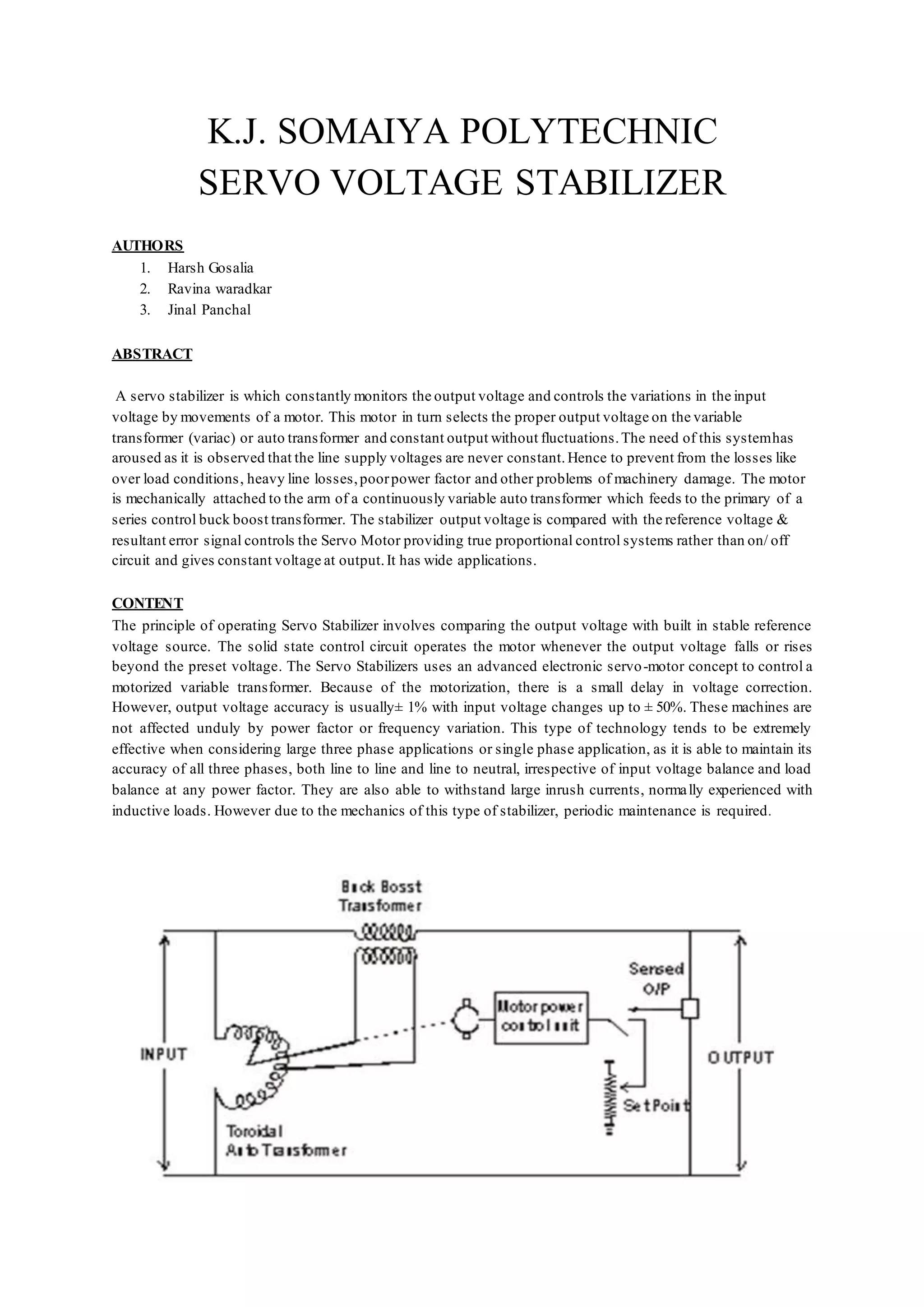
A servo voltage stabilizer uses a servo motor mechanism to continuously sense and monitor output voltage. It compares the output to a reference voltage and uses an error amplifier and motor driver circuit to control a servo motor coupled to an auto transformer. This allows the auto transformer to adjust the output voltage as needed to maintain a constant voltage, compensating for fluctuations in the input voltage. Servo stabilizers can maintain output voltages within 1% for input voltage variations of up to 50% and are useful for applications requiring stable voltage like industrial equipment, medical devices, and laboratories.