Downloaded 18 times
![International Journal of Mechanical Engineering and Technology (IJMET), ISSN 0976 –
6340(Print), ISSN 0976 – 6359(Online), Volume 5, Issue 2, February (2014), pp. 17-25, © IAEME
17
SENSITIVITY ANALYSIS OF HEAT RECOVERY STEAM GENERATOR
FOR A GE 6FA GAS TURBINE
S.Naga Kishorea
, Dr. T.V.Raob
a, b
Department of Mechanical Engineering, DBS Institute of Technology, Kavali-524201
ABSTRACT
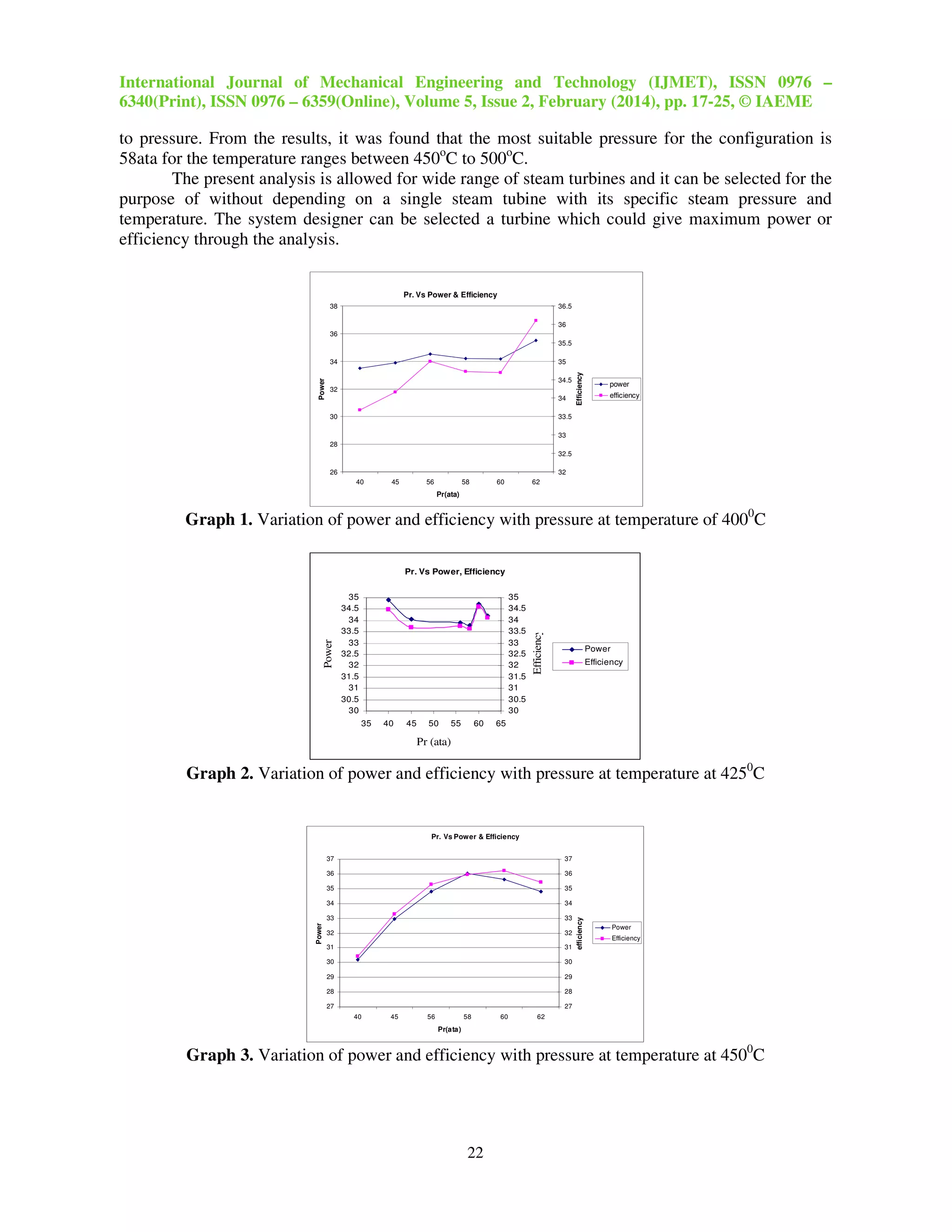
The objective of the present study is to optimize the bottoming cycle for a 6 FA gas turbine.
The present work focuses on optimization of steam cycle alone by analyzing the sensitivity of steam
pressure and steam temperature and configuration of waste heat recovery boiler. A two pressure
configuration will have better opportunity for power generation and for applying service steam for
feed stack and drying etc. From cycle analysis at 4 kg/cm2
low pressure steam appear to be most
suitable for the thermodynamic cycle. Also from the analysis of various configurations a two
pressure steam cycle was chosen with integrated deaerator. Both low temperature and intermediate
pressure were used to extract maximum heat from the gas turbine exhaust. A fixed 2% blow down
steam was assumed as per the industrial practice. Two super heater sections were introduced with a
desuperheater to minimize the energy loss. The temperature of the high pressure steam was kept at
5000
c and the pressure of steam has varied to calculate the variation of power and efficiency. And
also keeping the steam temperature at 4000
C, 4500
C. The power and efficiency at different pressures
ranging from 40 ata to 62 ata were calculated to get an operating point and to allow the steam turbine
designer to have suitable pressure and temperature variation to select the appropriate steam turbine at
bottom cycle.
Keywords: Combined Cycle (Cc), HRSG, Efficiency, NTU, Off Design, Effectiveness.
INTRODUCTION
The gas/steam combined cycle has already become a well-proven and important technology
for power generation due to its numerous advantages. The advantages include its high efficiency in
utilizing energy resources, low environmental emissions, short duration of construction, low initial
investment cost, low operation and maintenance cost, and flexibility in fuel selection, etc.[11]. These
features justify the fact that the combined cycle power plants are quite competitive in the power
market.
INTERNATIONAL JOURNAL OF MECHANICAL ENGINEERING
AND TECHNOLOGY (IJMET)
ISSN 0976 – 6340 (Print)
ISSN 0976 – 6359 (Online)
Volume 5, Issue 2, February (2014), pp. 17-25
© IAEME: www.iaeme.com/ijmet.asp
Journal Impact Factor (2014): 3.8231 (Calculated by GISI)
www.jifactor.com
IJMET
© I A E M E](https://image.slidesharecdn.com/30120140502003-160217065922/75/SENSITIVITY-ANALYSIS-OF-HEAT-RECOVERY-STEAM-GENERATOR-FOR-A-GE-6FA-GAS-TURBINE-1-2048.jpg)
![International Journal of Mechanical Engineering and Technology (IJMET), ISSN 0976 –
6340(Print), ISSN 0976 – 6359(Online), Volume 5, Issue 2, February (2014), pp. 17-25, © IAEME
18
The heat recovery steam generator (HRSG) is the component of the bottoming steam cycle,
which absorbs energy of exhaust gas of the gas turbine and produces steam at subcritical pressures
suitable for the process or for further electricity generation by a steam turbine. Power plant engineers
can design their own HRSGs and the bottoming steam cycles at the initial stage. On the other hand,
gas turbine is not made in order and steam turbine is selected according to the condition of the steam
delivered from a HRSG. In this respect, the design of a HRSG is indispensable to the improvement
of the overall system efficiency and power output, and to the reduction of the main equipment cost
[5, 8, 9]. HRSGs are classified into single, dual, and triple pressure types depending on the number
of drums in the boiler. Dual pressure HRSGs have been widely used because they showed higher
efficiency than single pressure systems and lower investment cost than triple pressure HRSGs.
Murad A Rahim et al studied three types of HRSG and worked on the effects of HRSG design to the
net power generation and overall efficiency of the cycle was performed. Steam pressure, pinch point
temperature difference and approach temperature difference were taken as variables [1]. Meeta
Sharma and Onkar Singh presented a detailed mathematical modeling and analysis for segmented fin
in the HRSG for its various sub-components. The optimization was also done on the basis of
maximum heat recovery with minimum pressure drop for a given heat flow [2]. P.Ravindra Kumar
and V.Dhana Raju studied the operating characteristics of triple pressure reheat HRSGs which were
analyzed. The effects of the configuration of HP superheater and reheater on the thermal
performance and economics of the plant were investigated. The arrangement of Intermediate-
Temperature components such as intermediate pressure (IP) superheater, HP economizer, and low
pressure (LP) superheater were changed to check its effect on the performance of a steam turbine.
The off-design performance was also examined considering the operating ranges of the plant [3].
Mustafa Zeki Yilmazoglu and Ehsan Amirabedin carried out exergy analysis of a combined cycle
gas turbine (CCGT) power plant, in Ankara, in an exergy aspect. The exergy efficiency of each
component and overall plant was studied by calculating exergy destructions and sensitivity analysis
was performed by changing some critical parameters of the system [4]. C.Casarosa and Franco
investigated the thermodynamic analysis to design the operating parameters for the various
configurations of HRSG systems to minimize Exergy losses, taking into account only the
irreversibility due to the temperature difference between the hot and cold streams (pressure drop not
accounting). All the solutions lead to the zero pinch point and infinite heat transfer surface [7].
T.Srinivas projected thermodynamic modelling and optimization of a dual pressure reheating HRSG
in the CC with a deaerator. The variations in CC performance were plotted with the compressor
pressure ratio, gas turbine inlet temperature, HRSG HP, steam reheat pressure and deaerator
pressure. From this study of thermodynamic modelling, the optimized conditions to air compressor,
HP steam, LP steam, steam reheater and deaerator were developed [13].
In this study, sensitivity analysis of a heat recovery steam generator in a combined cycle gas turbine
(CCGT) power plant for GE 6FA Gas Turbine is performed. The power and efficiency at different
pressures ranging from 40 ata to 62 ata are calculated by varying temperatures of steam from 400o
C
to 500o
C for getting an operating point and for allowing the steam turbine designer to have suitable
pressure and temperature variation to select the appropriate steam turbine at bottom cycle.
PLANT DESCRIPTION
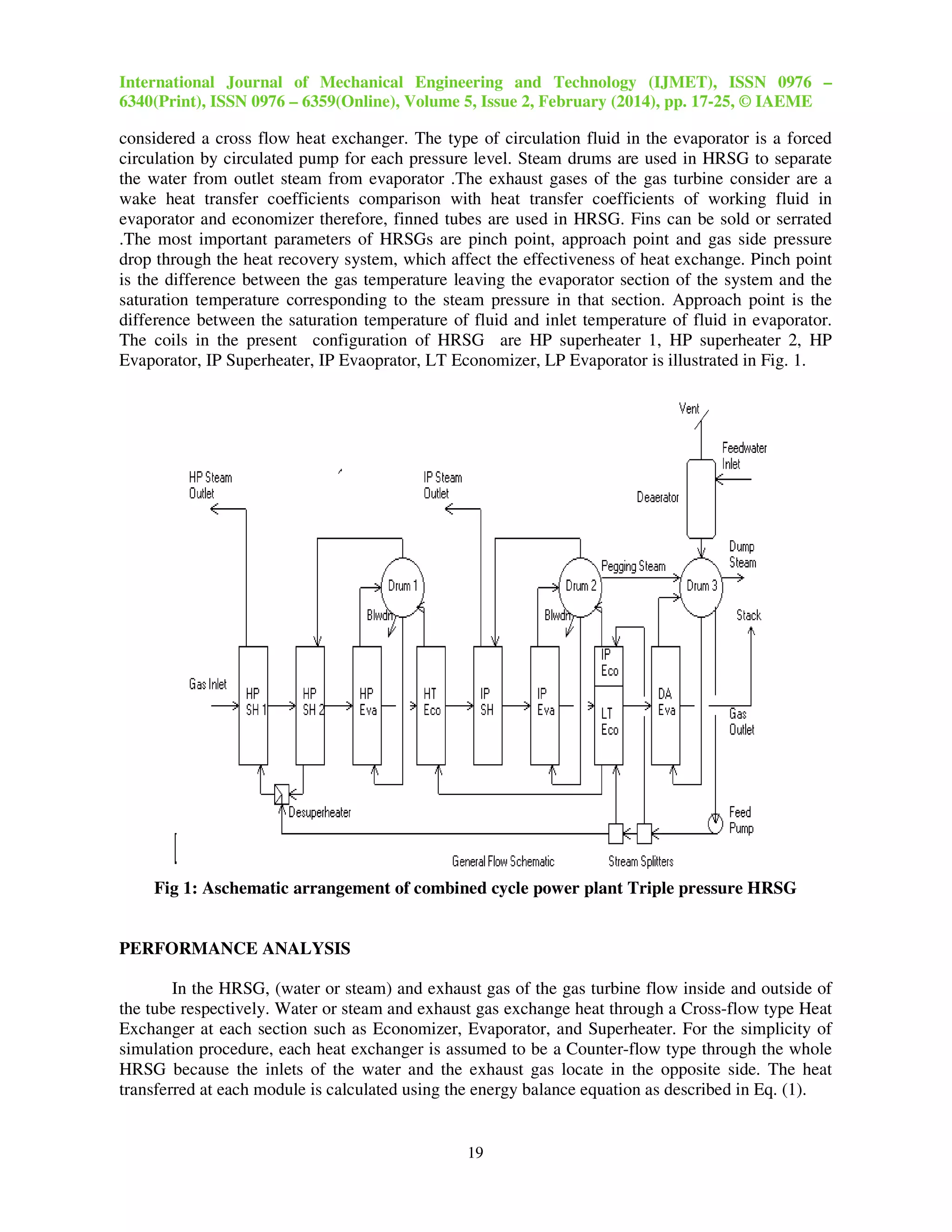
The heat recovery steam generator is a series of heat exchangers. It consists of three heat
exchangers (economizer, evaporator, superheater) for every pressure level. Economizers are used to
heat water close to saturation, evaporators to produce saturated steam and superheaters to produce
superheated steam. Every heat exchanger is a bundle tubes placed in-line or staggered arrangement
according to the manufacture. The flow of working fluid (water or steam) in the pipes is horizontal
flow and the flow of exhaust is vertical flow that's mean, each heat exchanger in the HRSG could be](https://image.slidesharecdn.com/30120140502003-160217065922/75/SENSITIVITY-ANALYSIS-OF-HEAT-RECOVERY-STEAM-GENERATOR-FOR-A-GE-6FA-GAS-TURBINE-2-2048.jpg)
![International Journal of Mechanical Engineering and Technology (IJMET), ISSN 0976 –
6340(Print), ISSN 0976 – 6359(Online), Volume 5, Issue 2, February (2014), pp. 17-25, © IAEME
20
----------(1)
The gas side and water/steam side temperatures at the inlet and outlet of each section of the
HRSG are determined using this energy balance equation Using the well Known effectiveness –NTU
method with overall heat transfer coefficient, Udesign, the area of HRSG together with other related
parameters is calculated based on design parameters shown in equation
---------------(2)
Q max is the maximum heat transfer rate that could possibly be delivered by the heat
exchanger [12].
The heat transfer area can be evaluated with the fin geometry data, and this area should match
the one determined by the effectiveness-NTU method as above. Through the iterative procedure, the
area is determined when the one equals to the other within a prescribed criterion.
Off-design performance analysis of the HRSG [6] is carried out using the design parameters
described as above. The procedure to determine the thermodynamic properties at each section (T, p ,
h ) is repeated until the parameters converge to the assumed value. For illustration, the NTU at off-
design operation is given by Eq. (3).
----------------(3)
Then, we can determine effectiveness as a function of NTU and actual heat transfer rate, as in
Eq. (4). Also we can determine thermodynamic properties such as temperature, pressure, and
enthalpy at each heat exchanger during off-design operation.
-----------------(4)
Off-design performance of gas turbine is estimated with the gas turbine performance curves.
Steam turbine is assumed to operate on the sliding pressure mode during off-design operation.
Performance of each section of steam turbine is analyzed using the well-known
Spencer/Cotton/Cannon correlations [10]
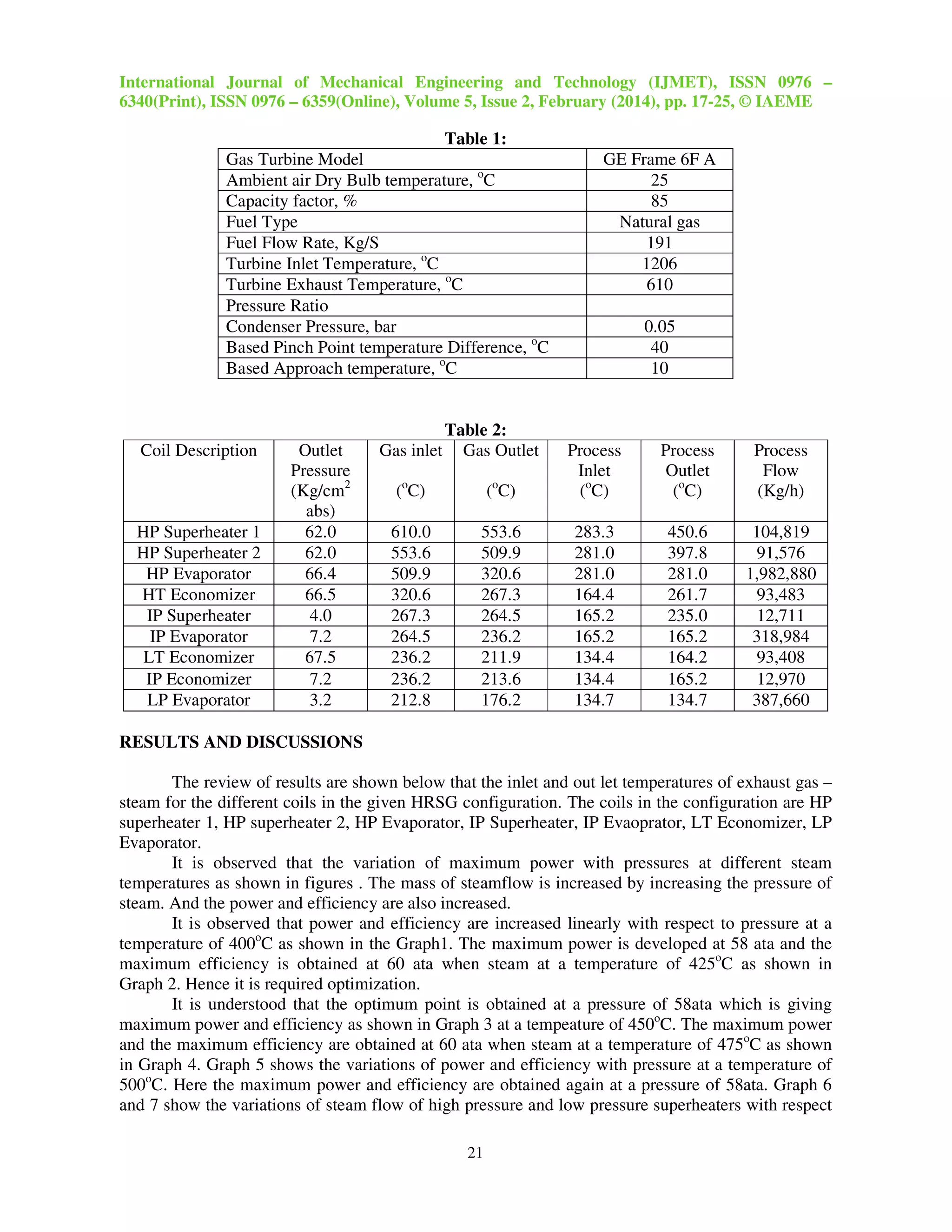
Design conditions such as atmospheric conditions and cycle parameters are shown in Table 1.
At this working condition, the exhaust gas of gas turbine is 687,747 kg/hr in flow rate and 610°C in
temperature, which is suitable for the conventional steam turbine. The total heat transfer area of heat
exchangers is found 21971.1263 m2
. Mass flow rate, absolute pressure and temperature of various
heat exchangers are shown in Table 2.](https://image.slidesharecdn.com/30120140502003-160217065922/75/SENSITIVITY-ANALYSIS-OF-HEAT-RECOVERY-STEAM-GENERATOR-FOR-A-GE-6FA-GAS-TURBINE-4-2048.jpg)
![International Journal of Mechanical Engineering and Technology (IJMET), ISSN 0976 –
6340(Print), ISSN 0976 – 6359(Online), Volume 5, Issue 2, February (2014), pp. 17-25, © IAEME
24
Graph 7. Variation of steam flow of low pressure superheater steam
CONCLUSIONS
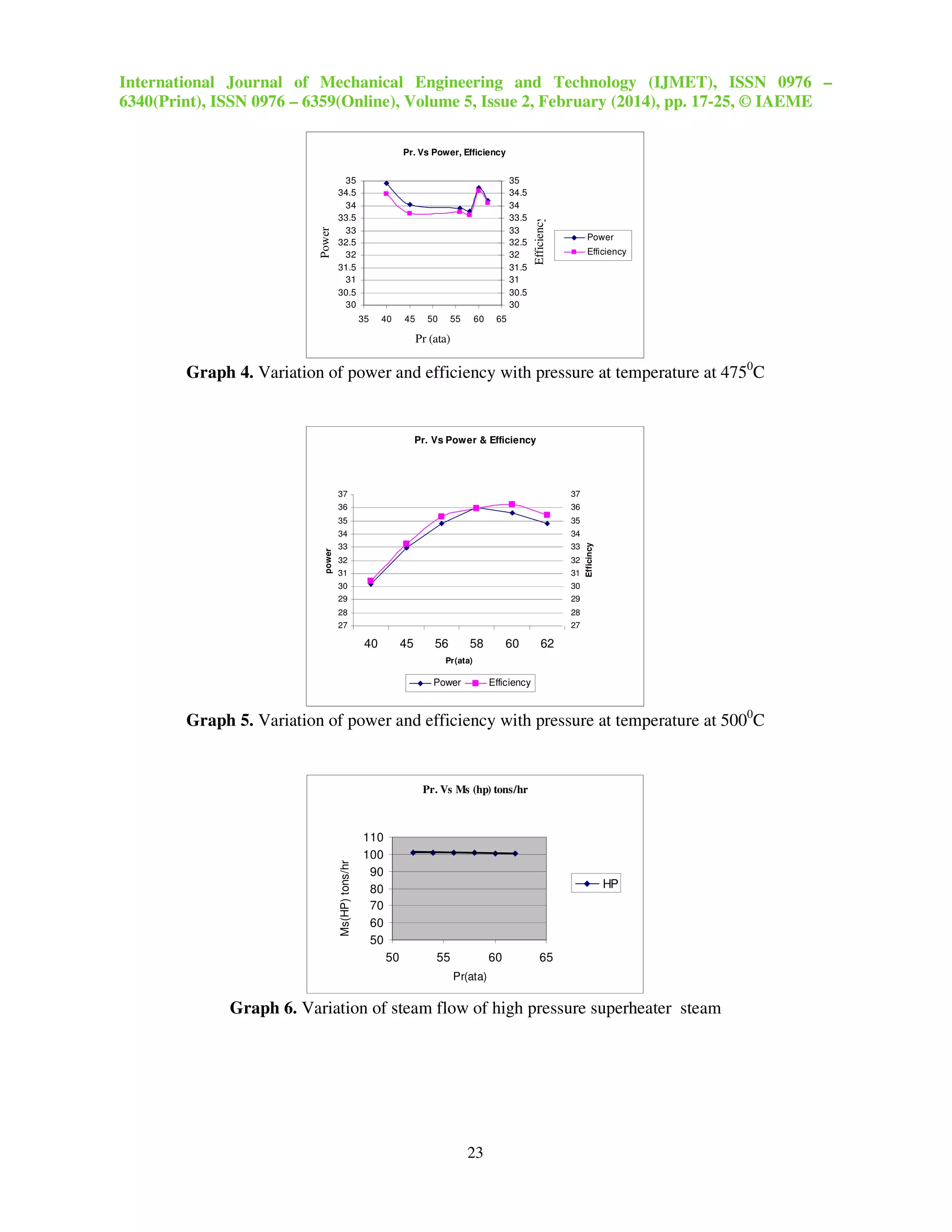
1) From the sensitivity analysis it was found that most suitable pressure appears to be at 58 ata
and steam temperature between 450o
Cand 500o
c will be adequate to give for 100MW power
output and system efficiency around 35% which is on the higher side for that rating. Avoiding
reheating the system cycle configuration was kept crucial.
2) The present analysis allows a wide range of steam turbine that can be selected for the purpose
with out depending on a single steam turbine with its specific steam pressure and temperature.
Through the analysis the system designer select a turbine which could give maximum power
or efficiency.
3) The detailed mechanical design also carried out which provides a reasonable size for the waste
recovery boiler. Two pressure steam not only gives higher power using injection in steam
turbine but also if required provide service steam for drying and process requirement.
4) BHEL manufactures 6 FA gas turbine under license, 6 FA was selected because it was locally
manufactured is having higher efficiency. This is mostly suitable for IGCC plant. It can also to
be noted that the work carried out at so much work for burning low Btu gas such as coal gas
generated in fluidized bed using air whose calorific value is limited to be about 1000 kcal/kg.
Low Btu gas increases the pressure drop in combustion chamber and requires modification for
combustion stability and also air fuel ratio to maintain same entry turbine temperature as
desired, inspite of 7 to 8 times low calorific value has been introduced in the combustion
chamber. This requires modification of gas feeding system, blade cooling concept as well as
fuel gas controlling system.
REFERENCES
[1] Murad A.Rahim, Eshan Amirabedin, M.Zeki Yilmazoglu and “Ali Durmaz, Analysis of Heat
Recovery Steam generators in Combined Cycle Power Plants,” The Second International
conference on Nuclear and Renewable Energy Resources, 4-7 July 2012, Ankara Turkey.
[2] Meeta Sharma, Onkar Singh, “Thermodynamic Evaluation of WHRB for it’s Optimum
performance in Combined Cycle Power Plants,” IOSR Journal of Engineering (IOSRJEN),
Vol. 2 Issue 1, pp. 11-19, Jan.2012.
[3] P.Ravindra Kumar and V.Dhana Raju, 2012, “Off Design Performance Analysis of a Triple
Pressure Reheat Heat Recovery Steam Generator,” International Journal of Engineering
Research & Technology (IJERT) ,Vol. 1 Issue 5, pp. 01-10,July – 2012.
Pr. Vs Ms(IP)
9.5
9.9
10.3
10.7
11.1
11.5
0 20 40 60 80
Pr(ata)
Ms(IP)tons/hr](https://image.slidesharecdn.com/30120140502003-160217065922/75/SENSITIVITY-ANALYSIS-OF-HEAT-RECOVERY-STEAM-GENERATOR-FOR-A-GE-6FA-GAS-TURBINE-8-2048.jpg)
![International Journal of Mechanical Engineering and Technology (IJMET), ISSN 0976 –
6340(Print), ISSN 0976 – 6359(Online), Volume 5, Issue 2, February (2014), pp. 17-25, © IAEME
25
[4] Mustafa Zeki Yilmazoglu and Ehsan Amirabedin, “Second Law And Sensitivity Analysis Of
A Combined Cycle Power Plant In Turkey,” Journal of Thermal Science and Technology,
pp 41-50, 2011.
[5]. Ganapathy, V., "Heat-Recovery Boiler Design for Cogeneration," Oil & Gas Journal,
Vol. 83, pp. 116-125, 1985.
[6]. Kehlhofer, R., “Combined-Cycle Gas & Steam Turbine Power Plants,” The Fairmont Press,
Inc., Georgia, 1991.
[7]. CASAROSA and A. FRANCO, "Thermodynamic Optimization of the Recovery in
Combined Power Plants,” International Journal on Applied Thermodynamics, Vol.4, issue 1,
pp.43-52, March-2005.
[8]. Manen, A. V., "HRSG Design for Optimum Combined Cycle Performance," ASME Paper
94-GT-278, 1994.
[9]. Pasha, A. and Jolly, S., "Combined Cycle Heat Recovery Steam Generators Optimum
Capabilities and Selection Criteria," Heat Recovery Systems & CHP, Vol. 15, No. 2,
pp. 147-154, 1995.
[10]. Spencer, R. C, Cotton, K. C, and Canon, C.N., "A Method for Predicting the Performance of
Steam Turbine-Generators,” Journal of Engineering for Power, Vol. 85, pp. 249-301, 1963.
[11]. El-Masri, M. A. and Foster-Pegg, R. W., "Design of Gas Turbine Combined Cycle and
Cogeneration Systems," Technical Course Lecture Note of GTPRO, 1996.
[12]. Incropera, F. P. and DeWitt, D. P., “Fundamentals of Heat and Mass Transfer,” 4th ed., John
Wiley & Sons Inc., New York, 1996.
[13] T SRINIVAS, “Thermodynamic modelling and optimization of a dual pressure reheat
combined power cycle,” Indian Academy of Sciences, Sadhana Vol. 35, Part 5, pp. 597–608,
October 2010.
[14] P.S. Jeyalaxmi And Dr.G.Kalivarathan, “CFD Analysis of Turbulence in a Gas Turbine
Combustor with Reference to the Context of Exit Phenomenon” International Journal of
Advanced Research in Engineering & Technology (IJARET), Volume 4, Issue 2, 2013,
pp. 1 - 7, ISSN Print: 0976-6480, ISSN Online: 0976-6499.
[15] Aram Mohammed Ahmed and Dr. Mohammad Tariq, “Thermal Analysis of a Gas Turbine
Power Plant to Improve Performance Efficiency”, International Journal of Mechanical
Engineering & Technology (IJMET), Volume 4, Issue 6, 2013, pp. 43 - 54, ISSN Print: 0976
– 6340, ISSN Online: 0976 – 6359,](https://image.slidesharecdn.com/30120140502003-160217065922/75/SENSITIVITY-ANALYSIS-OF-HEAT-RECOVERY-STEAM-GENERATOR-FOR-A-GE-6FA-GAS-TURBINE-9-2048.jpg)

This study analyzes the heat recovery steam generator (HRSG) for a GE 6FA gas turbine, focusing on optimizing the bottoming cycle by examining the effects of steam pressure, temperature, and waste heat recovery boiler configurations. Results reveal that a dual pressure steam cycle is optimal, with maximum power and efficiency observed at a steam pressure of 58 ata across various steam temperatures. The analysis provides valuable insights for steam turbine designers regarding suitable operational parameters for enhanced power generation.


![Seller Deck - Presentation [Concert L2].PPTX](https://cdn.slidesharecdn.com/ss_thumbnails/sellerdeck-presentationconcertl2-251219171156-24982daf-thumbnail.jpg?width=640&height=640&fit=bounds)


