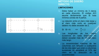
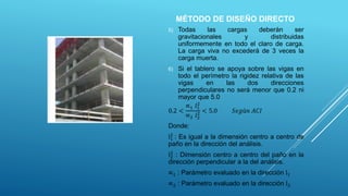
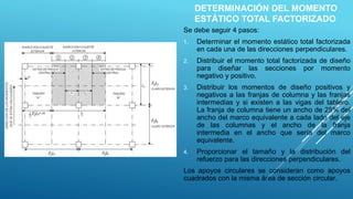
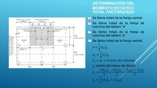
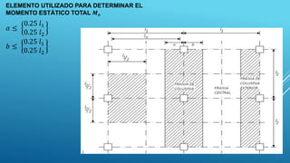
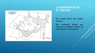
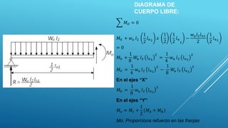
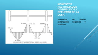
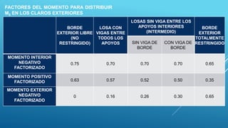
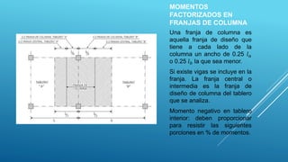
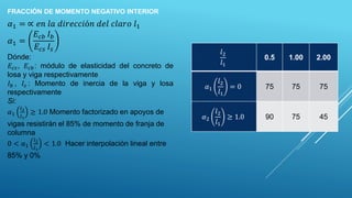
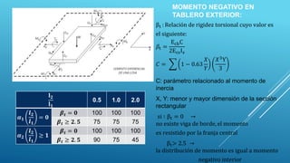
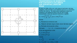
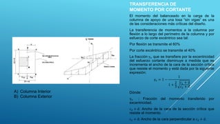
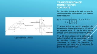
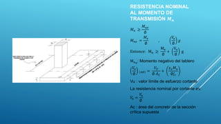
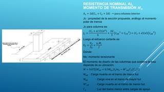
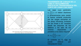
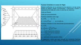
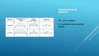
This document discusses the direct design method for reinforced concrete slabs. It outlines several limitations of the method and provides steps for determining the factored total bending moment. These include distributing the design moments to slab sections and reinforcing for negative and positive moments. Equations are given for calculating the factored bending moments distributed to column strips, intermediate strips, and exterior slab regions. Factors that influence moment distribution like relative stiffness of beams and slabs are also presented.
Aquí se estudian y deducen las relaciones entre el momento flexionante y los esfuerzos normales por flexión que se producen, y entre fuerzas cortantes verticales y los esfuerzos cortantes, y asimismo, diversos temas de importancia práctica en el diseño de vigas.
Torsión se refiere al torcimiento de una barra recta al ser cargada por momentos (o pares de torsión) que tienden a producir rotación con respecto al eje longitudinal de la barra.
manual del sap2000 para poder verificar los esfuerzos que se generan a partir de fuerzas externas u internas.
se podrá ver: los momentos flexionares - las fuerzas cortantes
this slide will clear all the topics and problem related to singly reinforced beam by limit state method, things are explained with diagrams , easy to understand .
All reinforced concrete beams crack, generally starting at loads well below service level, and possibly even prior to loading due to restrained shrinkage. Flexural cracking due to loads is not only inevitable, but actually necessary for the reinforcement to be used effectively. Prior to the formation of flexural cracks, the steel stress is no more than n times the stress in the adjacent concrete, where n is the modular ratio E5/Ec. For materials common in current practice, n is approximately 8.
This document presents an example of analysis design of slab using ETABS. This example examines a simple single story building, which is regular in plan and elevation. It is examining and compares the calculated ultimate moment from CSI ETABS & SAFE with hand calculation. Moment coefficients were used to calculate the ultimate moment. However it is good practice that such hand analysis methods are used to verify the output of more sophisticated methods.
Also, this document contains simple procedure (step-by-step) of how to design solid slab according to Eurocode 2.The process of designing elements will not be revolutionised as a result of using Eurocode 2. Due to time constraints and knowledge, I may not be able to address the whole issues.
Cosmetic shop management system project report.pdfKamal Acharya
Buying new cosmetic products is difficult. It can even be scary for those who have sensitive skin and are prone to skin trouble. The information needed to alleviate this problem is on the back of each product, but it's thought to interpret those ingredient lists unless you have a background in chemistry.
Instead of buying and hoping for the best, we can use data science to help us predict which products may be good fits for us. It includes various function programs to do the above mentioned tasks.
Data file handling has been effectively used in the program.
The automated cosmetic shop management system should deal with the automation of general workflow and administration process of the shop. The main processes of the system focus on customer's request where the system is able to search the most appropriate products and deliver it to the customers. It should help the employees to quickly identify the list of cosmetic product that have reached the minimum quantity and also keep a track of expired date for each cosmetic product. It should help the employees to find the rack number in which the product is placed.It is also Faster and more efficient way.
Event Management System Vb Net Project Report.pdfKamal Acharya
In present era, the scopes of information technology growing with a very fast .We do not see any are untouched from this industry. The scope of information technology has become wider includes: Business and industry. Household Business, Communication, Education, Entertainment, Science, Medicine, Engineering, Distance Learning, Weather Forecasting. Carrier Searching and so on.
My project named “Event Management System” is software that store and maintained all events coordinated in college. It also helpful to print related reports. My project will help to record the events coordinated by faculties with their Name, Event subject, date & details in an efficient & effective ways.
In my system we have to make a system by which a user can record all events coordinated by a particular faculty. In our proposed system some more featured are added which differs it from the existing system such as security.
Hybrid optimization of pumped hydro system and solar- Engr. Abdul-Azeez.pdffxintegritypublishin
Advancements in technology unveil a myriad of electrical and electronic breakthroughs geared towards efficiently harnessing limited resources to meet human energy demands. The optimization of hybrid solar PV panels and pumped hydro energy supply systems plays a pivotal role in utilizing natural resources effectively. This initiative not only benefits humanity but also fosters environmental sustainability. The study investigated the design optimization of these hybrid systems, focusing on understanding solar radiation patterns, identifying geographical influences on solar radiation, formulating a mathematical model for system optimization, and determining the optimal configuration of PV panels and pumped hydro storage. Through a comparative analysis approach and eight weeks of data collection, the study addressed key research questions related to solar radiation patterns and optimal system design. The findings highlighted regions with heightened solar radiation levels, showcasing substantial potential for power generation and emphasizing the system's efficiency. Optimizing system design significantly boosted power generation, promoted renewable energy utilization, and enhanced energy storage capacity. The study underscored the benefits of optimizing hybrid solar PV panels and pumped hydro energy supply systems for sustainable energy usage. Optimizing the design of solar PV panels and pumped hydro energy supply systems as examined across diverse climatic conditions in a developing country, not only enhances power generation but also improves the integration of renewable energy sources and boosts energy storage capacities, particularly beneficial for less economically prosperous regions. Additionally, the study provides valuable insights for advancing energy research in economically viable areas. Recommendations included conducting site-specific assessments, utilizing advanced modeling tools, implementing regular maintenance protocols, and enhancing communication among system components.
COLLEGE BUS MANAGEMENT SYSTEM PROJECT REPORT.pdfKamal Acharya
The College Bus Management system is completely developed by Visual Basic .NET Version. The application is connect with most secured database language MS SQL Server. The application is develop by using best combination of front-end and back-end languages. The application is totally design like flat user interface. This flat user interface is more attractive user interface in 2017. The application is gives more important to the system functionality. The application is to manage the student’s details, driver’s details, bus details, bus route details, bus fees details and more. The application has only one unit for admin. The admin can manage the entire application. The admin can login into the application by using username and password of the admin. The application is develop for big and small colleges. It is more user friendly for non-computer person. Even they can easily learn how to manage the application within hours. The application is more secure by the admin. The system will give an effective output for the VB.Net and SQL Server given as input to the system. The compiled java program given as input to the system, after scanning the program will generate different reports. The application generates the report for users. The admin can view and download the report of the data. The application deliver the excel format reports. Because, excel formatted reports is very easy to understand the income and expense of the college bus. This application is mainly develop for windows operating system users. In 2017, 73% of people enterprises are using windows operating system. So the application will easily install for all the windows operating system users. The application-developed size is very low. The application consumes very low space in disk. Therefore, the user can allocate very minimum local disk space for this application.
Sachpazis:Terzaghi Bearing Capacity Estimation in simple terms with Calculati...Dr.Costas Sachpazis
Terzaghi's soil bearing capacity theory, developed by Karl Terzaghi, is a fundamental principle in geotechnical engineering used to determine the bearing capacity of shallow foundations. This theory provides a method to calculate the ultimate bearing capacity of soil, which is the maximum load per unit area that the soil can support without undergoing shear failure. The Calculation HTML Code included.
Student information management system project report ii.pdfKamal Acharya
Our project explains about the student management. This project mainly explains the various actions related to student details. This project shows some ease in adding, editing and deleting the student details. It also provides a less time consuming process for viewing, adding, editing and deleting the marks of the students.
Courier management system project report.pdfKamal Acharya
It is now-a-days very important for the people to send or receive articles like imported furniture, electronic items, gifts, business goods and the like. People depend vastly on different transport systems which mostly use the manual way of receiving and delivering the articles. There is no way to track the articles till they are received and there is no way to let the customer know what happened in transit, once he booked some articles. In such a situation, we need a system which completely computerizes the cargo activities including time to time tracking of the articles sent. This need is fulfilled by Courier Management System software which is online software for the cargo management people that enables them to receive the goods from a source and send them to a required destination and track their status from time to time.
Automobile Management System Project Report.pdfKamal Acharya
The proposed project is developed to manage the automobile in the automobile dealer company. The main module in this project is login, automobile management, customer management, sales, complaints and reports. The first module is the login. The automobile showroom owner should login to the project for usage. The username and password are verified and if it is correct, next form opens. If the username and password are not correct, it shows the error message.
When a customer search for a automobile, if the automobile is available, they will be taken to a page that shows the details of the automobile including automobile name, automobile ID, quantity, price etc. “Automobile Management System” is useful for maintaining automobiles, customers effectively and hence helps for establishing good relation between customer and automobile organization. It contains various customized modules for effectively maintaining automobiles and stock information accurately and safely.
When the automobile is sold to the customer, stock will be reduced automatically. When a new purchase is made, stock will be increased automatically. While selecting automobiles for sale, the proposed software will automatically check for total number of available stock of that particular item, if the total stock of that particular item is less than 5, software will notify the user to purchase the particular item.
Also when the user tries to sale items which are not in stock, the system will prompt the user that the stock is not enough. Customers of this system can search for a automobile; can purchase a automobile easily by selecting fast. On the other hand the stock of automobiles can be maintained perfectly by the automobile shop manager overcoming the drawbacks of existing system.
Explore the innovative world of trenchless pipe repair with our comprehensive guide, "The Benefits and Techniques of Trenchless Pipe Repair." This document delves into the modern methods of repairing underground pipes without the need for extensive excavation, highlighting the numerous advantages and the latest techniques used in the industry.
Learn about the cost savings, reduced environmental impact, and minimal disruption associated with trenchless technology. Discover detailed explanations of popular techniques such as pipe bursting, cured-in-place pipe (CIPP) lining, and directional drilling. Understand how these methods can be applied to various types of infrastructure, from residential plumbing to large-scale municipal systems.
Ideal for homeowners, contractors, engineers, and anyone interested in modern plumbing solutions, this guide provides valuable insights into why trenchless pipe repair is becoming the preferred choice for pipe rehabilitation. Stay informed about the latest advancements and best practices in the field.
Overview of the fundamental roles in Hydropower generation and the components involved in wider Electrical Engineering.
This paper presents the design and construction of hydroelectric dams from the hydrologist’s survey of the valley before construction, all aspects and involved disciplines, fluid dynamics, structural engineering, generation and mains frequency regulation to the very transmission of power through the network in the United Kingdom.
Author: Robbie Edward Sayers
Collaborators and co editors: Charlie Sims and Connor Healey.
(C) 2024 Robbie E. Sayers
Forklift Classes Overview by Intella PartsIntella Parts
Discover the different forklift classes and their specific applications. Learn how to choose the right forklift for your needs to ensure safety, efficiency, and compliance in your operations.
For more technical information, visit our website https://intellaparts.com
1. UNIVERSIDAD NACIONAL JOSÉ FAUSTINO
SÁNCHEZ CARRIÓN
FACULTAD DE INGENIERÍA CIVIL
ESCUELA PROFESIONAL DE INGENIERÍA CIVIL
SETIEMBRE 2021
CURSO: Concreto Armado II
TEMA: Método de diseño directo
2. MÉTODO DE DISEÑO
DIRECTO
LIMITACIONES
1) Debe haber un mínimo de 3 claros
en cada dirección. El código ACI
asume tácitamente que la losa
mínima consta de 9 paños.
2) La relación entre el claro más largo y
el claro más corto en cualquier
tablero no debe exceder de 2.
Si B > A =>
B
A
< 2
3) Las longitudes de los claros
sucesivos en cada dirección no
deben exceder más de 1/3 del claro
más largo.
4) La excentricidad máxima de las
columnas con relación a cualquiera
de los dos ejes que unen a columnas
sucesivas no excederá el 10% del
claro en la dirección de la
excentricidad.
3. 5) Todas las cargas deberán ser
gravitacionales y distribuidas
uniformemente en todo el claro de carga.
La carga viva no excederá de 3 veces la
carga muerta.
6) Si el tablero se apoya sobre las vigas en
todo el perímetro la rigidez relativa de las
vigas en las dos direcciones
perpendiculares no será menor que 0.2 ni
mayor que 5.0
0.2 <
∝1 𝑙1
2
∝2 𝑙2
2 < 5.0 𝑆𝑒𝑔ú𝑛 𝐴𝐶𝐼
Donde:
l1
2
: Es igual a la dimensión centro a centro de
paño en la dirección del análisis.
l2
2
: Dimensión centro a centro del paño en la
dirección perpendicular a la del análisis.
∝1 : Parámetro evaluado en la dirección l1
∝2 : Parámetro evaluado en la dirección l2
MÉTODO DE DISEÑO DIRECTO
4. DETERMINACIÓN DEL MOMENTO
ESTÁTICO TOTAL FACTORIZADO
Se debe seguir 4 pasos:
1. Determinar el momento estático total factorizada
en cada una de las direcciones perpendiculares.
2. Distribuir el momento total factorizada de diseño
para diseñar las secciones por momento
negativo y positivo.
3. Distribuir los momentos de diseño positivos y
negativos a las franjas de columna y las franjas
intermedias y si existen a las vigas del tablero.
La franja de columna tiene un ancho de 25% del
ancho del marco equivalente a cada lado del eje
de las columnas y el ancho de la franja
intermedia en el ancho que sería del marco
equivalente.
4. Proporcionar el tamaño y la distribución del
refuerzo para las direcciones perpendiculares.
Los apoyos circulares se consideran como apoyos
cuadrados con la misma área de sección circular.
5. DETERMINACIÓN DEL
MOMENTO ESTÁTICO
TOTAL FACTORIZADO
Se llama mitad de la franja central
Se llama mitad de la franja de
columna del tablero “a”
Se llama mitad de la franja de
columna del tablero “b”
Se llama mitad de la franja central.
x =
1
4
𝑙2 𝑎
𝑥1 =
1
4
𝑙2 𝑏
𝑥1 + 𝑥2 = 𝐹𝑟𝑎𝑛𝑗𝑎 𝑑𝑒 𝑐𝑜𝑙𝑢𝑚𝑛𝑎
l2: ancho del marco de diseño.
𝑙2 =
1 𝑙2 𝑎
2
+
1 𝑙2 𝑏
2
=
𝑙2 𝑎 + 𝑙2 𝑏
2
𝑙2 =
1
2
𝑙2 𝑎 + 𝑙2 𝑏
1
2
3
4
6. ELEMENTO UTILIZADO PARA DETERMINAR EL
MOMENTO ESTÁTICO TOTAL 𝑴𝒐
𝑎 ≤
0.25 𝑙1
0.25 𝑙2
𝑏 ≤
0.25 𝑙1
0.25 𝑙2
7. LOS MOMENTOS EN
EL TABLERO
Wu: carga última por unidad
de área
Mo: momento simple que
actúa en el tablero interior de
una losa en 2 direcciones.
10. FACTORES DEL MOMENTO PARA DISTRIBUIR
M0 EN LOS CLAROS EXTERIORES
BORDE
EXTERIOR LIBRE
(NO
RESTRINGIDO)
LOSA CON
VIGAS ENTRE
TODOS LOS
APOYOS
LOSAS SIN VIGA ENTRE LOS
APOYOS INTERIORES
(INTERMEDIO)
BORDE
EXTERIOR
TOTALMENTE
RESTRINGIDO
SIN VIGA DE
BORDE
CON VIGA DE
BORDE
MOMENTO INTERIOR
NEGATIVO
FACTORIZADO
0.75 0.70 0.70 0.70 0.65
MOMENTO POSITIVO
FACTORIZADO 0.63 0.57 0.52 0.50 0.35
MOMENTO EXTERIOR
NEGATIVO
FACTORIZADO
0 0.16 0.26 0.30 0.65
11. MOMENTOS
FACTORIZADOS EN
FRANJAS DE COLUMNA
Una franja de columna es
aquella franja de diseño que
tiene a cada lado de la
columna un ancho de 0.25 𝑙𝑎
o 0.25 𝑙𝑏 la que sea menor.
Si existe vigas se incluye en la
franja. La franja central o
intermedia es la franja de
diseño de columna del tablero
que se analiza.
Momento negativo en tablero
interior: deben proporcionar
para resistir las siguientes
porciones en % de momentos.
12. FRACCIÓN DE MOMENTO NEGATIVO INTERIOR
𝛼1 = ∝ 𝑒𝑛 𝑙𝑎 𝑑𝑖𝑟𝑒𝑐𝑐𝑖ó𝑛 𝑑𝑒𝑙 𝑐𝑙𝑎𝑟𝑜 𝑙1
𝛼1 =
𝐸𝑐𝑏 𝐼𝑏
𝐸𝑐𝑠 𝐼𝑠
Dónde:
𝐸𝑐𝑠, 𝐸𝑐𝑏: módulo de elasticidad del concreto de
losa y viga respectivamente
𝐼𝑏 , 𝐼𝑠 : Momento de inercia de la viga y losa
respectivamente
Si:
𝛼1
𝑙2
𝑙1
≥ 1.0 Momento factorizado en apoyos de
vigas resistirán el 85% de momento de franja de
columna
0 < 𝛼1
𝑙2
𝑙1
< 1.0 Hacer interpolación lineal entre
85% y 0%
𝑙2
𝑙1
0.5 1.00 2.00
𝛼1
𝑙2
𝑙1
= 0 75 75 75
𝛼2
𝑙2
𝑙1
≥ 1.0 90 75 45
13. MOMENTO NEGATIVO EN
TABLERO EXTERIOR:
βt : Relación de rigidez torsional cuyo valor es
el siguiente:
𝛽t =
EcbC
2EcsIs
𝐶 = 1 − 0.63
𝑋
𝑌
𝑋3Y
3
C: parámetro relacionado al momento de
inercia
X, Y: menor y mayor dimensión de la sección
rectangular
si ∶ βt = 0 →
no existe viga de borde, el momento
es resistido por la franja central
βt> 2.5 →
la distribución de momento es igual a momento
negativo interior
𝐥𝟐
𝐥𝟏
0.5 1.0 2.0
𝜶𝟏
𝒍𝟐
𝒍𝟏
= 𝟎
𝜷𝒕 = 𝟎 100 100 100
𝜷𝒕 ≥ 𝟐. 𝟓 75 75 75
𝜶𝟐
𝒍𝟐
𝒍𝟏
≥ 𝟏
𝜷𝒕 = 𝟎 100 100 100
𝜷𝒕 ≥ 𝟐. 𝟓 90 75 45
14. MOMENTO NEGATIVO
EN TABLERO
EXTERIOR:
Se pueden plantear 6
ecuaciones porque las
mismas son insuficientes para
determinar las fuerzas
interiores, para la solución es
necesario considerar
condiciones de borde.
Para calcular el valor de “C”
se considera una sección “T”.
De estas 2 posibilidades se
toma el mayor valor de “C”
17. EFECTO DE LA HIPÓTESIS DE CARGA
EN INCREMENTO DE LOS MOMENTOS
POSITIVOS.
El reglamento establece que si la relación entre las cargas vivas y
las cargas muertas sin factorizar exceden el valor de 0.5 la
relación de rigidez αc debe ser igual o mayor que la relación de
rigidez mínima.
αc ≥ αmin
Dada en la Tabla N° 01:
Si: 𝛼𝑐 < 𝛼𝑚𝑖𝑛 →
𝑓𝑎𝑐𝑡𝑜𝑟𝑒𝑠 𝑝𝑜𝑠𝑖𝑡𝑖𝑣𝑜𝑠 𝑑𝑒 𝑚𝑜𝑚𝑒𝑛𝑡𝑜𝑠 𝑚𝑢𝑙𝑡𝑖𝑝𝑙𝑖𝑐𝑎𝑟 𝑝𝑜𝑟 𝑓𝑠 > 1.00
δs = 1 +
2 − βa
4 + βa
1 −
αc
αmin
Dónde: δs = factor
βa =
wo
wl
=
CARGA MUERTA SIN FACTORIZAR POR UNIDAD DE ÁREA
CARGA VIVA SIN FACTORIZAR POR UNIDAD DE ÁREA
αc =
SUMA DE LAS RIGIDECES DE LAS COLUMNAS ARRIBA Y ABAJO DE LA LOSA
SUMA DE LAS RIGIDECES DE VIGAS Y LOSAS QUE FORMAN MARCO EN
LA DIRECCION DEL CLARO PARA EL CUAL SE ESTAN DETERMIANDO
LOS MOMENTOS
𝛼𝑐 =
𝐾𝐶
𝐾𝐵 + 𝐾𝑆
∝c ≥ ∝min Relación de rigidez
19. TRANSFERENCIA DE MOMENTOS
POR CORTANTE A COLUMNAS
QUE SOPORTAN LOSAS SIN
VIGAS
El plano de falla crítico por corte sigue el perímetro del área
cargada y está ubicada a una distancia que da a un perímetro
mínimo de corte b0. No debe estar localizada al plano de
cortante a una distancia menor que d/2 de la carga
concentrada o área de reacción (columna o capitel).
𝑉
𝑐 = 0.27
2 + 4
𝛽𝑐
𝑓′
𝑐
𝑏0𝑑 ≤ 1.06 𝑓′𝑐 𝑏0𝑑
Donde:
Vc: Resistencia nominal al corte
βc: Relación del lado mayor al lado menor del área cargada
b0: Perímetro de la sección crítica
Por tanto: Vn < Vc → Condición de diseño
Si se usa especial por corte:
Vn ≤ 1.06 f′c b0d
𝑉
𝑐 ≤ 0.53 𝑓′𝑐 𝑏0𝑑
Donde:
𝑉
𝑐 ≤
𝑉
𝑛
∅
, ∅ = 0.85
𝑉
𝑛 = 𝑤𝑢 𝐴𝐵 − 𝑐1 + 𝑑 𝑐2 + 𝑑 ∅
20. TRANSFERENCIA DE
MOMENTO POR CORTANTE
El momento del balanceado en la carga de la
columna de apoyo de una losa “sin vigas” es una
de las consideraciones más críticas del diseño.
La transferencia de momentos a la columna por
flexión a lo largo del perímetro de la columna y por
esfuerzo de corte excéntrico sea tal:
Por flexión se transmite el 60%
Por corte excéntrico se transmite el 40%
La fracción γv que se transfiere por la excentricidad
del esfuerzo cortante disminuye a medida que se
incrementa el ancho de la cara de la sección crítica
que resiste el momento y está dada por la siguiente
expresión:
𝛾𝑣 = 1 −
1
1 +
2
3
c1 + d
c2 + d
Dónde:
γv : Fracción del momento transferido por
excentricidad.
c2 + d: Ancho de la cara de la sección crítica que
resiste el momento.
c1 + d: Ancho de la cara perpendicular a c2 + d.
A) Columna Interior
B) Columna Exterior
21. TRANSFERENCIA DE
MOMENTO POR
CORTANTE
La fracción remanente del momento
desbalanceado transferido por flexión
está dada por:
𝛾𝑓 = 1 −
1
1 +
2
3
c1 + d
c2 + d
ó γf = 1 − γv
Y actúa sobre un ancho efectivo de
losas entre líneas que están a 15 veces
el espesor total “h” de la losa sobre
ambos lados del apoyo de la columna.
Vu y Mu que actúan en la columna se
debe transferir al eje centroidal c-c de
la sección crítica por eso debe
obtenerse el brazo de palanca “g”
(distancia del paño de la columna al
plano del eje centroidal
C) Superficie Crítica
22. RESISTENCIA NOMINAL
AL MOMENTO DE
TRANSMISIÓN 𝑴𝒏
𝑀𝑛 ≥
𝑀𝑢𝑒
∅
𝑀𝑛𝑒 =
𝑀𝑒
∅
,
𝑉
𝑢
∅
𝑔
Entonce: Mn ≥
Me
∅
+
Vu
∅
g
Mne: Momento negativo del tablero
𝑉
𝑢
∅ 𝐴𝐵 =
𝑉𝑈
∅ 𝐴𝐶
+
𝛾𝑢𝑀𝑢
∅𝐽𝑐
Vu : valor límite de esfuerzo cortante
La resistencia nominal por cortante es:
𝑉
𝑛 =
𝑉
𝑢
∅
Ac : área del concreto de la sección
crítica supuesta
23. RESISTENCIA NOMINAL AL
MOMENTO DE TRANSMISIÓN 𝑴𝒏
Ac = 2d C1 + C2 + 2d → para columna interior
Jc : propiedad de la sección propuesta, análogo al momento
polar de inercia
Jc para columna es:
𝐽𝑐 =
𝐶1 + 𝑑 2 𝑑3
6
+
2𝑑
3
𝐶𝐴𝐵
3
+ 𝐶𝐶𝐷
3
+ 𝐶2 + 𝑑 𝑑 𝐶𝐴𝐵
2
Luego el esfuerzo cortante es:
𝑉𝑈 =
𝑉𝑈
𝐴𝐶
+
𝛾𝑣𝑀𝑐
𝐽
Dónde:
Mc: momento tensionante
El momento de diseño de las columnas que sostiene la losa
depende de su ubicación.
𝑀 = 0.07 𝑊𝑛𝑑 + 0.5𝑊
𝑛𝑒 𝑙2𝑙𝑛2 − 𝑊′𝑛𝑑𝑙′2 𝑙′𝑛
2
Wnd : Carga muerta en el tramo de mayor luz
Wne : Carga viva en el tramo de mayor luz
W′nd : Carga muerta en el tramo de menor luz
l′n : Luz del tramo menor entre cargas de apoyo
24. TRANSMISIÓN DE CARGAS DE LA
LOSA A LOS ELEMENTOS
VERTICALES TRANSFERENCIA DEL
CORTE EN LOSAS CON VIGAS
Las vigas cuyo parámetro
α1
l2
l1
≥ 1.0 deben diseñarse
ó dimensionarse para resistir
la fuerza cortante producida
por las cargas actuantes en
las áreas tributarias limitadas
por las líneas a 45° trazadas
desde las esquinas de los
tableros y los ejes de los
mismos adyacentes y
paralelos a los lados mayores.
𝑆𝑖: ∝1
𝑙2
𝑙1
< 1.0
El cortante en la viga se
puede obtener por
interpolación lineal.
25. Fuerzas Cortantes en Losas sin Vigas
Deberá verificarse en la vecindad de los apoyos y en las zonas
donde se aplican cargas concentradas y reacciones. Existen 2
mecanismos de falla por corte en este tipo de sistemas:
Corte por flexión
Corte por punzonamiento
Fuerzas cortantes como viga
𝑉𝑈 ≤ ∅𝑉
𝑛 ; 𝑉
𝑛 = 𝑉
𝑐
Vc = 0.53 f′cb0d ; d= h-3.00 cm.
Fuerzas cortantes en dos direcciones (punzonamiento)
VU ≤ ∅Vn
𝑉
𝑐 = 0.53 +
1.1
𝛽𝐶
𝑓′𝑐𝑏0𝑑
𝛽𝐶 =
𝐿𝑎𝑑𝑜 𝑙𝑎𝑟𝑔𝑜 𝑑𝑒 𝑙𝑎 𝑐𝑜𝑙𝑢𝑚𝑛𝑎
𝑙𝑎𝑑𝑜 𝑐𝑜𝑟𝑡𝑜 𝑑𝑒 𝑙𝑎 𝑐𝑜𝑙𝑢𝑚𝑛𝑎
𝑉
𝑐 < 1.1 𝑓′𝑐𝑏0𝑑
b0 = perímetro de la sección crítica
El reglamento indica que para calcular los momentos flectores
podrá utilizarse una carga uniforme repartidas equivalentemente.