Contents :-
GeneralRecommendations of the code
Classification of columns
Effective Length of columns & Minimum
eccentricity
Design Moments in Columns
Design
3.
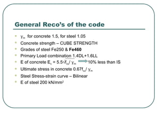
General Reco’s ofthe code
m for concrete 1.5, for steel 1.05
Concrete strength – CUBE STRENGTH
Grades of steel Fe250 & Fe460
Primary Load combination 1.4DL+1.6LL
E of concrete Ec = 5.5√fcu/ m 10% less than IS
Ultimate stress in concrete 0.67fcu/ m
Steel Stress-strain curve – Bilinear
E of steel 200 kN/mm2
4.
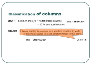
Classification of columns
SHORT– both lex/h and ley/b < 15 for braced columns
< 10 for unbraced columns
BRACED - If lateral stability to structure as a whole is provided by walls
or bracing designed to resist all lateral forces in that plane.
else – SLENDER
Cl.3.8.1.5
else – UNBRACED
5.
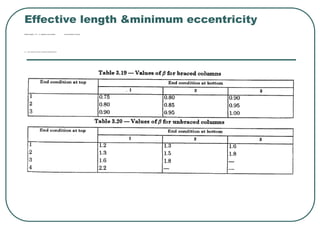
Effective length &minimumeccentricity
Effective length le = ßlo ß – depends on end condition at top and bottom of column.
emin = 0.05 x dimension of column in the plane of bending ≤ 20 mm
6.
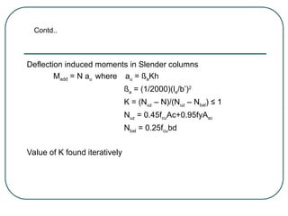
Deflection induced momentsin Slender columns
Madd = N au where au = ßaKh
ßa = (1/2000)(le/b’)2
K = (Nuz – N)/(Nuz – Nbal) ≤ 1
Nuz = 0.45fcuAc+0.95fyAsc
Nbal = 0.25fcubd
Value of K found iteratively
Contd..
7.
Contd..
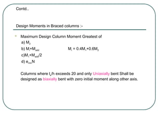
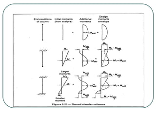
Design Moments inBraced columns :-
Maximum Design Column Moment Greatest of
a) M2
b) Mi+Madd Mi = 0.4M1+0.6M2
c)M1+Madd/2
d) eminN
Columns where le/h exceeds 20 and only Uniaxially bent Shall be
designed as biaxially bent with zero initial moment along other axis.
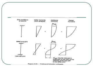
Design Moments inUnBraced columns :-
The additional Moment may be assumed to occur at whichever
end of column has stiffer joint. This stiffer joint may be the
critical section for that column.
Deflection of all UnBraced columns in a storey
auav for all stories = Σ au/n
12.
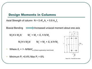
Design Moments inColumns
Axial Strength of column N = 0.4fcuAc + 0.8 Ascfy
Biaxial Bending Increased uniaxial moment about one axis
Mx/h’≥ My/b’ Mx’ = Mx + ß1 h’/b’My
Mx/h’≤ My/b’ My’ = My + ß1 b’/h’Mx
Where ß1 = 1- N/6bhfcu (Check explanatory hand book)
Minimum Pt =0.4% Max Pt = 6%
13.
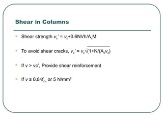
Shear in Columns
Shear strength vc’ = vc+0.6NVh/AcM
To avoid shear cracks, vc’ = vc√(1+N/(Acvc)
If v > vc’, Provide shear reinforcement
If v ≤ 0.8√fcu or 5 N/mm²
14.
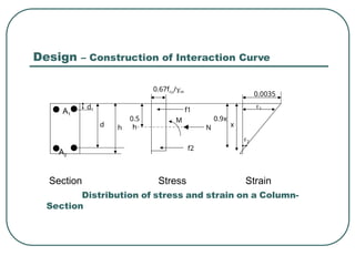
Design – Constructionof Interaction Curve
A1
A2
Section Stress Strain
Distribution of stress and strain on a Column-
Section
d1
d h
0.5
h
f1
f2
M
N x
0.9x
1
2
0.67fcu/m
0.0035
15.
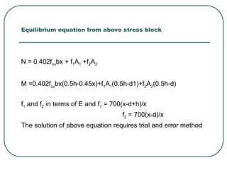
Equilibrium equation fromabove stress block
N = 0.402fcubx + f1A1 +f2A2
M =0.402fcubx(0.5h-0.45x)+f1A1(0.5h-d1)+f2A2(0.5h-d)
f1 and f2 in terms of E and f1 = 700(x-d+h)/x
f2 = 700(x-d)/x
The solution of above equation requires trial and error method