The document summarizes the design of a secant pile wall for an emergency dump pond (EDP). Key aspects include:
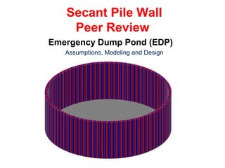
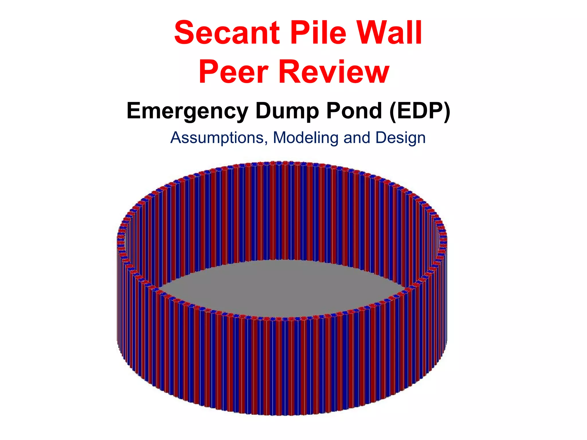
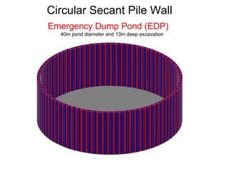
- The EDP requires a 40m diameter pond that is 13m deep for storage capacity.
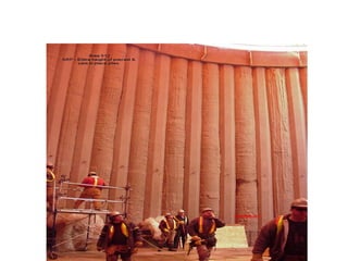
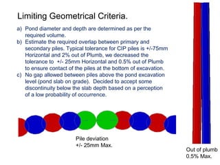
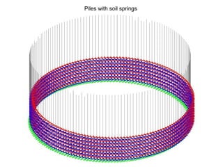
- A secant pile wall was selected to provide vertical sides for cleaning, be close to other structures, and withstand soil conditions including boulders.
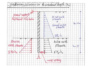
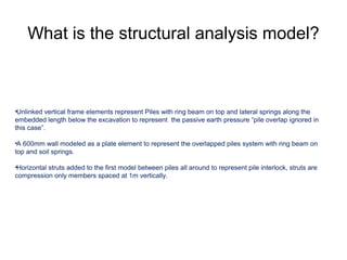
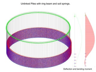
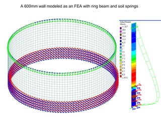
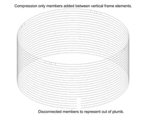
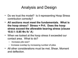
- The design considered geometric constraints, loading conditions, structural analysis models, and refined the pile size and spacing to ensure hoop stresses did not exceed allowable values.
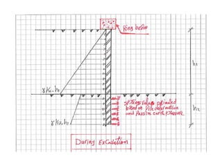
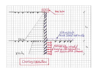
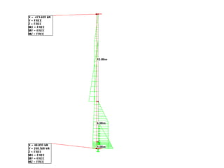
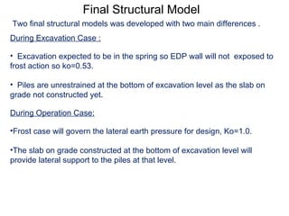
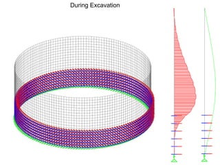
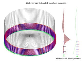
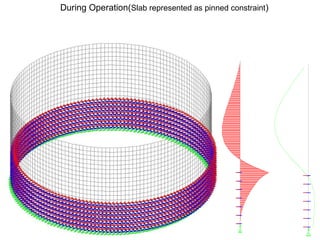
- Two design conditions were analyzed - during excavation and after the pond was in operation with a slab installed.
- Through analysis and engineering judgement, the final design met
tunnel lining may be permanent or temporary based upon their use and requirement. design of lining is done in two parts one is temporary or initial lining design and other is permanent design of the lining. empirical and theoretical methods are major design methods.
• A retaining wall construction method in which walls are constructed with small gaps between adjacent piles. The size of the space is determined by the nature of the soils.
• الخوازيق الساندة بيتم تنفيذها قبل حفر الموقع لأن وظيفتها سند جوانب الحفر
ولايتم الحفر قبل مرور 28 يوم على تنفيذ آخر خازوق ساند
• وبيتم استخدام الخوازيق البنتونيت فى حالة وجود مياة جوفية بمنسوب أعلى ممنسوب الحفرن
• وبيتم تنفيذ الخوازيق البنتونيت أولا ثم بين كل خازوقين بنتونيت يتم تنفيذ خازوق خرسانى بحيث يتداخل بالخوازيق البنتونيت أثناءالتنفي ولا تأثير انشائي له سواء الاملاء وسند التربة
The Manual explains the concept of transferring the load from the super structure up to the soil throughout Piles, which has a capacity of (End bearing, and Skin friction). It illustrates the steps needed to produce a full and safe foundation for your Super Structure.
This document will help you learn an introductory part and some detailed information on Shallow Foundations. As I am presenting this document to you I wish you all a Happy learning arena. It is highly recommended for students taking a bachelor degree in Civil Engineering, also it is a good document for students who are doing final touches for their examinations.
Class notes of Geotechnical Engineering course I used to teach at UET Lahore. Feel free to download the slide show.
Anyone looking to modify these files and use them for their own teaching purposes can contact me directly to get hold of editable version.
OUTLINE:
Introduction
Shoring Process
Effective Beam Flange Width
Shear Transfer
Strength Of Steel Anchors
Partially Composite Beams
Moment Capacity Of Composite Sections
Deflection
Design Of Composite Sections
mat/raft footing, combined footing, details of steel in construction, footing, foundation, building construction, lightning and construction, ppt on design of construction, shallow foundation, deep foundation, strap footing, pair foundation, pile foundation, well foundation, squire foundation, depth of foundation, advantage of foundation
Understanding Gridshell Structures - Mannheim Multihalle Case StudyAbhimanyu Singhal
The Mannheim Multihalle is a physical proof that little more than simple math and a detailed model could be used to create a structure with both organic materials and form.
In this you will find some of the basic thing regarding the elevated water tank and this is our one of the team project work in college. Hope you will enjoy it....
A Stress Ribbon Bridge is a tension structure (similar in many ways to a simple suspension bridge). The suspension cables are embedded in the deck which follows a catenary arc between supports.
Tube structures and its type with comparison .Udayram Patil
Hollow tube section always provide greater strength. So the same concept is applied to the building. Tubed system is designed to act like a three dimensional hollow tube structure which result in increased load resistance .
The design of Elements of Lifts and Escalator from Civil Engineering point of view. Mainly Raft foundation, Machine Foundation, and Shear walls are discussed.
Economic Design of Water Tank of Different Shapes With Reference To IS: 3370 ...IJMER
The conventional method of designing water tanks which is working stress method
outlined in the previous version of IS: 3370 1965 is irrational and leads to relatively thicker sections
with a substantial amount of reinforcement. Limit state method which is widely used has been recently
adopted in the new version of IS 3370-2009 concrete structures for storage of liquids – code of
practice. For quick cost prediction of tanks, this study therefore examines the cost effectiveness in terms
of amount of materials and formwork used for Circular, Square and Rectangular overhead water tanks
each of three capacities of 100kl, 150kl, 200kl and draw reasonable inferences on tank’s shape design
effectiveness . Each water tank was designed by Limit State method and then the crack width was
checked by limit state of serviceability IS 3370 (2009). The results have been presented in the form of
graphs and tables and it has been observed that Circular-shaped tank consumed lesser of each
material as compared to Square and Rectangular ones. The amount of formwork required for circular
tank is also less than that for square and rectangular tanks thereby giving Circular-shaped tanks a
more favorable selection over the rectangular and square shaped tanks
Similar to Secant pile wall for emergency dump pond (20)
CFD Simulation of By-pass Flow in a HRSG module by R&R Consult.pptxR&R Consult
CFD analysis is incredibly effective at solving mysteries and improving the performance of complex systems!
Here's a great example: At a large natural gas-fired power plant, where they use waste heat to generate steam and energy, they were puzzled that their boiler wasn't producing as much steam as expected.
R&R and Tetra Engineering Group Inc. were asked to solve the issue with reduced steam production.
An inspection had shown that a significant amount of hot flue gas was bypassing the boiler tubes, where the heat was supposed to be transferred.
R&R Consult conducted a CFD analysis, which revealed that 6.3% of the flue gas was bypassing the boiler tubes without transferring heat. The analysis also showed that the flue gas was instead being directed along the sides of the boiler and between the modules that were supposed to capture the heat. This was the cause of the reduced performance.
Based on our results, Tetra Engineering installed covering plates to reduce the bypass flow. This improved the boiler's performance and increased electricity production.
It is always satisfying when we can help solve complex challenges like this. Do your systems also need a check-up or optimization? Give us a call!
Work done in cooperation with James Malloy and David Moelling from Tetra Engineering.
More examples of our work https://www.r-r-consult.dk/en/cases-en/
Sachpazis:Terzaghi Bearing Capacity Estimation in simple terms with Calculati...Dr.Costas Sachpazis
Terzaghi's soil bearing capacity theory, developed by Karl Terzaghi, is a fundamental principle in geotechnical engineering used to determine the bearing capacity of shallow foundations. This theory provides a method to calculate the ultimate bearing capacity of soil, which is the maximum load per unit area that the soil can support without undergoing shear failure. The Calculation HTML Code included.
Industrial Training at Shahjalal Fertilizer Company Limited (SFCL)MdTanvirMahtab2
This presentation is about the working procedure of Shahjalal Fertilizer Company Limited (SFCL). A Govt. owned Company of Bangladesh Chemical Industries Corporation under Ministry of Industries.
Saudi Arabia stands as a titan in the global energy landscape, renowned for its abundant oil and gas resources. It's the largest exporter of petroleum and holds some of the world's most significant reserves. Let's delve into the top 10 oil and gas projects shaping Saudi Arabia's energy future in 2024.
Student information management system project report ii.pdfKamal Acharya
Our project explains about the student management. This project mainly explains the various actions related to student details. This project shows some ease in adding, editing and deleting the student details. It also provides a less time consuming process for viewing, adding, editing and deleting the marks of the students.
2. Secant pile walls are formed by drilling secondary piles
between previously installed primary piles to form a
continuous system with mechanical interlocking joints.
What are Secant Pile Walls?
3.
4. Circular Secant Pile Wall
Emergency Dump Pond (EDP)
40m pond diameter and 13m deep excavation
5. Project Requirements
• Dumping pond with vertical sides for cleanout. Earth
Ponds are difficult to clean out.
• Close to the primary separation cell (PSC).
• Construction of EDP cannot interfere with PSC erection.
• EDP Pond Required for 1.5 PSC Volume.
• Concern about soil profile (boulders) limited maximum
depth of EDP.
• Pond would be water resistant, not water tight.
6. Conceptualization
• There are two fundamental considerations that affect the
conceptualization of a secant system;
– Limiting Geometric Considerations:
– Analysis and Design Considerations:
• Some Analysis and Design Considerations are inter-related with the Geometric restraints
• Reinforce each section or reinforce alternate piles?
– Initial concept was not excessively deep and in compressive
hoop stress. Assumes arch develops to reinforced pile.
– Hoop Stress = Pressure X Radius/Thickness
7. a) Pond diameter and depth are determined as per the
required volume.
b) Estimate the required overlap between primary and
secondary piles. Typical tolerance for CIP piles is +/-75mm
Horizontal and 2% out of Plumb, we decreased the
tolerance to +/- 25mm Horizontal and 0.5% out of Plumb
to ensure contact of the piles at the bottom of excavation.
c) No gap allowed between piles above the pond excavation
level (pond slab on grade). Decided to accept some
discontinuity below the slab depth based on a perception
of a low probability of occurrence.
Out of plumb
0.5% Max.
Pile deviation
+/- 25mm Max.
Limiting Geometrical Criteria.
8. Reinforce each section or reinforce alternate piles?
Initial concept was not excessively deep and assumed in
compressive hoop stress. Assumed arch develops to transfer
loads to reinforced pile, reinforce every second pile.
Fundamentals of the Design and Analysis: Hoop Stress = Pr/t,
Moment, Shear, Bearing, Active, Passive, At Rest.
Strength yes, but do we care about Serviceability?
Analysis and Design Considerations
9. Two Design Conditions:
During Excavation to 13.5 meters depth. Ring beam installed prior
to excavation. Lateral earth pressure within excavation is Ka or
(Ko?)? Pile section below the excavation is Ka, Ko or Kp?
During operation. Slab at 12.5 meters supports and defines Ko
section. Pile section below slab resisted by Kp. (or does it??)
10.
11.
12.
13.
14. Loading and Load Combinations.
a) Piles self weight.
b) Lateral Earth Pressure
a) At Rest pressure coefficient (Ko) used from the top of piles
down to the excavated depth. Ring beam installed prior to
excavation. ( Ko=1 in case of frozen soil or Ko=0.53 unfrozen).
b) Active pressure below the excavation level was resisted by
springs simulating passive earth pressure.
c) Surcharge load of 12KPa acting uniformly for full extent of the pile.
Later refined to Terzaghi and Peck equations for consideration of an
adjacent pump house (initially assumed on piles but now on gravel
pad).
d) Wheel load as per CL-800 truck, axel load = 175KN.
e) No surcharge or wheel load was assumed to transfer lateral loads
when on top of frozen soil.
f) All loading factored for Limit States.
19. What is the structural analysis model?
•Unlinked vertical frame elements represent Piles with ring beam on top and lateral springs along the
embedded length below the excavation to represent the passive earth pressure “pile overlap ignored in
this case”.
•A 600mm wall modeled as a plate element to represent the overlapped piles system with ring beam on
top and soil springs.
•Horizontal struts added to the first model between piles all around to represent pile interlock, struts are
compression only members spaced at 1m vertically.
20. Unlinked Piles with ring beam and soil springs.
Deflection and bending moment
21. A 600mm wall modeled as an FEA with ring beam and soil springs
24. Compression only members added between vertical frame elements.
Disconnected members to represent out of plumb.
25. Final Structural Model
During Excavation Case :
• Excavation expected to be in the spring so EDP wall will not exposed to
frost action so ko=0.53.
• Piles are unrestrained at the bottom of excavation level as the slab on
grade not constructed yet.
During Operation Case:
•Frost case will govern the lateral earth pressure for design, Ko=1.0.
•The slab on grade constructed at the bottom of excavation level will
provide lateral support to the piles at that level.
Two final structural models was developed with two main differences .
29. Analysis and Design
• Do we trust the model? Is it representing Hoop Stress
contribution correctly?
• All sections must meet the fundamentals. What is
the hoop stress? Stress = Pr/t. Does the hoop
stress exceed the allowable bearing stress (clause
10.8.1- 0.85 Фc fc’ A)
• When we looked at the hoop stress it exceeded our
contact area. What to do?
– Increase pile size?
– Increase overlap by increasing number of piles
• All other considerations must be met, Shear, Moment
and deflection.
30. Final Design
• Meet the fundamentals – make sure transfer of
theoretical maximum hoop stress is possible. Bearing
governed the initial design, we increased the overlap by
adding piles to ensure the foundation of the design
philosophy, hoop stress, was maintained.
• Design is refined by establishing the extreme boundaries
to guide us toward acceptance of model results. Look at
no hoop stress and full hoop stress.
• There are no templates, the design relies heavily on
engineering judgement. Do not try this at home.
Editor's Notes
Add what a Tangent Wall is.
40 meters diameter, slab 12.5 meters from grade and 19 meter long piles. Ring beam cast at top tieing in all piles.
Initial suggestion is to dump directly into EDP by placing under PSC. Rejected because of uncertainty in construction time, critical equipment risk.
Boulders at 11 to 15 meters, suggested piles do not enter boulder zone.
During Excavation: We used Ko within the excavation, Ka below the excavation and springs simulating Kp.
Operation: We used Ko frozen to slab depth, Ka below and resisted by Kp.
Hoop stress question: When is diameter so large that wall acts linear?? Getting close at 40m diameter.
Diameter 40 meters, depth to base 10 meters plus trench allowance 2.5 meters. Initial pile length estimated at 16 meters, later revised to account for 2.5 meters of trench that enters the wall at grade. Initially the client did not allow the trench to be flooded (later revised to allow 1.0 meters of trench to be flooded..
Based on the at rest and active earth pressure Versus Passive earth pressure, 2D staad model for a single pile used to indicate the resultant of these forces at the bottom of the pile.
Explain discontinuity
Explain why the discontinuity?????
This is equivalent to the Tangent Pile system. Gives us a sensitivity to the extremes and guides us toward a refined solution.
This is the Ideal case at which piles will behave as retaining wall. This is the other extreme. We lie somewhere in between.
Next Two Slides are illustrating this slide.
Tangent wall.
The disconnected members were later deemed redundant.
We have two modeling cases first is during excavation which means no floor slab to constraint the piles at the bottom of excavation level, second is during operation which means piles are restraint at the slab level.
No floor slab to constraint the piles at the bottom of excavation level
During Operation Model, piles are restraint at slab level at max. Moment.