SlideShare a Scribd company logo
FSAN NG-PON white paper – Section 1
                              draft 0.31.0

Schedule
   - Draft 1 to be agreed in June 2008.
   - To be completed in the 1st meeting in 2009.

Editors
     Section           Editors
     Section 1, 4      Junichi Kani (NTT), and Russell Davey (BT) Fabrice Bourgart
                       (FT) and Anna Cui (AT&T)
      Section 2        Hiroaki Mukai (Mitsubishi) and Frank Effenberger (Huawei)
      Section 3        Hosung Yoon (KT) and Pat Iannone (A  T&T)


Revision history
     Version           Revision points                          Date
     0.1               The first draft                          January 14, 2008
     0.11              Input to the Vancouver meeting           January 29, 2008
                       (temporal update of draft 0.1)
      0.2              Output of the Vancouver meeting          February 15, 2008
      0.3              Output of the Tokyo meeting              June 6, 2008
      1.0              Output of the Stockholm meeting          August 13, 2008


Table of contents
1 Requirements for NG-PON
    1.1 Evolution scenario from Giga PONs
    1.2 Requirements for NG-PON1
        1.2.1 General requirements– service, capability, architecture, etc
        1.2.2 System requirements – items TBD
        1.2.3 Operational requirements
    1.3 Requirements for NG-PON2


Changes from draft 0.3
All changes from draft 0.3 are indicated with change-marks. Main changes are:


1.   The evolution-scenario illustration was updated per the agreement in Stockholm (See
     “STO_2008_FSAN_Joint_Meeting_Report_v1.ppt”).
2.   Descriptions on possible business scenarios to deploy NG-PON were added as a new

                                          1 / 17
subsection 1.1.1 based on the discussion among operators.
3.   Descriptions on system requirements were enhanced via discussion among operators.
4.   Editorial updates based on the input from Michael Rasztovits-Wiech of NSN (e-mail
     on August 7th).


Call for Contributions
Editors invite contributions to further clarify the requirements for NG-PON1 and NG-
PON2. Especially, contributions to address editors’ comments (marked in this document)
are highly encouraged.


                                        2 / 17
Abbreviations and acronyms

This document uses the following abbreviations:
ACS                Auto Configuration Server
CBU                Cellular Backhauling Unit
CDM                Code Division Multiplex
EVC                Ethernet Virtual Connection
EB                 Extender Box
FTTH               Fiber To The Home
G–PON              Gigabit-capable Passive Optical Network (ITU-T G.984 Series)
GE–PON             Gigabit Ethernet Passive Optical Network (IEEE 802.3ah)
Gigabit PON        Generic term to represent both G-PON and GE-PON
IGMP               Internet Group Multicast Protocol
ISDN               Integrated Services Digital Network
NGN                Next-Generation Networks
NG–PON             Next Generation Passive Optical Network
OAM                Operations, Administration and Maintenance
ODN                Optical Distribution Network
OFDM               Orthogonal Frequency Division Multiplexing
OLT                Optical Line Termination
OMCI               ONT Management Control Interface
ONT                Optical Network Termination
ONU                Optical Network Unit
PON                Passive Optical Network
PSTN               Public Switched Telephone Network
QoS                Quality-of-Service
RE                 Reach Extender
SLA                Service Level Agreement
SME                Small and Medium Enterprise
TC                 Transmission Convergence
TDMA               Time Division Multiple Access
TDM                Time Division Multiplexing
WBF                Wavelength Blocking Filter
WDM                Wavelength Division Multiplexing
XG–PON             10Gbit/s downstream linerate based Passive Optical Network


                                                3 / 17
Section 1 – Requirements for NG-PON


1.1         Evolution scenario from Gigabit PONs


1.1.1       Migration to NG-PON
Gigabit–class PONs such as G–PON (ITU–T G.984 series) and GE–PON (IEEE 802.3ah) were have
been standardized and are now being deployed. The most general requirement for a next–generation
PON (NG–PON) is that it must provide higher capacity than G–PON and GE–PON. Given that G–
PON and GE–PON will have been deployed by the time NG–PON is available, and given that the
major investments spent in time and money used to deploy a passive optical network optical access, a
second important requirement, is that NG–PON must assume Gigabit PON (G–PON and GE–PON) as
the base and must allow that subscribers are going to migrate gradually from Gigabit PON to NG–
PON seamlessly.


There are more than just one migration scenarios to meet different service providers’ needs. The most
likely scenario to start introducing NG-PON is the ‘service-oriented introduction scenario,’ in which
network operators start to offer a new higher capability carrier service, using NG-PON. Some
subscribers on a Gigabit PON system might be interested in such higher speed tier service and may
therefore be moved to the new service using NG-PON, while other subscribers who are happy with
their existing services may remain on the existing Gigabit PONs. Although some network operators
may do a ‘forced migration’ from Gigabit PON to NG-PON at the last stage to discontinue a PON
when the number of Gigabit PON subscribers becomes low, it is likely that both Gigabit PONs and
NG-PONs will continue to be in operation for a relatively long time in this scenario. General
requirements for this scenario are as follows:
      -     Co-existence between Gigabit PON and NG-PON in the same fiber must be supported for
            the case that the fiber resource is not necessarily abundant.
      -
      -     Service interruption for the non-upgrade subscribers should be minimized.
      -     NG PON must support/emulate all GPON legacy services in the case of full migration.


NG-PON will provide higher peak/average bandwidth per subscriber than Gigabit PON for this
scenario.


                                                   4 / 17
A quite different scenario is called ‘service-independent introduction scenario.’ In this scenario, instead
of being driven by the need of changing the provided services offered by the Giga PON, network
operators might desire to utilize NG-PON’s higher bandwidth and higher sharing ratio to extend the
provided services to a much larger number of subscribers to achieve better economics. Service
providers can either deploy NG-PON system for a new deployment or as a replacement of existing
Giga PON for re-optimization of the network.
In this case, co-existence with Gigabit PONs may not be necessary because even the replacement may
be done systematically within a relatively short time.
             The next sub-section proposes an evolution scenario of the PON technology to support the
migration.


1.2.1    Evolution scenario
             Figure 1–1–1 illustrates an example of the evolution scenario, in which NG-PON is
categorized into NG-PON1 for a mid-term upgrade and NG-PON2 for a longer-term solution. From
the viewpoint of co-existence with legacy Gigabit PONs, NG–PON1 and NG–PON2 are defined as
below:
         -      NG–PON1:        NG–PON coexisting on the same ODN as G–PON based on G.984.5
                approach,
         -      NG–PON2:        quot;Disruptivequot; NG–PON with no requirement to coexist on the same
                fibers as Gigabit PON.


                                                  5 / 17
“Co-existence” arrows mean to allow gradual
           migration in the same ODN.
                                                                                     NG-PON2
                                                                               E.g. Higher-rate TDM
                                           NG-PON1 incl.
                                                                                      DWDM
C


                                         long-reach option
p
a
y
c
t
i


                                                                                    Elect. CDM
                                                                                    OFDM,Etc.
                                        Overlay of multiple
                                     G-PON and/or XG-PON via
                                              WDM


                                              XG-PON
     G-PON   1)
                                           (Up: 2.5G to10G,
                                             Down: 10G)                       Splitter for NGA2
    GE-PON                                                                    (power splitter or
                                                                               something new)
                             Power splitter deployed for Giga PON
                                (no replacement / no addition)

    Now                             ~2010                                     ~2015


                                                                                   NG-PON2
                                                                             E.g. Higher-rate TDM
                   Component R&D to enable NG-PON2                                   DWDM
                                                                                  Elect. CDM
                                                                                   OFDM,Etc.
        “Co-existence”                    NG-PON1 incl.
        arrows mean to
C


                                        long-reach option
p
a
y
c
t
i


        allow gradual
        migration in the               WDM option to
        same ODN.                      enable to overlay
                                      multiple G/XGPONs


                                             XG-PON
     G-PON                               (Up: 2.5G to 10G,
                                           Down: 10G)                     Splitter for NG-PON2
    GE-PON                                                                 (power splitter or
                                                                            something new)

                           Power splitter deployed for Giga PON
                             (no replacement / no addition)
    Now                            ~2010                                     ~2015
    Note

    1) G–PON ONTs must comply with ITU–T G.984.5 Section 6 & 7 to allow coexistence

    2) G–PON with a reachn extender box (where used) should be able to follow this path as well with a

    possible necessity to update the reach extender box .

                              Figure 1-1-1        Evolution scenario

Figure 1–1–1 includes NG–PON1 and NG–PON2, which are defined as below;


                                                6 / 17
-    NG–PON1:       NG–PON coexisting on same ODN as G–PON based on G.984.5
              approach,
         -    NG–PON2:       quot;Disruptivequot; NG–PON with no requirement to coexist on same fibers as
              Gigabit PON.
XG–PON in the figure above represents a PON system with 10-Gbit/s line rate, at least in downstream
direction.   Upstream line rate may rangecandidates are among 2.5 andto 10 Gbit/s considering
depending on the target applications as well as cost and feasibility of the devices. XG-PON1 is 2.5
Gbp/s upstream and 10 Gbp/s downstream line rates. XG-PON2 is 10 Gbit/s symmetric line rates.


NG-PON1 includes several technology options, such as XG-PON, as well as overlay of multiple G-
PONs and/or XG-PONs into over a single feeder fiber using multiple wavelength channels, etc. ; A
distinct feature of NG-PON1 is the capability of the coexistence with G–PON on the same ODN using
the G.984.5 approach although the particular wavelength allocation plan needed to achieve this
requires further study. This coexistence feature of NG-PON1 PON overlay in this way allows a
capacity upgrade of individual customers on an operating ODN without disrupting services of other
quot;legacy PONquot; customers.


It is worth mentioning that overlay G-PONs option is a simple extension of the existing G-PON
system from protocol perspective. Twhile the only standardization and development effort required is
in the physical layer optics, i.e.: TC layer is left unchanged. For example, overlaid overlay G–PONs
could involve defining additional variants of G–PON all having the same TC layer but differing
wavelengths. It should be assumed that power splitters deployed for Gigabit PONs are used with
neitherwill not be replacedment nor addition changed in order to avoid simultaneous service outage of
the existing PON as well as to avoid the additional labor work on the ODN. In this waytechnology
option, a standard 1490/1310 nm G–PON can be deployed at from day one. When individual
customers start requesting higher bandwidth, they could beoperators can migrate themd to a different
wavelength G–PON by simply by changingreplacing the blue ONUs by the brown the ONUs, as
shown in Figure 1-1-2.: Tthe deployed ODN is reusedremains unchanged as it is. As long as operators
control theonly a few number of customers that get upgraded to a given wavelength G-PON, the
migrated subscribersthen they will receive higher capacity than the customers still connected to the
1490/1310 nm G–PON. Figure 1-1-2 shows an example of the overlay G-PON for clarification.


                                               7 / 17
ONU        ONU                                            GPON
        ONU
                                                                            OLT

                                                          15xx/15yy nm
                                                                           WDM1         GPON
                ONU
                                                                                         OLT
          ONU
                      ONU                e.g. 32-way split GPON gives each
                                         customer sustained bandwidth 80/40 Mbit/s
                            ONU

                      ONU

                                                                                     Key

                                                                         ONU


                                                                         GPON     1490nm/1310 nm GPON
 e.g. upgrade 4 customers to overlay GPONs                                OLT


 giving them 622/155 Mbit/s each
                                                                         ONU

                                                                       GPON
                                                                                  Overlay GPON
                                                                        OLT       (15xx/15yy nm )


                                  Figure 1-1-2   Example of overlay G-PON

Figure 1–1–3 shows reference –diagram examples to further clarify the scope of NG–PON1 and NG–
PON2. In Figure 1–1–3(a), NG–PON1 coexists with G–PON and an optical video distribution via
WDM1. A single stage splitter is shown as an example, but a multi-stage splitter is also applicable. A
2-by-N splitter is also applicable instead of WDM1 to combine/isolate G–PON signals and other
signals as described in ITU–T G.984.5. Note that this reference diagram is an example and other
configurations are possible: the minimum requirement is to realize the coexistence with G–PON on the
same ODN with no change. On the contrary, NG–PON2 doesn’t assume the coexistence with any
other systems as shown in Figure 1–1–3(b). Component research and developments (R&D) to
potentially make NG-PON2 beto an innovative long-
                                                term solution areis v important.
[Need to further clarify migration scenarios by operator contributions. Need to discuss possible
reduction of the number of options as well as possible migration paths among the options.]


                                                 8 / 17
ONU (G–PON)                             IFG–PON                                             IFG–PON
                                                                                                                        OLT (G–PON)
                                                     Class B+ (or over with EB)
              Tx
                                                                                                                   Rx
  Logic                        WDM-N
                                                                                                     WDM-L                  Logic
              Rx      WBF
                                                                                                                   Tx


ONU (G–PON + video)                                                                                          Legacy G-PON unchanged
              Tx
  Logic
              Rx      WBF      WDM-N'
                                                                                                   IFVideo                    Optional
           V-Rx       WBF-V                                                                                  OLT (video)
                                                     Splitter                  WDM1
                                IFG–PON , IFVideo                                        WDM2


                   IFNG–PON1                          • Multi-stage splitter available                       IFNG–PON1 OLT (NG–PON1)
ONU (NG–PON1)
                                                      • 2-by-N splitter available
                               Additional               instead of WDM1 (see Figure             Additional
                               split TBD                3 of ITU-T G.984.5)                     split TBD


                                               Class C (or C++ with optical post/pre-amplifiers)


                                                        (1) NG-PON1

ONU (NG–PON2)      IFNG–PON2                                                                                 IFNG–PON2 OLT (NG–PON2)


                                                                 TBD


                                                           Budget: TBD

                                                        (2) NG-PON2

ONU (G–PON)                             IFG–PON                                             IFG–PON
                                                                                                                        OLT (G–PON)
                                                     Class B+ (or over with EB)
              Tx               WDM                                                                                 Rx
  Logic
                                -N                                                                   WDM-L                  Logic
              Rx      WBF
                                                                                                                   Tx


ONU (G–PON + video)                                                                                          Legacy G-PON unchanged
              Tx
  Logic                        WDM
              Rx      WBF
                                -N'
                                                                                                   IFVideo                    Optional
           V-Rx       WBF-V                                                                                  OLT (video)
                                                     Splitter                  WDM1
                                IFG–PON , IFVideo                                        WDM2


                   IFNG–PON1                          • Multi-stage splitter available                       IFNG–PON1 OLT (NG–PON1)
ONU (NG–PON1)
                                                      • 2-by-N splitter available
                               Additional               instead of WDM1 (see Figure             Additional
                               split TBD                3 of ITU-T G.984.5)                     split TBD


                                               Class C (or C++ with optical post/pre-amplifiers)


                                                        (1) NG-PON1

ONU (NG–PON2)      IFNG–PON2                                                                                 IFNG–PON2 OLT (NG–PON2)


                                                                 TBD


                                                           Budget: TBD

                                                        (2) NG-PON2


                                                                9 / 17
Figure 1–1–3       Reference–diagram examples of NG–PON1 and NG–PON2

Functions of WDFs and WDMs in Fig. 1–1–2 3 are as follows.
WBF                Wavelength Blocking Filter for blocking the interference signals to Rx.
WBF-V              Wavelength Blocking Filter for blocking the interference signals to V-Rx.
WDM-N               WDM filter in G–PON ONU to combine/isolate the wavelengths of G–PON
                    upstream and downstream.
WDM-N’              WDM filter in G–PON ONU to combine/isolate the wavelengths of G–PON
                    upstream and downstream and isolate the video signal(s).
WDM-L               WDM filter in G–PON OLT to combine/isolate the wavelengths of G–PON
                    upstream and downstream.
WDM1                WDM filter which is located in the central office to combine/isolate the
                    wavelengths of G–PON and NG–PON1/video signals.
WDM2                WDM filter which may be located in the central office to combine/isolate the
                    wavelengths of NG–PON1 and video signals.


An individual operator may deploy NG–PON 1 and/or NG–PON2 depending on deployment
situations, but NG–PON equipment used in NG–PON1 and 2 should be as common as much as
possible to prevent a situation where NG–PON1 and 2 become competitive alternatives for the same
market. [Editors note: we need further clarification on what level of commonality is required between
NG–PON1 and 2 and what migration path should be possible between NG-PON1 and NGPON2.]


1.2      Requirements for NG-PON1


1.2.1    General requirements
(1) Services
Telecommunication networks are evolving from traditional circuit-based networks to the packet-based
(i.e. IP/Ethernet-oriented) next-generation networks (NGN) so that theyit can flexibly effectively
provide various services with a common platform [1, 2]. NG–PON is required to fully support current
existing revenue generating and future NGN–enabled services for residential subscribers and business
customers through its broadband capability. As for legacy services, such as PSTN and ISDN, NG-
PON basically should supports them via emulation/simulation [2]., NG–PON primarily assumes to
support the legacy services via emulation as well as long as performance of the emulation is

                                               10 / 17
acceptable. The examples of the services are summarized in Table 1–2–1. Note that two options can
be assumed for the emulation: one is is that terminationed at OLT/ONT and the other isthe other is the
end-to-end emulation over the network (e.g. NGN in backbone + NG–PON in access). Table 1–2–1
summarizes some example services of NG-PON.


          To support various services, NG-PON shall support proper QoS treatment to business
applications as well as to consumer applications. For the business applications, NG-PON should
provide access to Ethernet services such as point-to-point, multipoint-to-multipoint and rooted-
multipoint Ethernet Virtual Connection (EVC) services, so-called E-Line, E-LANan and E-Tree,
respectively.


                            Table 1–2–1        Examples of NG-PON1 services
    No.         Service                        Remark
    1           Telephony           VoIP
    2                               POTS       Emulation is assumed primarily
    3

                                                        -    E.g. Packetized Voice at ONT
                                    ISDN       Emulation is assumed primarily.
    4           TV (real time)      IP-TV      To be transported using IP multicast/unicast

                                               Note: IPTV may be transmitted by using PON
                                               broadcasting via an optical splitter
                                               [Editors note: more clarification may be needed on how
                                               to deal with IP-TV channels, e.g. where IGMP pruning
                                               is done (ONT, OLT or somewhere else).]
                                    digital    Transported using RF-video overlay (see ITU-T
                                    TV         G.983.3).
                                    broadcas
                                    ting
    5           Leased line         T1/E1      Emulation is assumed primarily.

                                               [Needs clarification on the synchronization method?]
    6           High speed                     UNI is Gigabit Ethernet typically
                Internet access
    7           timing-related      clock
                services            delivery


(2) Architecture
FTTx:                  NG–PON should primarily accommodate to FTTH architecture, i.e. a dedicated
ONT is located at each residential house, and also accommodate to FTTBuilding in case of apartment
and for exampleinstance.          NG–PON should also be capable of serving SMEs, wireless access

                                                  11 / 17
basestationsell site backhaul (i.e. ONT is used as CBU), and FTTCabinet/Curb. For supporting the
wide range of applications, optical parameters for ONUs/ONTs should be determined to allow an
outdoor operation.


Splitter location:   The position location of optical splitters in PON is an important factor in
minimizing the overall cost. If the density of customers is high, placing the splitter closer to the
customers is more effective because the shared fiber is a larger percentage of the access-line length.
On the other hand, if customer densiy is not so high, it is inefficient to place a splitter having a high
                                   t
split ratio close to one customer because it forces the others to use long cabl s to reach the splitter. A
                                                                              e
two stage splitter allocation, one near the customers and the other inthe operators building, is effective
when the customer density is medium. Furthermore, the third and the fourth stage of splitters may be
located in the higher or lower access network level as described later with Figure 1–2–1. Therefore,
NG-PON shall assume both theof single-stage and multi-stage splitter allocation.


Protection:          By the time NG–PON is deployed, operators expect a diverse range of important
services to be delivered via FTTH and thus NG–PON should allow the option of enhanced availability
figures compared to today’s FTTH solutions having no protection typically. In particular, the failures
of the shared portions of the PON will impact multiple customers, and so protection is especially
important in these cases. Note that the preparedness of the protection option shall not increase the
fixed cost of unprotected NG–PON. [Some required specifications such as a protection speed should
be discussed.]


(3) Capability
Bitrate:             In order to support continuous service enhancement including those listed in Table
1–1, the basic requirement for the NG-PON1 is to give each customer access to a maximum of one
wavelength at 10 Gbit/s downstream and a maximum of one wavelength at 2.5 to 10 Gbit/s upstream
(XG-PON option), or maximum 2.5 Gbit/s downstream and 1.25 Gbit/s upstream (overlay G-PON
option). The number of wavelengths for a given NG-PON shall be determined as notwithout
impacting the system cost. A higher number of wavelengths achieved with additional cost is for
further study. One or more of the wavelengths shall be compatible to co-existence with RF video
(basic wavelengths) while the other wavelengths may be overlapped with RF video (optional
wavelengths).


Loss budget: The basic requirement for the NG-PON1 loss budget is to realize class C without optical
post/pre-amplifiers and class C++ with optical post/pre-amplifiers. A higher loss budget is for further
study.

                                                 12 / 17
Split ratio:         As many network operators have constructed their ODN infrastructure with 32 to
64 split for Gigabit PONs, 64–way split should be the minimum requirement for NG–PON1 to allow
coexistence described in Sec. 1.1. A generic deployment of Gigabit PONs is shown in Figure 1–2–1
(a), in which a single–split model is a variation special case, where m=64 and n=1 for example:and no
splitter is needed in the access node in this case. It is attractive for network operators to extend the
split to much more than 32 (e.g. 128 to 256) because it may allow to extend PON into higher network
level as shown in Figure 1–2–1(b) and/or to extend PON into lower network level as shown in Figure
1–2–1(c). Additionally, an aggregation of multiple PON in the electrical domain as shown in Figure
1–2–1(d) is possible as an option to optimize traffic aggregation/concentration between PON and
higher-layer switching equipment: in this way, it is possible to down-size or eliminate switching
equipment in each access node, thus allowing the network operators to accommodate a huge number of
broadband subscribers in the truly optical era. Considering these options, the NG–PON TDMA control
function should be prepared to support a 256–way (or over [under discussion]) logical split while
physical split in optical layer must be carefully selected considering the maturity and cost-
effectiveness of optical devices.


Reach:               As many network operators have constructed their ODN infrastructure with 20-km
reach for Gigabit PONs, 20 km should be the minimum requirement for NG–PON as well. In the case
of extending PON into higher network level as illustrated in Figure 1–2–1 (b), the NG–PON TDMA
control function should support the reach of at least 60 km (or over [under discussion]). At the
physical layer, the minimum reach must be carefully determined considering the maturity and cost–
effectiveness of optical devices while the optional longer reach should be supported by adding an
REB without changing terminal equipment: this concept is identical to the one addressed in G.984.2
Amendment 1 (physical layer specifications based on cost/performance–optimized G–PON optics) and
G.984.6 (G–PON reach extender box).


                                                13 / 17
(a) Generic configuration
                ONT
                                                      Access node
                ONT
                                                              OLT
                 …

                                1:m                   1:n

                ONT
                                      m*n = 32 to 64

    (b) Support of extra split in higher access network level

                ONT                                   Access node               Consolidation node

                ONT
                                                                                         OLT
                 …


                                1:m                    1:n         1:p             1:q

                ONT
                                      m*n = 32 to 64

                                                            m*n*p*q >> 64

    (c) Support of extra split in lower access network level

           ONT                Building, settlement,
                              etc
             …


                                                       Access node
           ONT      1:r
              …


                                                               OLT

           ONT                  1:m                     1:n
             …


                                       m*n = 32 to 64
           ONT      1:r


                                 r*m*n >> 64
    (d) Electrical aggregation using PON TDMA
                                                                  OLT
                                                             OE Elec.
                ONT
                                                                  aggre-
                                                             OE
                ONT                                               Gation
                                                                   1:s
                                                             OE
                 …


                                1:m                    1:n

                ONT
                                      m*n = 32 to 64


                                           m*n*s >> 64

Note: the splitter device is not needed when the corresponding variable (i.e. m, n, p, q, r or sr) is 1.
                 Figure 1–2–1            Examples of NG–PON split configuration


                                                 14 / 17
1.2.2     System requirements

[Editors note: Contributions are invited to further develop the system requirements.]
(1) Control/Administration/ProvisioningPower saving
While growth of telecommunications greatly contributes to global environmental issues, power saving
of telecommunication network systems will also become more important in the full broadband era
from the viewpoints of both the reduction of operational expenditure (OPEX) of each network operator
as well as the contribution to the global green issue. Especially, one important aspect of the power
saving function in access networks is to keep providing the lifeline service(s) such as a voice service as
long as possible through the use of a backup battery when electricity service goes out. The minimum
sustainability options for a lifeline interface should be 4 to 8 hours for example. Given this, Aas for
the XG-PON, its TC layer shall provide enhanced energy efficiency compared to a simple speed
increase of G.984 G-PON TC layer.
          The minimum requirement is to allow two modes in XG-PON: one is the high-speed mode
and the other is a sleep mode. The third mode to allow a reduced service, e.g. a voice service only,
should be also considered depending on the effectiveness to keep the voice connection as long as
possible with a backup battery.
[Note: BT has announced to cut its carbon emissions by 80% over the next nine years
(http://www.bitc.org.uk/news_media/bt_emissions.html).]


(2) Authentication/identification
A comprehensive set of authentication and identification mechanisms has to be supported as options to
fit various requirements depending on each operator. The set shall include:
       Identification of a serial number and/or a password of each ONU in the auto-discovery
        process,
       Authentication of each ONU, or each UNI port if an ONU is shared among multiple users,
        based on IEEE 802.1X.
A simple but secure identification method is necessary for the recovery from the sleep mode in the
power saving function.
          ..
(3) Encryption and other functions against possible security threats
…[Should a GPON-like encryption in the TC layer be optional or mandatory considering that IEEE
defines IEEE802.1AE (so-called MacSec) provides an encryption mechanism universal in Ethernet
networks. Need to discuss the difference between a MacSec-like L2 encryption and a PON-native
encryption from the viewpoint of requirements.]


                                                15 / 17
(4) DBA format
The NG-PON OLT shall support Dynamic Bandwidth Assignment (DBA) for the efficient use of
upstream bandwidth among the connected ONUs. DBA can be categorized into the following two
methods:…
      -   Status reporting (SR) DBA which is based on the explicit buffer occupancy reports that are
          solicited by the OLT and submitted by the ONUs in response;
      -   Traffic monitoring (TM) DBA which is based on OLT’s observation of the traffic amount and
          its comparison with the corresponding bandwidth assignment.
          The NG-PON OLT shall allow these two methods as well as a combination of both. For
realizing multi-vendor interoperability, it is mandatory to standardize how to advertize the allocated
bandwidth from OLT to each ONU and how to report the buffer occupancy from each ONU to OLT.
          On the other hand, DBA algorithms, such as how the OLT applies the reported status
information, the entire specification of the Traffic Monitoring DBA method, and the details of the OLT
upstream scheduler, should be left outside the scope of the standard to allow flexibility in its
implementation.
[Note: DBA algorism implemented within NG–PON1 OLT is out of scope because it doesn’t affect
interoperability between NG–PON1 OLT and ONU.               The minimum requirement to realize the
interoperability is to standardize the format to carry DBA-related information between OLT and ONU
for allowing various types of DBA algorisms.]
(5) QoS and traffic management
[Contributions are invited not only from operators but also from vendors, especially G-PON QoS
experts. Reuse of G-PON functionalities asked for in the CTS should be the baseline: we don’t have to
cut&paste them from G-PON documents into the this white paper.                    Only the possible
changes/additions should be discussed and clarified.]...
(6) Eye safety
(7) Encryption and other functions against possible security threats
...
(8) Protection
[Speed, etc]...[Note: ‘Protection’ has been merged to Sec. 1.2.1(3).]
(9) Power saving


1.2.3      Operational requirements
(1) ONU/ONT management
It is necessary for network operators to keep ONT conditions under control to comply with their SLA

                                                16 / 17
to customers as well as to offer an access to UNI to other service providers in some cases. Therefore,
NG–PON shall support full PON real time management through ONT management and control
functions, where concepts and approach implemented for G–PON (e.g. OMCI) should be reused as
much as possible. NG–PON shall optionally support transparent remote configuration features and
mechanisms (e.g. TR069) as well. [Editors note: Required OAM functions must be discussed and
clarified. Section-2 editors have indicated a possibility to review and narrow down the domain
operated by OMCI. ]
[Editors note: Other requirements related to DSL Broadband forum are to be discussed.              E.g.
TR098Amd1 data model to establish a transparent (to the full OLTPON) channel between an UNI (at
ONT) and an ACS (remote auto-configuration server.] reached through the SNI interface
NG-PON shall enable an end to end optical fibre monitoring for all optical terminations. [Editors note:
co-operation between optical monitoring (segment by segment possibly) and end-to-end signal
monitoring is to be discussed similarly data consistency between means for management shall be
addressed.]


(2) PON supervision
[To describe high-level requirements, i.e. what should be achieved, rather than a list of parameters to
monitor.]


1.3         Requirements for NG–PON2
[Needs contributions!]


References
[1] ITU-T Recommendation Y.2001 (12/2004), General overview of NGN.
[2] ITU-T Recommendation Y.2201 (04/2007), NGN release 1 requirements.


                                               17 / 17

More Related Content

What's hot

Green Telecom & IT Workshop: Wireline access india_vetter
Green Telecom & IT Workshop: Wireline access india_vetterGreen Telecom & IT Workshop: Wireline access india_vetter
Green Telecom & IT Workshop: Wireline access india_vetter
BellLabs
 

What's hot (19)

Gponfundamentals short
Gponfundamentals shortGponfundamentals short
Gponfundamentals short
 
Overview of ITU-T SG 15 Q4 xDSL and G.(mg)fast
Overview of ITU-T SG 15 Q4 xDSL and G.(mg)fastOverview of ITU-T SG 15 Q4 xDSL and G.(mg)fast
Overview of ITU-T SG 15 Q4 xDSL and G.(mg)fast
 
Standardization of XDSL and MGfast in ITU-T SG15
Standardization of XDSL and MGfast in ITU-T SG15Standardization of XDSL and MGfast in ITU-T SG15
Standardization of XDSL and MGfast in ITU-T SG15
 
LTE physical layer
LTE physical layerLTE physical layer
LTE physical layer
 
Green Telecom & IT Workshop: Wireline access india_vetter
Green Telecom & IT Workshop: Wireline access india_vetterGreen Telecom & IT Workshop: Wireline access india_vetter
Green Telecom & IT Workshop: Wireline access india_vetter
 
5G NR Throughput Calculation
5G NR Throughput Calculation5G NR Throughput Calculation
5G NR Throughput Calculation
 
LTE Physical Layer Transmission Mode Selection Over MIMO Scattering Channels
LTE Physical Layer Transmission Mode Selection Over MIMO Scattering ChannelsLTE Physical Layer Transmission Mode Selection Over MIMO Scattering Channels
LTE Physical Layer Transmission Mode Selection Over MIMO Scattering Channels
 
Throughput calculation for LTE TDD and FDD systems
Throughput calculation for LTE TDD and FDD systemsThroughput calculation for LTE TDD and FDD systems
Throughput calculation for LTE TDD and FDD systems
 
Fdd or tdd
Fdd or tddFdd or tdd
Fdd or tdd
 
Pon itu
Pon ituPon itu
Pon itu
 
PAPR Reduction
PAPR ReductionPAPR Reduction
PAPR Reduction
 
Pon po tm_ae
Pon po tm_aePon po tm_ae
Pon po tm_ae
 
Comparative performance analysis of different modulation techniques for papr ...
Comparative performance analysis of different modulation techniques for papr ...Comparative performance analysis of different modulation techniques for papr ...
Comparative performance analysis of different modulation techniques for papr ...
 
Gq2411921196
Gq2411921196Gq2411921196
Gq2411921196
 
Lte throughput
Lte throughputLte throughput
Lte throughput
 
New solutions for wireless infrastructure applications
New solutions for wireless infrastructure applicationsNew solutions for wireless infrastructure applications
New solutions for wireless infrastructure applications
 
Tti bundling in fdd and tdd
Tti bundling in fdd and tddTti bundling in fdd and tdd
Tti bundling in fdd and tdd
 
Next-Gen Access Technologies: PON and DSL
Next-Gen Access Technologies: PON and DSLNext-Gen Access Technologies: PON and DSL
Next-Gen Access Technologies: PON and DSL
 
OFDM Final
OFDM FinalOFDM Final
OFDM Final
 

Similar to Sec1 V1d0 Aug13 2008 Draft

Request 100 g webcast presentation-june9_final
Request 100 g webcast presentation-june9_finalRequest 100 g webcast presentation-june9_final
Request 100 g webcast presentation-june9_final
dodesimo
 
10 gpon information technology interfaces, 2007. iti 2007. 29th internationa...
10 gpon  information technology interfaces, 2007. iti 2007. 29th internationa...10 gpon  information technology interfaces, 2007. iti 2007. 29th internationa...
10 gpon information technology interfaces, 2007. iti 2007. 29th internationa...
ngoctrampnt
 
GPON technology equipment fiberhoe technologies indo
GPON technology equipment fiberhoe technologies indoGPON technology equipment fiberhoe technologies indo
GPON technology equipment fiberhoe technologies indo
rizkiutomo1992
 
Passive Optical Networks
Passive Optical NetworksPassive Optical Networks
Passive Optical Networks
fanttazio
 

Similar to Sec1 V1d0 Aug13 2008 Draft (20)

PLNOG 8: Przemysław Dziel - NG - PON - Lights The Future Way for Broadband
PLNOG 8: Przemysław Dziel - NG - PON - Lights The Future Way for Broadband PLNOG 8: Przemysław Dziel - NG - PON - Lights The Future Way for Broadband
PLNOG 8: Przemysław Dziel - NG - PON - Lights The Future Way for Broadband
 
Request 100 g webcast presentation-june9_final
Request 100 g webcast presentation-june9_finalRequest 100 g webcast presentation-june9_final
Request 100 g webcast presentation-june9_final
 
07114069
0711406907114069
07114069
 
10 gpon information technology interfaces, 2007. iti 2007. 29th internationa...
10 gpon  information technology interfaces, 2007. iti 2007. 29th internationa...10 gpon  information technology interfaces, 2007. iti 2007. 29th internationa...
10 gpon information technology interfaces, 2007. iti 2007. 29th internationa...
 
Gpon Fundamentals
Gpon FundamentalsGpon Fundamentals
Gpon Fundamentals
 
Gpon Fundamentals
Gpon FundamentalsGpon Fundamentals
Gpon Fundamentals
 
Gsc20 session6 5_g_chih_ieee
Gsc20 session6 5_g_chih_ieeeGsc20 session6 5_g_chih_ieee
Gsc20 session6 5_g_chih_ieee
 
Combo PON Has Become the Principal Solution for 10G GPON Construction
Combo PON Has Become the Principal Solution for 10G GPON ConstructionCombo PON Has Become the Principal Solution for 10G GPON Construction
Combo PON Has Become the Principal Solution for 10G GPON Construction
 
GPON technology equipment fiberhoe technologies indo
GPON technology equipment fiberhoe technologies indoGPON technology equipment fiberhoe technologies indo
GPON technology equipment fiberhoe technologies indo
 
Gpon the technology --rev 1
Gpon the technology --rev 1Gpon the technology --rev 1
Gpon the technology --rev 1
 
Gpon the technology --rev 1
Gpon the technology --rev 1Gpon the technology --rev 1
Gpon the technology --rev 1
 
Convergence Access Networks Challenge Gpon
Convergence Access Networks Challenge GponConvergence Access Networks Challenge Gpon
Convergence Access Networks Challenge Gpon
 
C.pdf
C.pdfC.pdf
C.pdf
 
Active Technologies, The Sky is the limit
Active Technologies, The Sky is the limitActive Technologies, The Sky is the limit
Active Technologies, The Sky is the limit
 
Gpon fundamentals
Gpon fundamentalsGpon fundamentals
Gpon fundamentals
 
Gpon fundamentals
Gpon fundamentals Gpon fundamentals
Gpon fundamentals
 
Huawei GPON Fundamentals
Huawei GPON FundamentalsHuawei GPON Fundamentals
Huawei GPON Fundamentals
 
Huawei OLT Ma5600 & 5608t GPON feature glance
Huawei OLT Ma5600 & 5608t GPON feature glanceHuawei OLT Ma5600 & 5608t GPON feature glance
Huawei OLT Ma5600 & 5608t GPON feature glance
 
Passive Optical Networks
Passive Optical NetworksPassive Optical Networks
Passive Optical Networks
 
GPON-Doctor 8000
GPON-Doctor 8000GPON-Doctor 8000
GPON-Doctor 8000
 

Recently uploaded

Essentials of Automations: Optimizing FME Workflows with Parameters
Essentials of Automations: Optimizing FME Workflows with ParametersEssentials of Automations: Optimizing FME Workflows with Parameters
Essentials of Automations: Optimizing FME Workflows with Parameters
Safe Software
 

Recently uploaded (20)

UiPath Test Automation using UiPath Test Suite series, part 2
UiPath Test Automation using UiPath Test Suite series, part 2UiPath Test Automation using UiPath Test Suite series, part 2
UiPath Test Automation using UiPath Test Suite series, part 2
 
When stars align: studies in data quality, knowledge graphs, and machine lear...
When stars align: studies in data quality, knowledge graphs, and machine lear...When stars align: studies in data quality, knowledge graphs, and machine lear...
When stars align: studies in data quality, knowledge graphs, and machine lear...
 
НАДІЯ ФЕДЮШКО БАЦ «Професійне зростання QA спеціаліста»
НАДІЯ ФЕДЮШКО БАЦ  «Професійне зростання QA спеціаліста»НАДІЯ ФЕДЮШКО БАЦ  «Професійне зростання QA спеціаліста»
НАДІЯ ФЕДЮШКО БАЦ «Професійне зростання QA спеціаліста»
 
In-Depth Performance Testing Guide for IT Professionals
In-Depth Performance Testing Guide for IT ProfessionalsIn-Depth Performance Testing Guide for IT Professionals
In-Depth Performance Testing Guide for IT Professionals
 
FIDO Alliance Osaka Seminar: FIDO Security Aspects.pdf
FIDO Alliance Osaka Seminar: FIDO Security Aspects.pdfFIDO Alliance Osaka Seminar: FIDO Security Aspects.pdf
FIDO Alliance Osaka Seminar: FIDO Security Aspects.pdf
 
Quantum Computing: Current Landscape and the Future Role of APIs
Quantum Computing: Current Landscape and the Future Role of APIsQuantum Computing: Current Landscape and the Future Role of APIs
Quantum Computing: Current Landscape and the Future Role of APIs
 
The Future of Platform Engineering
The Future of Platform EngineeringThe Future of Platform Engineering
The Future of Platform Engineering
 
From Siloed Products to Connected Ecosystem: Building a Sustainable and Scala...
From Siloed Products to Connected Ecosystem: Building a Sustainable and Scala...From Siloed Products to Connected Ecosystem: Building a Sustainable and Scala...
From Siloed Products to Connected Ecosystem: Building a Sustainable and Scala...
 
Dev Dives: Train smarter, not harder – active learning and UiPath LLMs for do...
Dev Dives: Train smarter, not harder – active learning and UiPath LLMs for do...Dev Dives: Train smarter, not harder – active learning and UiPath LLMs for do...
Dev Dives: Train smarter, not harder – active learning and UiPath LLMs for do...
 
Exploring UiPath Orchestrator API: updates and limits in 2024 🚀
Exploring UiPath Orchestrator API: updates and limits in 2024 🚀Exploring UiPath Orchestrator API: updates and limits in 2024 🚀
Exploring UiPath Orchestrator API: updates and limits in 2024 🚀
 
Essentials of Automations: Optimizing FME Workflows with Parameters
Essentials of Automations: Optimizing FME Workflows with ParametersEssentials of Automations: Optimizing FME Workflows with Parameters
Essentials of Automations: Optimizing FME Workflows with Parameters
 
Designing Great Products: The Power of Design and Leadership by Chief Designe...
Designing Great Products: The Power of Design and Leadership by Chief Designe...Designing Great Products: The Power of Design and Leadership by Chief Designe...
Designing Great Products: The Power of Design and Leadership by Chief Designe...
 
ODC, Data Fabric and Architecture User Group
ODC, Data Fabric and Architecture User GroupODC, Data Fabric and Architecture User Group
ODC, Data Fabric and Architecture User Group
 
Neuro-symbolic is not enough, we need neuro-*semantic*
Neuro-symbolic is not enough, we need neuro-*semantic*Neuro-symbolic is not enough, we need neuro-*semantic*
Neuro-symbolic is not enough, we need neuro-*semantic*
 
Empowering NextGen Mobility via Large Action Model Infrastructure (LAMI): pav...
Empowering NextGen Mobility via Large Action Model Infrastructure (LAMI): pav...Empowering NextGen Mobility via Large Action Model Infrastructure (LAMI): pav...
Empowering NextGen Mobility via Large Action Model Infrastructure (LAMI): pav...
 
FIDO Alliance Osaka Seminar: Passkeys at Amazon.pdf
FIDO Alliance Osaka Seminar: Passkeys at Amazon.pdfFIDO Alliance Osaka Seminar: Passkeys at Amazon.pdf
FIDO Alliance Osaka Seminar: Passkeys at Amazon.pdf
 
Key Trends Shaping the Future of Infrastructure.pdf
Key Trends Shaping the Future of Infrastructure.pdfKey Trends Shaping the Future of Infrastructure.pdf
Key Trends Shaping the Future of Infrastructure.pdf
 
IOS-PENTESTING-BEGINNERS-PRACTICAL-GUIDE-.pptx
IOS-PENTESTING-BEGINNERS-PRACTICAL-GUIDE-.pptxIOS-PENTESTING-BEGINNERS-PRACTICAL-GUIDE-.pptx
IOS-PENTESTING-BEGINNERS-PRACTICAL-GUIDE-.pptx
 
"Impact of front-end architecture on development cost", Viktor Turskyi
"Impact of front-end architecture on development cost", Viktor Turskyi"Impact of front-end architecture on development cost", Viktor Turskyi
"Impact of front-end architecture on development cost", Viktor Turskyi
 
Speed Wins: From Kafka to APIs in Minutes
Speed Wins: From Kafka to APIs in MinutesSpeed Wins: From Kafka to APIs in Minutes
Speed Wins: From Kafka to APIs in Minutes
 

Sec1 V1d0 Aug13 2008 Draft

  • 1. FSAN NG-PON white paper – Section 1 draft 0.31.0 Schedule - Draft 1 to be agreed in June 2008. - To be completed in the 1st meeting in 2009. Editors Section Editors Section 1, 4 Junichi Kani (NTT), and Russell Davey (BT) Fabrice Bourgart (FT) and Anna Cui (AT&T) Section 2 Hiroaki Mukai (Mitsubishi) and Frank Effenberger (Huawei) Section 3 Hosung Yoon (KT) and Pat Iannone (A T&T) Revision history Version Revision points Date 0.1 The first draft January 14, 2008 0.11 Input to the Vancouver meeting January 29, 2008 (temporal update of draft 0.1) 0.2 Output of the Vancouver meeting February 15, 2008 0.3 Output of the Tokyo meeting June 6, 2008 1.0 Output of the Stockholm meeting August 13, 2008 Table of contents 1 Requirements for NG-PON 1.1 Evolution scenario from Giga PONs 1.2 Requirements for NG-PON1 1.2.1 General requirements– service, capability, architecture, etc 1.2.2 System requirements – items TBD 1.2.3 Operational requirements 1.3 Requirements for NG-PON2 Changes from draft 0.3 All changes from draft 0.3 are indicated with change-marks. Main changes are: 1. The evolution-scenario illustration was updated per the agreement in Stockholm (See “STO_2008_FSAN_Joint_Meeting_Report_v1.ppt”). 2. Descriptions on possible business scenarios to deploy NG-PON were added as a new 1 / 17
  • 2. subsection 1.1.1 based on the discussion among operators. 3. Descriptions on system requirements were enhanced via discussion among operators. 4. Editorial updates based on the input from Michael Rasztovits-Wiech of NSN (e-mail on August 7th). Call for Contributions Editors invite contributions to further clarify the requirements for NG-PON1 and NG- PON2. Especially, contributions to address editors’ comments (marked in this document) are highly encouraged. 2 / 17
  • 3. Abbreviations and acronyms This document uses the following abbreviations: ACS Auto Configuration Server CBU Cellular Backhauling Unit CDM Code Division Multiplex EVC Ethernet Virtual Connection EB Extender Box FTTH Fiber To The Home G–PON Gigabit-capable Passive Optical Network (ITU-T G.984 Series) GE–PON Gigabit Ethernet Passive Optical Network (IEEE 802.3ah) Gigabit PON Generic term to represent both G-PON and GE-PON IGMP Internet Group Multicast Protocol ISDN Integrated Services Digital Network NGN Next-Generation Networks NG–PON Next Generation Passive Optical Network OAM Operations, Administration and Maintenance ODN Optical Distribution Network OFDM Orthogonal Frequency Division Multiplexing OLT Optical Line Termination OMCI ONT Management Control Interface ONT Optical Network Termination ONU Optical Network Unit PON Passive Optical Network PSTN Public Switched Telephone Network QoS Quality-of-Service RE Reach Extender SLA Service Level Agreement SME Small and Medium Enterprise TC Transmission Convergence TDMA Time Division Multiple Access TDM Time Division Multiplexing WBF Wavelength Blocking Filter WDM Wavelength Division Multiplexing XG–PON 10Gbit/s downstream linerate based Passive Optical Network 3 / 17
  • 4. Section 1 – Requirements for NG-PON 1.1 Evolution scenario from Gigabit PONs 1.1.1 Migration to NG-PON Gigabit–class PONs such as G–PON (ITU–T G.984 series) and GE–PON (IEEE 802.3ah) were have been standardized and are now being deployed. The most general requirement for a next–generation PON (NG–PON) is that it must provide higher capacity than G–PON and GE–PON. Given that G– PON and GE–PON will have been deployed by the time NG–PON is available, and given that the major investments spent in time and money used to deploy a passive optical network optical access, a second important requirement, is that NG–PON must assume Gigabit PON (G–PON and GE–PON) as the base and must allow that subscribers are going to migrate gradually from Gigabit PON to NG– PON seamlessly. There are more than just one migration scenarios to meet different service providers’ needs. The most likely scenario to start introducing NG-PON is the ‘service-oriented introduction scenario,’ in which network operators start to offer a new higher capability carrier service, using NG-PON. Some subscribers on a Gigabit PON system might be interested in such higher speed tier service and may therefore be moved to the new service using NG-PON, while other subscribers who are happy with their existing services may remain on the existing Gigabit PONs. Although some network operators may do a ‘forced migration’ from Gigabit PON to NG-PON at the last stage to discontinue a PON when the number of Gigabit PON subscribers becomes low, it is likely that both Gigabit PONs and NG-PONs will continue to be in operation for a relatively long time in this scenario. General requirements for this scenario are as follows: - Co-existence between Gigabit PON and NG-PON in the same fiber must be supported for the case that the fiber resource is not necessarily abundant. - - Service interruption for the non-upgrade subscribers should be minimized. - NG PON must support/emulate all GPON legacy services in the case of full migration. NG-PON will provide higher peak/average bandwidth per subscriber than Gigabit PON for this scenario. 4 / 17
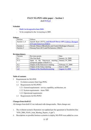
  • 5. A quite different scenario is called ‘service-independent introduction scenario.’ In this scenario, instead of being driven by the need of changing the provided services offered by the Giga PON, network operators might desire to utilize NG-PON’s higher bandwidth and higher sharing ratio to extend the provided services to a much larger number of subscribers to achieve better economics. Service providers can either deploy NG-PON system for a new deployment or as a replacement of existing Giga PON for re-optimization of the network. In this case, co-existence with Gigabit PONs may not be necessary because even the replacement may be done systematically within a relatively short time. The next sub-section proposes an evolution scenario of the PON technology to support the migration. 1.2.1 Evolution scenario Figure 1–1–1 illustrates an example of the evolution scenario, in which NG-PON is categorized into NG-PON1 for a mid-term upgrade and NG-PON2 for a longer-term solution. From the viewpoint of co-existence with legacy Gigabit PONs, NG–PON1 and NG–PON2 are defined as below: - NG–PON1: NG–PON coexisting on the same ODN as G–PON based on G.984.5 approach, - NG–PON2: quot;Disruptivequot; NG–PON with no requirement to coexist on the same fibers as Gigabit PON. 5 / 17
  • 6. “Co-existence” arrows mean to allow gradual migration in the same ODN. NG-PON2 E.g. Higher-rate TDM NG-PON1 incl. DWDM C long-reach option p a y c t i Elect. CDM OFDM,Etc. Overlay of multiple G-PON and/or XG-PON via WDM XG-PON G-PON 1) (Up: 2.5G to10G, Down: 10G) Splitter for NGA2 GE-PON (power splitter or something new) Power splitter deployed for Giga PON (no replacement / no addition) Now ~2010 ~2015 NG-PON2 E.g. Higher-rate TDM Component R&D to enable NG-PON2 DWDM Elect. CDM OFDM,Etc. “Co-existence” NG-PON1 incl. arrows mean to C long-reach option p a y c t i allow gradual migration in the WDM option to same ODN. enable to overlay multiple G/XGPONs XG-PON G-PON (Up: 2.5G to 10G, Down: 10G) Splitter for NG-PON2 GE-PON (power splitter or something new) Power splitter deployed for Giga PON (no replacement / no addition) Now ~2010 ~2015 Note 1) G–PON ONTs must comply with ITU–T G.984.5 Section 6 & 7 to allow coexistence 2) G–PON with a reachn extender box (where used) should be able to follow this path as well with a possible necessity to update the reach extender box . Figure 1-1-1 Evolution scenario Figure 1–1–1 includes NG–PON1 and NG–PON2, which are defined as below; 6 / 17
  • 7. - NG–PON1: NG–PON coexisting on same ODN as G–PON based on G.984.5 approach, - NG–PON2: quot;Disruptivequot; NG–PON with no requirement to coexist on same fibers as Gigabit PON. XG–PON in the figure above represents a PON system with 10-Gbit/s line rate, at least in downstream direction. Upstream line rate may rangecandidates are among 2.5 andto 10 Gbit/s considering depending on the target applications as well as cost and feasibility of the devices. XG-PON1 is 2.5 Gbp/s upstream and 10 Gbp/s downstream line rates. XG-PON2 is 10 Gbit/s symmetric line rates. NG-PON1 includes several technology options, such as XG-PON, as well as overlay of multiple G- PONs and/or XG-PONs into over a single feeder fiber using multiple wavelength channels, etc. ; A distinct feature of NG-PON1 is the capability of the coexistence with G–PON on the same ODN using the G.984.5 approach although the particular wavelength allocation plan needed to achieve this requires further study. This coexistence feature of NG-PON1 PON overlay in this way allows a capacity upgrade of individual customers on an operating ODN without disrupting services of other quot;legacy PONquot; customers. It is worth mentioning that overlay G-PONs option is a simple extension of the existing G-PON system from protocol perspective. Twhile the only standardization and development effort required is in the physical layer optics, i.e.: TC layer is left unchanged. For example, overlaid overlay G–PONs could involve defining additional variants of G–PON all having the same TC layer but differing wavelengths. It should be assumed that power splitters deployed for Gigabit PONs are used with neitherwill not be replacedment nor addition changed in order to avoid simultaneous service outage of the existing PON as well as to avoid the additional labor work on the ODN. In this waytechnology option, a standard 1490/1310 nm G–PON can be deployed at from day one. When individual customers start requesting higher bandwidth, they could beoperators can migrate themd to a different wavelength G–PON by simply by changingreplacing the blue ONUs by the brown the ONUs, as shown in Figure 1-1-2.: Tthe deployed ODN is reusedremains unchanged as it is. As long as operators control theonly a few number of customers that get upgraded to a given wavelength G-PON, the migrated subscribersthen they will receive higher capacity than the customers still connected to the 1490/1310 nm G–PON. Figure 1-1-2 shows an example of the overlay G-PON for clarification. 7 / 17
  • 8. ONU ONU GPON ONU OLT 15xx/15yy nm WDM1 GPON ONU OLT ONU ONU e.g. 32-way split GPON gives each customer sustained bandwidth 80/40 Mbit/s ONU ONU Key ONU GPON 1490nm/1310 nm GPON e.g. upgrade 4 customers to overlay GPONs OLT giving them 622/155 Mbit/s each ONU GPON Overlay GPON OLT (15xx/15yy nm ) Figure 1-1-2 Example of overlay G-PON Figure 1–1–3 shows reference –diagram examples to further clarify the scope of NG–PON1 and NG– PON2. In Figure 1–1–3(a), NG–PON1 coexists with G–PON and an optical video distribution via WDM1. A single stage splitter is shown as an example, but a multi-stage splitter is also applicable. A 2-by-N splitter is also applicable instead of WDM1 to combine/isolate G–PON signals and other signals as described in ITU–T G.984.5. Note that this reference diagram is an example and other configurations are possible: the minimum requirement is to realize the coexistence with G–PON on the same ODN with no change. On the contrary, NG–PON2 doesn’t assume the coexistence with any other systems as shown in Figure 1–1–3(b). Component research and developments (R&D) to potentially make NG-PON2 beto an innovative long- term solution areis v important. [Need to further clarify migration scenarios by operator contributions. Need to discuss possible reduction of the number of options as well as possible migration paths among the options.] 8 / 17
  • 9. ONU (G–PON) IFG–PON IFG–PON OLT (G–PON) Class B+ (or over with EB) Tx Rx Logic WDM-N WDM-L Logic Rx WBF Tx ONU (G–PON + video) Legacy G-PON unchanged Tx Logic Rx WBF WDM-N' IFVideo Optional V-Rx WBF-V OLT (video) Splitter WDM1 IFG–PON , IFVideo WDM2 IFNG–PON1 • Multi-stage splitter available IFNG–PON1 OLT (NG–PON1) ONU (NG–PON1) • 2-by-N splitter available Additional instead of WDM1 (see Figure Additional split TBD 3 of ITU-T G.984.5) split TBD Class C (or C++ with optical post/pre-amplifiers) (1) NG-PON1 ONU (NG–PON2) IFNG–PON2 IFNG–PON2 OLT (NG–PON2) TBD Budget: TBD (2) NG-PON2 ONU (G–PON) IFG–PON IFG–PON OLT (G–PON) Class B+ (or over with EB) Tx WDM Rx Logic -N WDM-L Logic Rx WBF Tx ONU (G–PON + video) Legacy G-PON unchanged Tx Logic WDM Rx WBF -N' IFVideo Optional V-Rx WBF-V OLT (video) Splitter WDM1 IFG–PON , IFVideo WDM2 IFNG–PON1 • Multi-stage splitter available IFNG–PON1 OLT (NG–PON1) ONU (NG–PON1) • 2-by-N splitter available Additional instead of WDM1 (see Figure Additional split TBD 3 of ITU-T G.984.5) split TBD Class C (or C++ with optical post/pre-amplifiers) (1) NG-PON1 ONU (NG–PON2) IFNG–PON2 IFNG–PON2 OLT (NG–PON2) TBD Budget: TBD (2) NG-PON2 9 / 17
  • 10. Figure 1–1–3 Reference–diagram examples of NG–PON1 and NG–PON2 Functions of WDFs and WDMs in Fig. 1–1–2 3 are as follows. WBF Wavelength Blocking Filter for blocking the interference signals to Rx. WBF-V Wavelength Blocking Filter for blocking the interference signals to V-Rx. WDM-N WDM filter in G–PON ONU to combine/isolate the wavelengths of G–PON upstream and downstream. WDM-N’ WDM filter in G–PON ONU to combine/isolate the wavelengths of G–PON upstream and downstream and isolate the video signal(s). WDM-L WDM filter in G–PON OLT to combine/isolate the wavelengths of G–PON upstream and downstream. WDM1 WDM filter which is located in the central office to combine/isolate the wavelengths of G–PON and NG–PON1/video signals. WDM2 WDM filter which may be located in the central office to combine/isolate the wavelengths of NG–PON1 and video signals. An individual operator may deploy NG–PON 1 and/or NG–PON2 depending on deployment situations, but NG–PON equipment used in NG–PON1 and 2 should be as common as much as possible to prevent a situation where NG–PON1 and 2 become competitive alternatives for the same market. [Editors note: we need further clarification on what level of commonality is required between NG–PON1 and 2 and what migration path should be possible between NG-PON1 and NGPON2.] 1.2 Requirements for NG-PON1 1.2.1 General requirements (1) Services Telecommunication networks are evolving from traditional circuit-based networks to the packet-based (i.e. IP/Ethernet-oriented) next-generation networks (NGN) so that theyit can flexibly effectively provide various services with a common platform [1, 2]. NG–PON is required to fully support current existing revenue generating and future NGN–enabled services for residential subscribers and business customers through its broadband capability. As for legacy services, such as PSTN and ISDN, NG- PON basically should supports them via emulation/simulation [2]., NG–PON primarily assumes to support the legacy services via emulation as well as long as performance of the emulation is 10 / 17
  • 11. acceptable. The examples of the services are summarized in Table 1–2–1. Note that two options can be assumed for the emulation: one is is that terminationed at OLT/ONT and the other isthe other is the end-to-end emulation over the network (e.g. NGN in backbone + NG–PON in access). Table 1–2–1 summarizes some example services of NG-PON. To support various services, NG-PON shall support proper QoS treatment to business applications as well as to consumer applications. For the business applications, NG-PON should provide access to Ethernet services such as point-to-point, multipoint-to-multipoint and rooted- multipoint Ethernet Virtual Connection (EVC) services, so-called E-Line, E-LANan and E-Tree, respectively. Table 1–2–1 Examples of NG-PON1 services No. Service Remark 1 Telephony VoIP 2 POTS Emulation is assumed primarily 3 - E.g. Packetized Voice at ONT ISDN Emulation is assumed primarily. 4 TV (real time) IP-TV To be transported using IP multicast/unicast Note: IPTV may be transmitted by using PON broadcasting via an optical splitter [Editors note: more clarification may be needed on how to deal with IP-TV channels, e.g. where IGMP pruning is done (ONT, OLT or somewhere else).] digital Transported using RF-video overlay (see ITU-T TV G.983.3). broadcas ting 5 Leased line T1/E1 Emulation is assumed primarily. [Needs clarification on the synchronization method?] 6 High speed UNI is Gigabit Ethernet typically Internet access 7 timing-related clock services delivery (2) Architecture FTTx: NG–PON should primarily accommodate to FTTH architecture, i.e. a dedicated ONT is located at each residential house, and also accommodate to FTTBuilding in case of apartment and for exampleinstance. NG–PON should also be capable of serving SMEs, wireless access 11 / 17
  • 12. basestationsell site backhaul (i.e. ONT is used as CBU), and FTTCabinet/Curb. For supporting the wide range of applications, optical parameters for ONUs/ONTs should be determined to allow an outdoor operation. Splitter location: The position location of optical splitters in PON is an important factor in minimizing the overall cost. If the density of customers is high, placing the splitter closer to the customers is more effective because the shared fiber is a larger percentage of the access-line length. On the other hand, if customer densiy is not so high, it is inefficient to place a splitter having a high t split ratio close to one customer because it forces the others to use long cabl s to reach the splitter. A e two stage splitter allocation, one near the customers and the other inthe operators building, is effective when the customer density is medium. Furthermore, the third and the fourth stage of splitters may be located in the higher or lower access network level as described later with Figure 1–2–1. Therefore, NG-PON shall assume both theof single-stage and multi-stage splitter allocation. Protection: By the time NG–PON is deployed, operators expect a diverse range of important services to be delivered via FTTH and thus NG–PON should allow the option of enhanced availability figures compared to today’s FTTH solutions having no protection typically. In particular, the failures of the shared portions of the PON will impact multiple customers, and so protection is especially important in these cases. Note that the preparedness of the protection option shall not increase the fixed cost of unprotected NG–PON. [Some required specifications such as a protection speed should be discussed.] (3) Capability Bitrate: In order to support continuous service enhancement including those listed in Table 1–1, the basic requirement for the NG-PON1 is to give each customer access to a maximum of one wavelength at 10 Gbit/s downstream and a maximum of one wavelength at 2.5 to 10 Gbit/s upstream (XG-PON option), or maximum 2.5 Gbit/s downstream and 1.25 Gbit/s upstream (overlay G-PON option). The number of wavelengths for a given NG-PON shall be determined as notwithout impacting the system cost. A higher number of wavelengths achieved with additional cost is for further study. One or more of the wavelengths shall be compatible to co-existence with RF video (basic wavelengths) while the other wavelengths may be overlapped with RF video (optional wavelengths). Loss budget: The basic requirement for the NG-PON1 loss budget is to realize class C without optical post/pre-amplifiers and class C++ with optical post/pre-amplifiers. A higher loss budget is for further study. 12 / 17
  • 13. Split ratio: As many network operators have constructed their ODN infrastructure with 32 to 64 split for Gigabit PONs, 64–way split should be the minimum requirement for NG–PON1 to allow coexistence described in Sec. 1.1. A generic deployment of Gigabit PONs is shown in Figure 1–2–1 (a), in which a single–split model is a variation special case, where m=64 and n=1 for example:and no splitter is needed in the access node in this case. It is attractive for network operators to extend the split to much more than 32 (e.g. 128 to 256) because it may allow to extend PON into higher network level as shown in Figure 1–2–1(b) and/or to extend PON into lower network level as shown in Figure 1–2–1(c). Additionally, an aggregation of multiple PON in the electrical domain as shown in Figure 1–2–1(d) is possible as an option to optimize traffic aggregation/concentration between PON and higher-layer switching equipment: in this way, it is possible to down-size or eliminate switching equipment in each access node, thus allowing the network operators to accommodate a huge number of broadband subscribers in the truly optical era. Considering these options, the NG–PON TDMA control function should be prepared to support a 256–way (or over [under discussion]) logical split while physical split in optical layer must be carefully selected considering the maturity and cost- effectiveness of optical devices. Reach: As many network operators have constructed their ODN infrastructure with 20-km reach for Gigabit PONs, 20 km should be the minimum requirement for NG–PON as well. In the case of extending PON into higher network level as illustrated in Figure 1–2–1 (b), the NG–PON TDMA control function should support the reach of at least 60 km (or over [under discussion]). At the physical layer, the minimum reach must be carefully determined considering the maturity and cost– effectiveness of optical devices while the optional longer reach should be supported by adding an REB without changing terminal equipment: this concept is identical to the one addressed in G.984.2 Amendment 1 (physical layer specifications based on cost/performance–optimized G–PON optics) and G.984.6 (G–PON reach extender box). 13 / 17
  • 14. (a) Generic configuration ONT Access node ONT OLT … 1:m 1:n ONT m*n = 32 to 64 (b) Support of extra split in higher access network level ONT Access node Consolidation node ONT OLT … 1:m 1:n 1:p 1:q ONT m*n = 32 to 64 m*n*p*q >> 64 (c) Support of extra split in lower access network level ONT Building, settlement, etc … Access node ONT 1:r … OLT ONT 1:m 1:n … m*n = 32 to 64 ONT 1:r r*m*n >> 64 (d) Electrical aggregation using PON TDMA OLT OE Elec. ONT aggre- OE ONT Gation 1:s OE … 1:m 1:n ONT m*n = 32 to 64 m*n*s >> 64 Note: the splitter device is not needed when the corresponding variable (i.e. m, n, p, q, r or sr) is 1. Figure 1–2–1 Examples of NG–PON split configuration 14 / 17
  • 15. 1.2.2 System requirements [Editors note: Contributions are invited to further develop the system requirements.] (1) Control/Administration/ProvisioningPower saving While growth of telecommunications greatly contributes to global environmental issues, power saving of telecommunication network systems will also become more important in the full broadband era from the viewpoints of both the reduction of operational expenditure (OPEX) of each network operator as well as the contribution to the global green issue. Especially, one important aspect of the power saving function in access networks is to keep providing the lifeline service(s) such as a voice service as long as possible through the use of a backup battery when electricity service goes out. The minimum sustainability options for a lifeline interface should be 4 to 8 hours for example. Given this, Aas for the XG-PON, its TC layer shall provide enhanced energy efficiency compared to a simple speed increase of G.984 G-PON TC layer. The minimum requirement is to allow two modes in XG-PON: one is the high-speed mode and the other is a sleep mode. The third mode to allow a reduced service, e.g. a voice service only, should be also considered depending on the effectiveness to keep the voice connection as long as possible with a backup battery. [Note: BT has announced to cut its carbon emissions by 80% over the next nine years (http://www.bitc.org.uk/news_media/bt_emissions.html).] (2) Authentication/identification A comprehensive set of authentication and identification mechanisms has to be supported as options to fit various requirements depending on each operator. The set shall include:  Identification of a serial number and/or a password of each ONU in the auto-discovery process,  Authentication of each ONU, or each UNI port if an ONU is shared among multiple users, based on IEEE 802.1X. A simple but secure identification method is necessary for the recovery from the sleep mode in the power saving function. .. (3) Encryption and other functions against possible security threats …[Should a GPON-like encryption in the TC layer be optional or mandatory considering that IEEE defines IEEE802.1AE (so-called MacSec) provides an encryption mechanism universal in Ethernet networks. Need to discuss the difference between a MacSec-like L2 encryption and a PON-native encryption from the viewpoint of requirements.] 15 / 17
  • 16. (4) DBA format The NG-PON OLT shall support Dynamic Bandwidth Assignment (DBA) for the efficient use of upstream bandwidth among the connected ONUs. DBA can be categorized into the following two methods:… - Status reporting (SR) DBA which is based on the explicit buffer occupancy reports that are solicited by the OLT and submitted by the ONUs in response; - Traffic monitoring (TM) DBA which is based on OLT’s observation of the traffic amount and its comparison with the corresponding bandwidth assignment. The NG-PON OLT shall allow these two methods as well as a combination of both. For realizing multi-vendor interoperability, it is mandatory to standardize how to advertize the allocated bandwidth from OLT to each ONU and how to report the buffer occupancy from each ONU to OLT. On the other hand, DBA algorithms, such as how the OLT applies the reported status information, the entire specification of the Traffic Monitoring DBA method, and the details of the OLT upstream scheduler, should be left outside the scope of the standard to allow flexibility in its implementation. [Note: DBA algorism implemented within NG–PON1 OLT is out of scope because it doesn’t affect interoperability between NG–PON1 OLT and ONU. The minimum requirement to realize the interoperability is to standardize the format to carry DBA-related information between OLT and ONU for allowing various types of DBA algorisms.] (5) QoS and traffic management [Contributions are invited not only from operators but also from vendors, especially G-PON QoS experts. Reuse of G-PON functionalities asked for in the CTS should be the baseline: we don’t have to cut&paste them from G-PON documents into the this white paper. Only the possible changes/additions should be discussed and clarified.]... (6) Eye safety (7) Encryption and other functions against possible security threats ... (8) Protection [Speed, etc]...[Note: ‘Protection’ has been merged to Sec. 1.2.1(3).] (9) Power saving 1.2.3 Operational requirements (1) ONU/ONT management It is necessary for network operators to keep ONT conditions under control to comply with their SLA 16 / 17
  • 17. to customers as well as to offer an access to UNI to other service providers in some cases. Therefore, NG–PON shall support full PON real time management through ONT management and control functions, where concepts and approach implemented for G–PON (e.g. OMCI) should be reused as much as possible. NG–PON shall optionally support transparent remote configuration features and mechanisms (e.g. TR069) as well. [Editors note: Required OAM functions must be discussed and clarified. Section-2 editors have indicated a possibility to review and narrow down the domain operated by OMCI. ] [Editors note: Other requirements related to DSL Broadband forum are to be discussed. E.g. TR098Amd1 data model to establish a transparent (to the full OLTPON) channel between an UNI (at ONT) and an ACS (remote auto-configuration server.] reached through the SNI interface NG-PON shall enable an end to end optical fibre monitoring for all optical terminations. [Editors note: co-operation between optical monitoring (segment by segment possibly) and end-to-end signal monitoring is to be discussed similarly data consistency between means for management shall be addressed.] (2) PON supervision [To describe high-level requirements, i.e. what should be achieved, rather than a list of parameters to monitor.] 1.3 Requirements for NG–PON2 [Needs contributions!] References [1] ITU-T Recommendation Y.2001 (12/2004), General overview of NGN. [2] ITU-T Recommendation Y.2201 (04/2007), NGN release 1 requirements. 17 / 17