Downloaded 71 times


![SOFTWARE ENGINEERING
Prof. K. Adisesha 23
Data Dictionary
A data dictionary lists all data items appearing in the DFD model of a system. The data items listed
include all data flows and the contents of all data stores appearing on the DFDs in the DFD model
of a system. A data dictionary lists the purpose of all data items and the definition of all composite
data items in terms of their component data items. For example, a data dictionary entry may represent
that the data grossPay consists of the components regularPay and overtimePay.
grossPay = regularPay + overtimePay
For the smallest units of data items, the data dictionary lists their name and their type. Composite
data items can be defined in terms of primitive data items using the following data definition
operators:
+: denotes composition of two data items, e.g. a+b represents data a and b.
[,,]: represents selection, i.e. any one of the data items listed in the brackets can occur. For
example, [a,b] represents either a occurs or b occurs.
(): the contents inside the bracket represent optional data which may or may not appear. e.g.
a+(b) represents either a occurs or a+b occurs.
{}: represents iterative data definition, e.g. {name}5 represents five name data. {name}*
represents zero or more instances of name data.
=: represents equivalence, e.g. a=b+c means that a represents b and c.
/* */: Anything appearing within /* and */ is considered as a comment.
Importance of Data Dictionary
A data dictionary plays a very important role in any software development process because of the
following reasons:
• A data dictionary provides a standard terminology for all relevant data for use by the engineers
working in a project. A consistent vocabulary for data items is very important, since in large
projects different engineers of the project have a tendency to use different terms to refer to the
same data, which unnecessary causes confusion.
• The data dictionary provides the analyst with a means to determine the definition of different
data structures in terms of their component elements.
STRUCTURED DESIGN
The aim of structured design is to transform the results of the structured analysis (i.e. a DFD
representation) into a structure chart. Structured design provides two strategies to guide transformation
of a DFD into a structure chart.
• Transform analysis
• Transaction analysis](https://image.slidesharecdn.com/senotesbyk-200830180551/85/SE-notes-by-k-adisesha-23-320.jpg)
![SOFTWARE ENGINEERING
Prof. K. Adisesha 26
In all these applications, the UML models can not only be used to document the results but also to
arrive at the results themselves. Since a model can be used for a variety of purposes, it is reasonable
to expect that the model would vary depending on the purpose for which it is being constructed. For
example, a model developed for initial analysis and specification should be very different from the
one used for design. A model that is being used for analysis and specification would not show any of
the design decisions that would be made later on during the design stage. On the other hand, a model
used for design purposes should capture all the design decisions. Therefore, it is a good idea to
explicitly mention the purpose for which a model has been developed, along with the model.
Unified Modeling Language (UML)
UML, as the name implies, is a modeling language. It may be used to visualize, specify, construct,
and document the artifacts of a software system. It provides a set of notations (e.g. rectangles, lines,
ellipses, etc.) to create a visual model of the system. Like any other language, UML has its own
syntax (symbols and sentence formation rules) and semantics (meanings of symbols and sentences).
Also, we should clearly understand that UML is not a system design or development methodology,
but can be used to document object-oriented and analysis results obtained using some methodology.
Origin of UML
In the late 1980s and early 1990s, there was a proliferation of object-oriented design techniques and
notations. Different software development houses were using different notations to document their
object-oriented designs. These diverse notations used to give rise to a lot of confusion.
UML was developed to standardize the large number of object-oriented modeling notations that
existed and were used extensively in the early 1990s. The principles ones in use were:
• Object Management Technology [Rumbaugh 1991]
• Booch’s methodology [Booch 1991]
• Object-Oriented Software Engineering [Jacobson 1992]
• Odell’s methodology [Odell 1992]
• Shaler and Mellor methodology [Shaler 1992]
It is needless to say that UML has borrowed many concepts from these modeling techniques.
Especially, concepts from the first three methodologies have been heavily drawn upon. UML was
adopted by Object Management Group (OMG) as a de facto standard in 1997. OMG is an association
of industries which tries to facilitate early formation of standards.
We shall see that UML contains an extensive set of notations and suggests construction of many
types of diagrams. It has successfully been used to model both large and small problems. The
elegance of UML, its adoption by OMG, and a strong industry backing have helped UML find
widespread acceptance. UML is now being used in a large number of software development projects
worldwide.
UML Diagrams
UML can be used to construct nine different types of diagrams to capture five different views of a
system. Just as a building can be modeled from several views (or perspectives) such as ventilation](https://image.slidesharecdn.com/senotesbyk-200830180551/85/SE-notes-by-k-adisesha-26-320.jpg)
![SOFTWARE ENGINEERING
Prof. K. Adisesha 36
TESTING
Program Testing
Testing a program consists of providing the program with a set of test inputs (or test cases) and
observing if the program behaves as expected. If the program fails to behave as expected, then the
conditions under which failure occurs are noted for later debugging and correction.
Some commonly used terms associated with testing are:
Failure: This is a manifestation of an error (or defect or bug). But, the mere presence of an
error may not necessarily lead to a failure.
Test case: This is the triplet [I,S,O], where I is the data input to the system, S is the state of
the system at which the data is input, and O is the expected output of the system.
Test suite: This is the set of all test cases with which a given software product is to be tested.
Aim of Testing
The aim of the testing process is to identify all defects existing in a software product. However for
most practical systems, even after satisfactorily carrying out the testing phase, it is not possible to
guarantee that the software is error free. This is because of the fact that the input data domain of
most software products is very large. It is not practical to test the software exhaustively with respect
to each value that the input data may assume. Even with this practical limitation of the testing
process, the importance of testing should not be underestimated. It must be remembered that testing
does expose many defects existing in a software product. Thus testing provides a practical way of
reducing defects in a system and increasing the users’ confidence in a developed system.
Verification Vs Validation
Verification is the process of determining whether the output of one phase of software development
conforms to that of its previous phase, whereas validation is the process of determining whether a
fully developed system conforms to its requirements specification. Thus while verification is
concerned with phase containment of errors, the aim of validation is that the final product be error
free.
Design of Test Cases
Exhaustive testing of almost any non-trivial system is impractical due to the fact that the domain of
input data values to most practical software systems is either extremely large or infinite. Therefore,
we must design an optional test suite that is of reasonable size and can uncover as many errors
existing in the system as possible. Actually, if test cases are selected randomly, many of these
randomly selected test cases do not contribute to the significance of the test suite,
i.e. they do not detect any additional defects not already being detected by other test cases in the
suite. Thus, the number of random test cases in a test suite is, in general, not an indication of the
effectiveness of the testing. In other words, testing a system using a large collection of test cases
that are selected at random does not guarantee that all (or even most) of the errors in the system
will be uncovered. Consider the following example code segment which finds the greater of two
integer values x and y. This code segment has a simple programming error.
if (x>y)](https://image.slidesharecdn.com/senotesbyk-200830180551/85/SE-notes-by-k-adisesha-36-320.jpg)

![SOFTWARE ENGINEERING
Prof. K. Adisesha 49
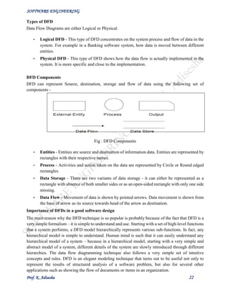
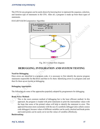
Software Reengineering
Software reengineering is a combination of two consecutive processes i.e. software reverse
engineering and software forward engineering.
Estimation of approximate maintenance cost
It is well known that maintenance efforts require about 60% of the total life cycle cost for a typical
software product. However, maintenance costs vary widely from one application domain to another.
For embedded systems, the maintenance cost can be as much as 2 to 4 times the development cost.
Boehm [1981] proposed a formula for estimating maintenance costs as part of his COCOMO cost
estimation model. Boehm’s maintenance cost estimation is made in terms of a quantity called the
Annual Change Traffic (ACT). Boehm defined ACT as the fraction of a software product’s source
instructions which undergo change during a typical year either through addition or deletion.
ACT = KLOC added + KLOC deleted
KLOCtotal
where, KLOCadded is the total kilo lines of source code added during maintenance.
KLOCdeleted is the total kilo lines of source code deleted during maintenance.
Thus, the code that is changed, should be counted in both the code added and the code deleted. The
annual change traffic (ACT) is multiplied with the total development cost to arrive at the
maintenance cost: maintenance cost = ACT × development cost.
Most maintenance cost estimation models, however, yield only approximate results because they do
not take into account several factors such as experience level of the engineers, and familiarity of the
engineers with the product, hardware requirements, software complexity, etc.
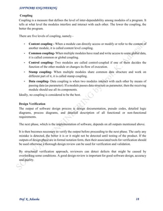
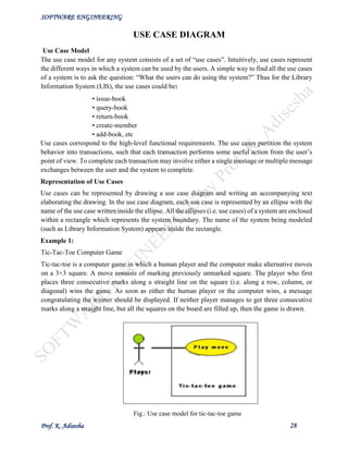
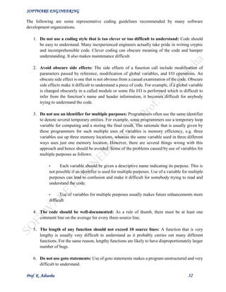
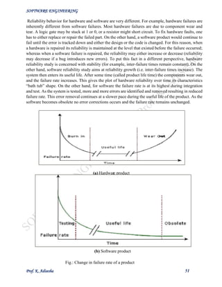
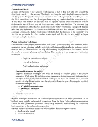
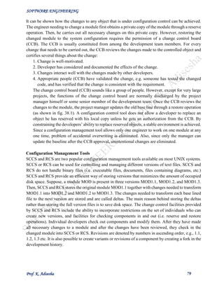
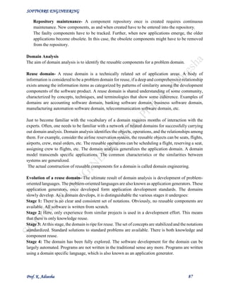
Fig. 25.1: Maintenance process model](https://image.slidesharecdn.com/senotesbyk-200830180551/85/SE-notes-by-k-adisesha-49-320.jpg)


![SOFTWARE ENGINEERING
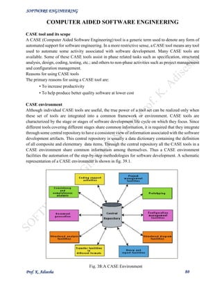
Prof. K. Adisesha 60
Currently two metrics are popularly being used widely to estimate size: lines of code (LOC) and
function point (FP). The usage of each of these metrics in project size estimation has its own
advantages and disadvantages.
Lines of Code (LOC)
LOC is the simplest among all metrics available to estimate project size. This metric is very popular
because it is the simplest to use. Using this metric, the project size is estimated by counting the
number of source instructions in the developed program. Obviously, while counting the number of
source instructions, lines used for commenting the code and the header lines should be ignored.
Determining the LOC count at the end of a project is a very simple job. However, accurate estimation
of the LOC count at the beginning of a project is very difficult. In order to estimate the LOC count
at the beginning of a project, project managers usually divide the problem into modules, and each
module into submodules and so on, until the sizes of the different leaf-level modules can be
approximately predicted. To be able to do this, past experience in developing similar products is
helpful. By using the estimation of the lowest level modules, project managers arrive at the total size
estimation.
Function point (FP)
Function point metric was proposed by Albrecht [1983]. This metric overcomes many of the
shortcomings of the LOC metric. Since its inception in late 1970s, function point metric has been
slowly gaining popularity. One of the important advantages of using the function point metric is that
it can be used to easily estimate the size of a software product directly from the problem
specification. This is in contrast to the LOC metric, where the size can be accurately determined only
after the product has fully been developed. The conceptual idea behind the function point metric is
that the size of a software product is directly dependent on the number of different functions or
features it supports. A software product supporting many features would certainly be of larger size
than a product with less number of features. Each function when invoked reads some input data and
transforms it to the corresponding output data. For example, the issue book feature as shown in fig.
of a Library Automation Software takes the name of the book as input and displays its location and
the number of copies available. Thus, a computation of the number of input and the output data
values to a system gives some indication of the number of functions supported by the system.
Fig. 31.1: System function as a map of input data to output data](https://image.slidesharecdn.com/senotesbyk-200830180551/85/SE-notes-by-k-adisesha-60-320.jpg)
![SOFTWARE ENGINEERING
Prof. K. Adisesha 64
Single variable estimation models provide a means to estimate the desired characteristics of a
problem, using some previously estimated basic (independent) characteristic of the software product
such as its size.
The basic COCOMO model is an example of single variable cost estimation model.
Multivariable estimation models are expected to give more accurate estimates compared to the single
variable models, since a project parameter is typically influenced by several independent parameters.
The intermediate COCOMO model can be considered to be an example of a multivariable estimation
model.
COCOMO MODEL
Organic, Semidetached and Embedded software projects
Boehm postulated that any software development project can be classified into one of the following
three categories based on the development complexity: organic, semidetached, and embedded. In
order to classify a product into the identified categories, Boehm not only considered the
characteristics of the product but also those of the development team and development environment.
Roughly speaking, these three product classes correspond to application, utility and system
programs, respectively. Normally, data processing programs are considered to be application
programs. Compilers, linkers, etc., are utility programs. Operating systems and real-time system
programs, etc. are system programs. System programs interact directly with the hardware and
typically involve meeting timing constraints and concurrent processing.
Boehm’s [1981] definition of organic, semidetached, and embedded systems are elaborated below.
Organic: A development project can be considered of organic type, if the project deals with
developing a well understood application program, the size of the development team is reasonably
small, and the team members are experienced in developing similar types of projects.
Semidetached: A development project can be considered of semidetached type, if the development
consists of a mixture of experienced and inexperienced staff. Team members may have limited
experience on related systems but may be unfamiliar with some aspects of the system being
developed.
Embedded: A development project is considered to be of embedded type, if the software being
developed is strongly coupled to complex hardware, or if the stringent regulations on the operational
procedures exist.
COCOMO
COCOMO (Constructive Cost Estimation Model) was proposed by Boehm [1981]. According to
Boehm, software cost estimation should be done through three stages: Basic COCOMO,
Intermediate COCOMO, and Complete COCOMO.](https://image.slidesharecdn.com/senotesbyk-200830180551/85/SE-notes-by-k-adisesha-64-320.jpg)
![SOFTWARE ENGINEERING
Prof. K. Adisesha 65
Basic COCOMO Model
The basic COCOMO model gives an approximate estimate of the project parameters. The basic
COCOMO estimation model is given by the following expressions:
a
Effort = a х (KLOC) PM Tdev = b x (Effort) Months
1 2 b
1 2
Where
• KLOC is the estimated size of the software product expressed in Kilo Lines of Code,
• a , a , b , b are constants for each category of software products,
1 2 1 2
• Tdev is the estimated time to develop the software, expressed in months,
• Effort is the total effort required to develop the software product, expressed in person
months (PMs).
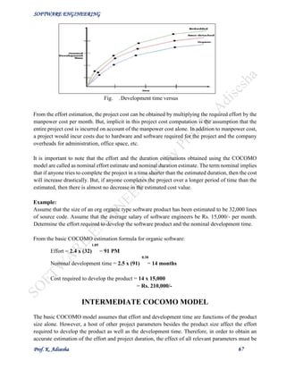
The effort estimation is expressed in units of person-months (PM). It is the area under the person-
month plot (as shown in fig. 33.1). It should be carefully noted that an effort of 100 PM does not
imply that 100 persons should work for 1 month nor does it imply that 1 person should be employed
for 100 months, but it denotes the area under the person-month curve (as shown in fig. 33.1).
Fig. 33.1: Person-month curve
According to Boehm, every line of source text should be calculated as one LOC irrespective of the
actual number of instructions on that line. Thus, if a single instruction spans several lines (say n
lines), it is considered to be nLOC. The values of a , a , b , b for different categories of
1 2 1 2
products (i.e. organic, semidetached, and embedded) as given by Boehm [1981] are summarized
below. He derived the above expressions by examining historical data collected from a large number
of actual projects.
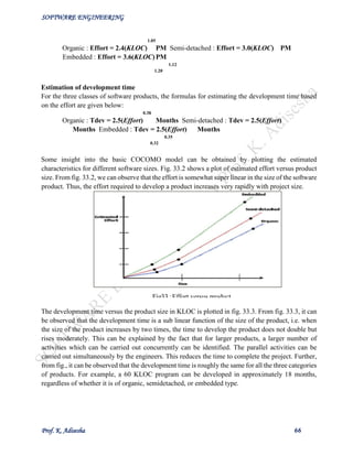
Estimation of development effort
For the three classes of software products, the formulas for estimating the effort based on the code
size are shown below:](https://image.slidesharecdn.com/senotesbyk-200830180551/85/SE-notes-by-k-adisesha-65-320.jpg)

![SOFTWARE ENGINEERING
Prof. K. Adisesha 73
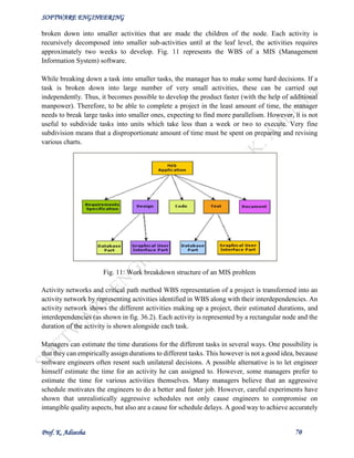
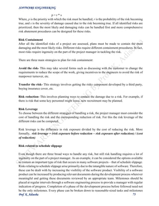
identify parallel activities in a project using a PERT chart. Project managers need to identify the
parallel activities in a project for assignment to different engineers.
Fig.14: PERT chart representation of the MIS problem
Characteristics of a good software engineer
The attributes that good software engineers should possess are as follows:
• Exposure to systematic techniques, i.e. familiarity with software engineering principles.
• Good technical knowledge of the project areas (Domain knowledge).
• Good programming abilities.
• Good communication skills. These skills comprise of oral, written, and interpersonal skills.
• High motivation.
• Sound knowledge of fundamentals of computer science.
• Intelligence.
• Ability to work in a team , etc.
Studies show that these attributes vary as much as 1:30 for poor and bright candidates. An experiment
conducted by Sackman [1968] shows that the ratio of coding hour for the worst to the best
programmers is 25:1, and the ratio of debugging hours is 28:1. Also, the ability of a software engineer
to arrive at the design of the software from a problem description varies greatly with respect to the
parameters of quality and time.
Technical knowledge in the area of the project (domain knowledge) is an important factor
determining the productivity of an individual for a particular project, and the quality of the product
that he develops. A programmer having a thorough knowledge of database application (e.g. MIS)
may turn out to be a poor data communication engineer. Lack of familiarity with the application
areas can result in low productivity and poor quality of the product.
Since software development is a group activity, it is vital for a software engineer to possess three
main kinds of communication skills: Oral, Written, and Interpersonal. A software engineer not only
needs to effectively communicate with his teammates (e.g. reviews, walk throughs, and other team
communications) but may also have to communicate with the customer to gather product
requirements. Poor interpersonal skills hamper these vital activities and often show up as poor](https://image.slidesharecdn.com/senotesbyk-200830180551/85/SE-notes-by-k-adisesha-73-320.jpg)

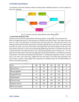
The document discusses software engineering and provides an overview of key concepts. It defines software engineering and discusses its need. It describes characteristics of good software and lists factors like operational, transitional, and maintenance characteristics. It also covers software development life cycles and models like the classical waterfall model. The classical waterfall model divides the life cycle into phases like feasibility study, requirements analysis, design, coding/unit testing, and integration/system testing.