
Recommended
More Related Content
What's hot
What's hot (19)
Similar to Sample:grid converters for microgrids
Similar to Sample:grid converters for microgrids (20)
Recently uploaded
Recently uploaded (20)
Sample:grid converters for microgrids
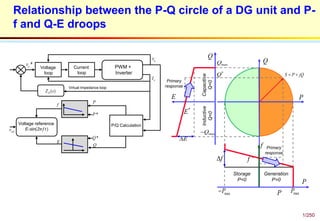
- 1. 1/250 Relationship between the P-Q circle of a DG unit and P- f and Q-E droops Voltage loop Current loop PWM + Inverter P/Q CalculationVoltage reference E-sin(2𝜋𝑓𝑡) Virtual Impedance loop ( )DZ s *ov ov oI P *P *Q Q E f refv Inductive Q<0 Capacitive Q<0 S P jQ Storage P<0 Generation P>0 P Q Q * Q maxQ maxQ f f E * E P PmaxP maxP Primary response Primary response E f
- 2. Decoupled Droop Control Techniques J. Quesada, J.A. Sainz, R. Sebastian, and M. Castro, “Decoupled droop control techniques for inverters in low-voltage AC microgrids,” IEEE 11th International Multi-Conference on Systems, Signals & Devices (SSD), pp. 1-6, 11-14 Feb. 2014. (a) Droop controlled inverter (b) Simplified model of the droop controlled inverter. (c) Control diagram for classic droop. (d) Droop control with an RL coupling impedance. (d) Droop control with decoupling term kc in the feedback matrix. Droop Control Vbus Bridge Basic controlled inverter(BCI) fL fC cV gi Li p qPQ d qE E jE refe reff Droop Control p q refe reff d qE E jE Microgrid MicrogridLZ R j X g d qi i j i coupling point1 Reference syntetizer coupling point E (a) (b) Internal Controller PQ g V ( )G s0 1 0 0 S 0 0 q p k k 0 0 0 0 0 0 S S S S S S e f e reff refe p q ( )G s0 1 0 0 S 0 0 q p k k L L X R Z Z XR Z Z e f e reff refe p q p q ( )G s0 1 0 0 S 0 c q p k k k 0 0 0 0 0 0 S S S S S S e f e reff refe p q
- 3. 3/250 Block Diagram for Classic Droop Scheme ( )G s0 1 0 0 S 0 0 q p k k 0 0 0 0 0 0 S S S S S S e f e reff refe p q 0 0 1 00 0 0 b d d d o bq q q b b ZR i i vdELd L E Zi i vRdt V VL 1 03 0 12 do b qb ip V I iq S
- 4. 4/250 Circuit structure for the n-parallel connected inverters 2015.Line and grid impedance impact on the performances of a parallel connected modular inverter system.pdf Inverter Inverter Inverter 1 1 1, ,a a ai R L 2 2 2, ,a a ai R L , ,an an ani R L 1 1 1, ,c c ci R L , ,cn cn cni R L ,a aR L 1 1 1, ,b b bi R L ae V Cgv inL ini