Download to read offline
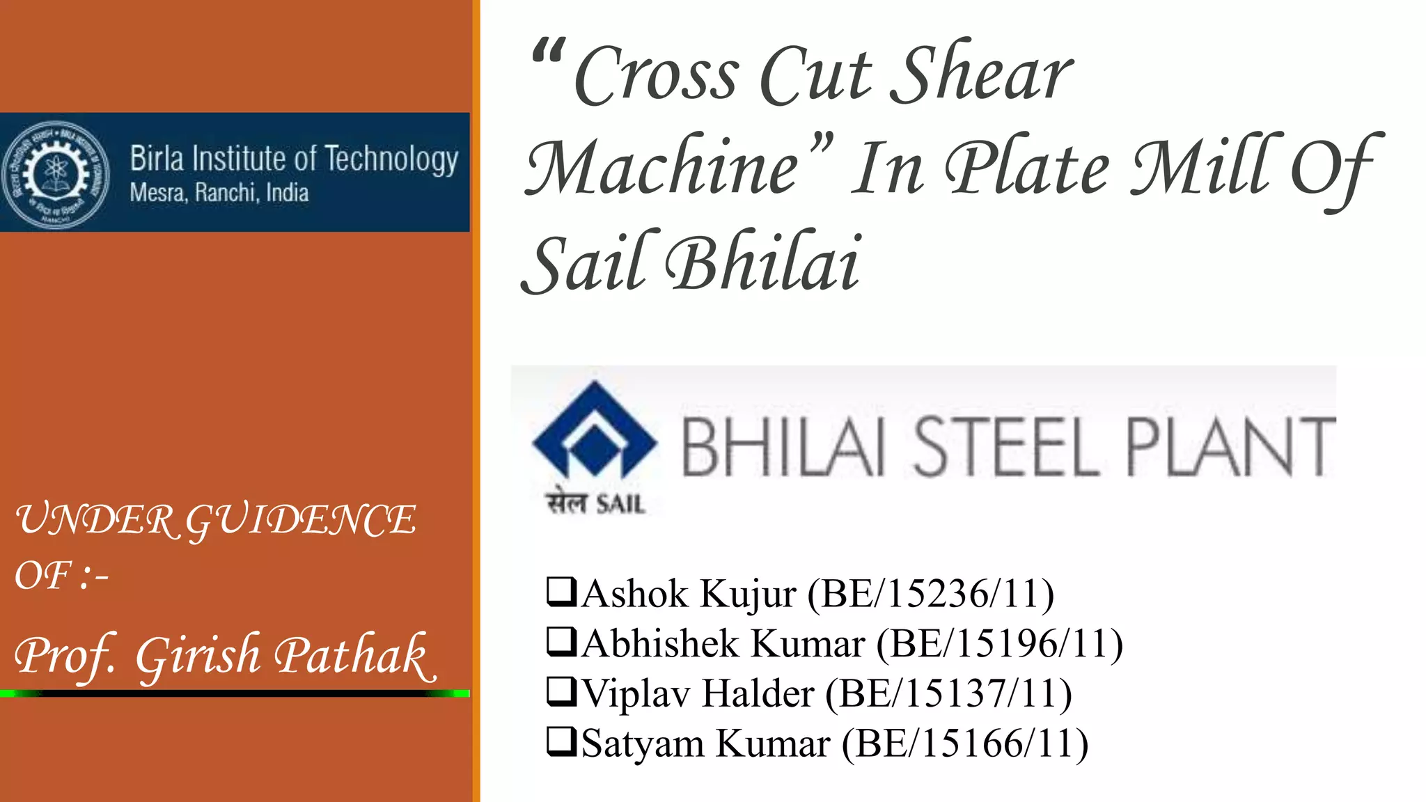
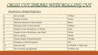
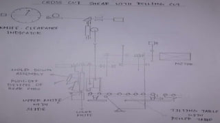
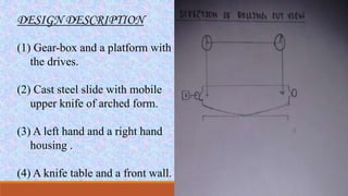
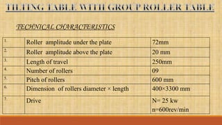
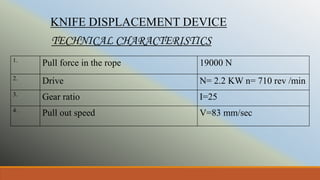
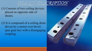
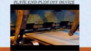
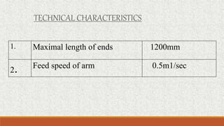
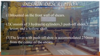


This document describes a student project to study the kinematic mechanism of a cross cut shear machine in the plate mill of Bhilai Steel Plant. It provides background on Bhilai Steel Plant and outlines the objective of studying the cross cut shear machine. It then describes the technical characteristics, design, working, and maintenance of the cross cut shear machine. The conclusion states that the project provided valuable practical experience for the engineering students.


![[Deck] What's New in Spark-Iceberg Integration via DSV2.pptx](https://cdn.slidesharecdn.com/ss_thumbnails/deckwhatsnewinspark-icebergintegrationviadsv2-260210005337-25955b12-thumbnail.jpg?width=640&height=640&fit=bounds)


