The document provides an overview of measurement technology, focusing on sensors and instrumentation within mechatronics. It covers various types of sensors, measurement systems, and the principles of error classification, analysis, and signal conditioning. Additionally, it outlines the characteristics of sensors and transducers, including static and dynamic features essential for accurate measurement.
![Dynamic Response of Zero-order Instruments
If all the coefficients a1 ... an other than ao in equation (2) are assumed zero, then:
aoqo = boqi or qo = boqi / ao = Kqi -------------(3)
K = bo / ao
where K is a constant known as the instrument sensitivity as defined earlier. Any instrument
that behaves according to equation (3) is said to be of zero order type. Following a step change
in the measured quantity at time t, the instrument output moves immediately to a new value at
the same time instant t.
Dynamic Response of a First Order Instrument:
If all the coefficients a2 ...an except for ao and a1 are assumed zero in equation (2) then:
a1dqo + aoqo = boqi ----------------(4)
dt
Any instrument that behaves according to equation (4) is known as a first order instrument. If
d/dt is replaced by the D operator in equation (4), we get:
a1Dqo+aoqo = boqi
and rearranging this then gives qo = (bo / ao ) qi ------------(5)
[1+(a1/ao)D]
Defining K = bo/ao as the static sensitivity and ԏ = a1/ao as the time constant of the system,
equation (5) becomes:
qo = K qi -----------------(6)
1+ԏD
If equation (6) is solved analytically, the output quantity qo in response to a step change in qi at
time t varies with time in the manner
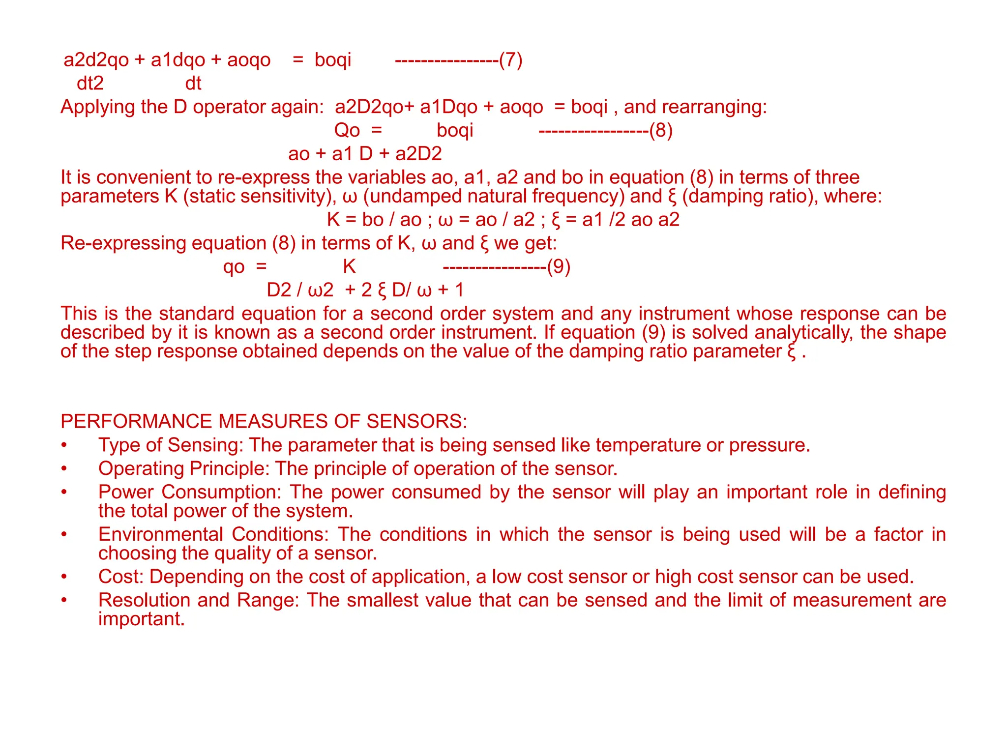
Dynamic Response of Second Order Instrument :
A second order instrument is defined as one that follows the equation](https://image.slidesharecdn.com/siunit1-240801030929-f8302160/75/S-I-Introduction-to-sensor-and-transducer-pptx-28-2048.jpg)