Rotary Gear Type Pump Whitepaper

Gear pump operation & maintenance. REF: https://bin95.com/vocational-training/maintenance/reliability-training.htm A gear pump uses two meshing, toothed cogs to force liquid from the inlet of the pump through to the outlet. Being a positive displacement pump there deliver very precise quantities for each revolution, and this means they have good dosing characteristics regardless of their speed or the pressure into which they discharge. Keywords: internal, external teeth, pressure relief, viscosity. Excerpt: "The design of a gear pump lends itself to use with clean liquids. Ensure they draw liquid from well above the bottom of the supply tank in clear liquid space. Both low and high viscosity liquids can be pumped. If food grade products sensitive to shear (i.e., where the churning action of the pump breaks cells and fibers) are to be pumped the size of the pump will need to be increased and the speed reduced."

Recommended
Recommended
More Related Content
Similar to Rotary Gear Type Pump Whitepaper
Similar to Rotary Gear Type Pump Whitepaper (20)
More from Business Industrial Network
More from Business Industrial Network (20)
Recently uploaded
Recently uploaded (20)
Rotary Gear Type Pump Whitepaper
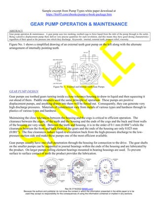
- 1. Rev III (7/16/2022 BIN95.com) Because the authors and publisher do not know the context in which the information presented in the white paper is to be used they accept no responsibility for the consequences of using the information contained or implied in any sections. Sample excerpt from Pump Types white paper download at https://bin95.com/ebooks/pump-e-book-package.htm GEAR PUMP OPERATION & MAINTENANCE ABSTRACT Gear pump operation & maintenance. A gear pump uses two meshing, toothed cogs to force liquid from the inlet of the pump through to the outlet. Being a positive displacement pump there deliver very precise quantities for each revolution, and this means they have good dosing characteristics regardless of their speed or the pressure into which they discharge. Keywords: internal, external teeth, pressure relief, viscosity. Figure No. 1 shows a simplified drawing of an external teeth gear pump on the left along with the alternate arrangement of internally pointing teeth. Figure No. 1. External and Internal Teeth Gear Pumps GEAR PUMP DESIGN Gear pumps use toothed gears turning inside a close tolerance housing to draw-in liquid and then squeezing it out ahead of them. Paddle steamers used the same principle of operation. These pumps are positive displacement pumps, and anything drawn into them will be forced out. Consequently, they can generate very high discharge pressures. Materials of construction vary from metals of various types and hardness through to plastics of various types and hardness. Maintaining the close tolerances between the housing and the cogs is critical to efficient operation. The clearance between the edges, of the teeth and the housing and the ends of the cogs and the back and front walls of the housing are very small. Between the teeth and housing, it is in the order of 0.1 mm (0.004”) while the clearances between the front and back faces of the gears and the ends of the housing are only 0.025 mm (0.001”). The fine clearances reduce liquid re-circulation back from the high-pressure discharge to the low- pressure suction side and make these pumps one of the most efficient available. Gear pumps usually have one shaft penetration through the housing for connection to the drive. The gear shafts on the smaller pumps can be supported in journal bearings within the ends of the housing and are lubricated by the product. On larger pumps rolling element bearings mounted in bearing housings are used. To prevent surface to surface contact of teeth the product provides the lubrication.
- 2. Rev III (7/16/2022 BIN95.com) Because the authors and publisher do not know the context in which the information presented in the white paper is to be used they accept no responsibility for the consequences of using the information contained or implied in any sections. GEAR PUMP OPERATION & MAINTENANCE (Cont.) GEAR PUMP USES The design of a gear pump lends itself to use with clean liquids. Ensure they draw liquid from well above the bottom of the supply tank in clear liquid space. Both low and high viscosity liquids can be pumped. If food grade products sensitive to shear (i.e., where the churning action of the pump breaks cells and fibers) are to be pumped the size of the pump will need to be increased and the speed reduced. The design also produces good suction characteristics, and they can be used to draw clean, low viscosity liquids from a good depth or distance. Where high viscosity liquids are pumped, or if drawing from a depth or distance, make it easy for the liquid to flow into the pump. Install large diameter suction lines, keep them short and where possible always put the pump lower than the supply tank so the suction is under positive head pressure from the stored liquid. The very fine tolerances prevent pumping anything with a solid or particulate, as it would be squashed between the teeth and destroy the pump. If there is risk of solids being drawn into the pump it is necessary to install a suction line strainer that can be easily cleaned. Use as fine mesh screen as is possible without greatly increasing the suction pressure loses else the pump will cavitate. If the particulate is so fine that it passes through the screen it is better to choose a different design of pump. Gear pumps provide consistent quantities of liquid per rotation. The precise nature of the delivery regardless of the pressure head makes them good chemical additive dosing pumps provided material compatibility issues are addressed.
- 3. Rev III (7/16/2022 BIN95.com) Because the authors and publisher do not know the context in which the information presented in the white paper is to be used they accept no responsibility for the consequences of using the information contained or implied in any sections. GEAR PUMP OPERATION & MAINTENANCE (Cont.) GEAR PUMP INSTALLATIONS When using a gear pump a pressure relief valve must be fitted to protect the pump if deadheaded against a closed valve or blockage. The PRV can be piped back to the suction side of the pump or into the supply tank. Pumps driven by belt drives have the added protection that the belts will slip in the pulleys if the pump is deadheaded. Ensure bearings with a heavy-duty radial load carrying ability are installed if the pump is to be belt driven. If a drive coupling is used between the motor and the pump it is critical to align the shafts precisely to within 0.05 mm (0.002”) from motor shaft end to pump shaft end using laser or reverse dial indicator methods. Shaft misalignment produces orbital motion that loads the bearings and distorts the shaft as it turns. Flexible shaft couplings will transmit these loads. These pumps require solid, firm mounts on solid metal bases and plinths. If direct in-line drive through a shaft coupling is used the entire pump set must be mounted on a solid steel frame with pump feet positions machined flat to within 0.025 (0.001”) tolerance MAINTENANCE ISSUES Gear pumps require good, robust installation, a PRV to protect the pump from overpressure and an assured supply of clean liquid. Those with outboard bearings require the bearings to be lubricated. Mechanical seals introduce their own set of problems and if possible, select pumps that do not use them. If mechanical seals are fitted it becomes critical that shafts run true, and the process pressures and flows are steady and do not fluctuate wildly to load up the bearings and gear teeth unevenly. The gear teeth must not be run dry. Unlubricated teeth will rub together and wear away. If these pumps are run dry and temperatures rise the cogs will expand and start rubbing on the housing. This will tear-up the housing and teeth. Either the pump is destroyed, or the fine housing clearances are lost which then allows recirculation within the pump. The best protection against dry running is to install a flow switch in the suction line that turns power off to the pump if there is no flow. Drop-off in pumping efficiency can be due to internal wear increasing the clearances or the pressure relief valve passing. Sample excerpt from Pump Types white paper download at https://bin95.com/ebooks/pump-e-book-package.htm