Downloaded 115 times


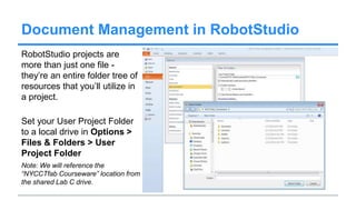
![Document Management in RobotStudio
When you save your
RobotStudio file you are
saving as a RobotStudio
Station file (*.rsstn) - this file
typically goes in the Stations
sub-folder of your User
Project Folder.
Title your Station
[yourSurname]_pen.rsstn.](https://image.slidesharecdn.com/roboticslecture02-140504142327-phpapp01/85/Robotics-lecture-02-8-320.jpg)


1. The document discusses how to set up an industrial robotic station in RobotStudio, including creating a station, importing robot and controller models, setting tool centers, creating targets and paths, and simulating a program. 2. Key steps covered are creating a station, importing CAD files, setting tool centers of points and frames, creating workobjects, targets and paths, and synchronizing the program to the virtual controller for simulation. 3. Simulation and jogging methods are described to test the robot program and motion.