This document provides a 3-sentence summary of the contents of an operator guide for the M2000 system:
The guide contains 7 chapters that describe various functions and operations of the M2000 system, including connecting network elements, managing topology, handling alarms, monitoring performance, managing configurations, and other maintenance and management tasks. Each chapter covers topics such as related terminology, operational processes, querying and browsing data, setting parameters, and more. The document is intended to help users understand and utilize the various capabilities of the M2000 system.
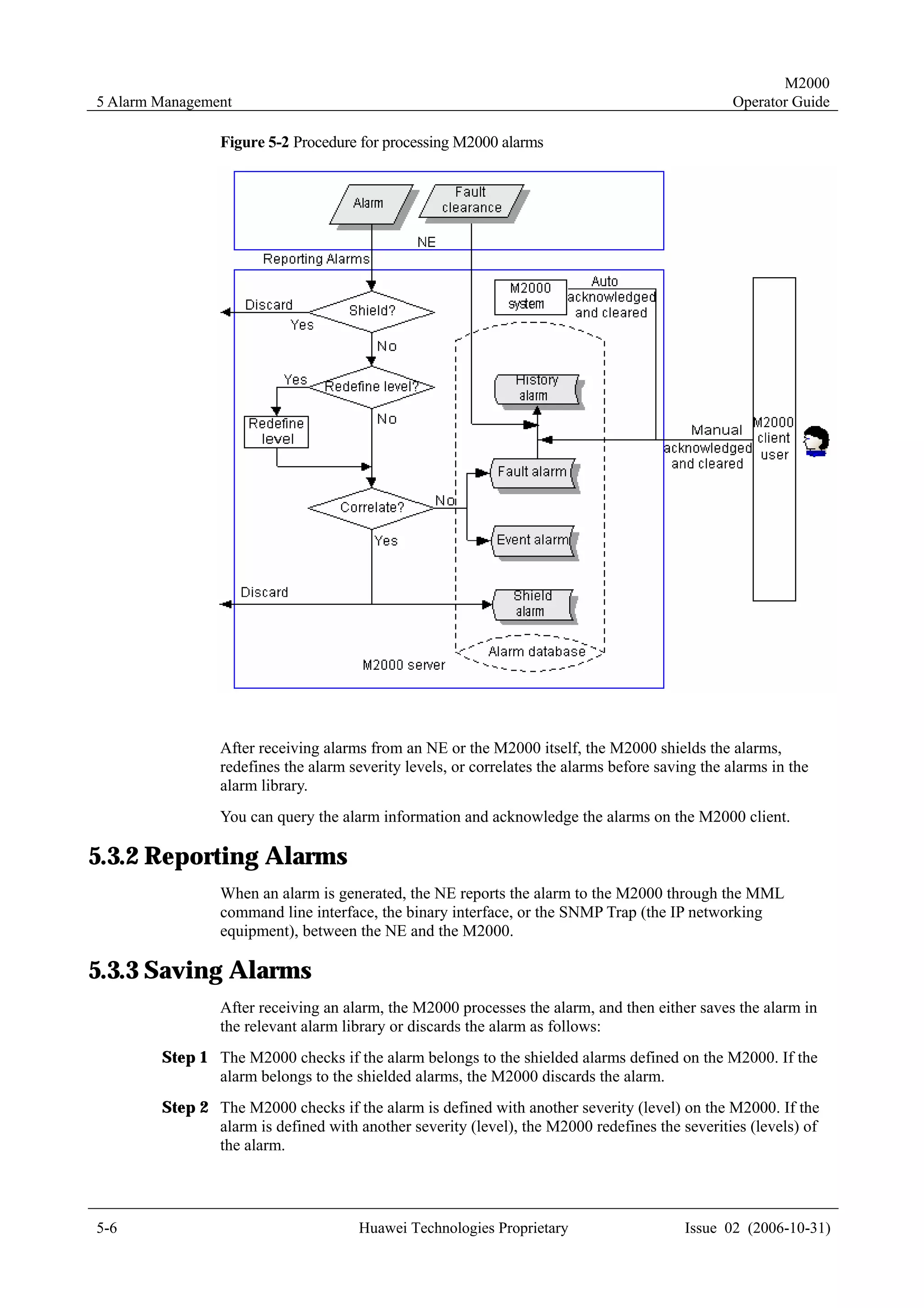
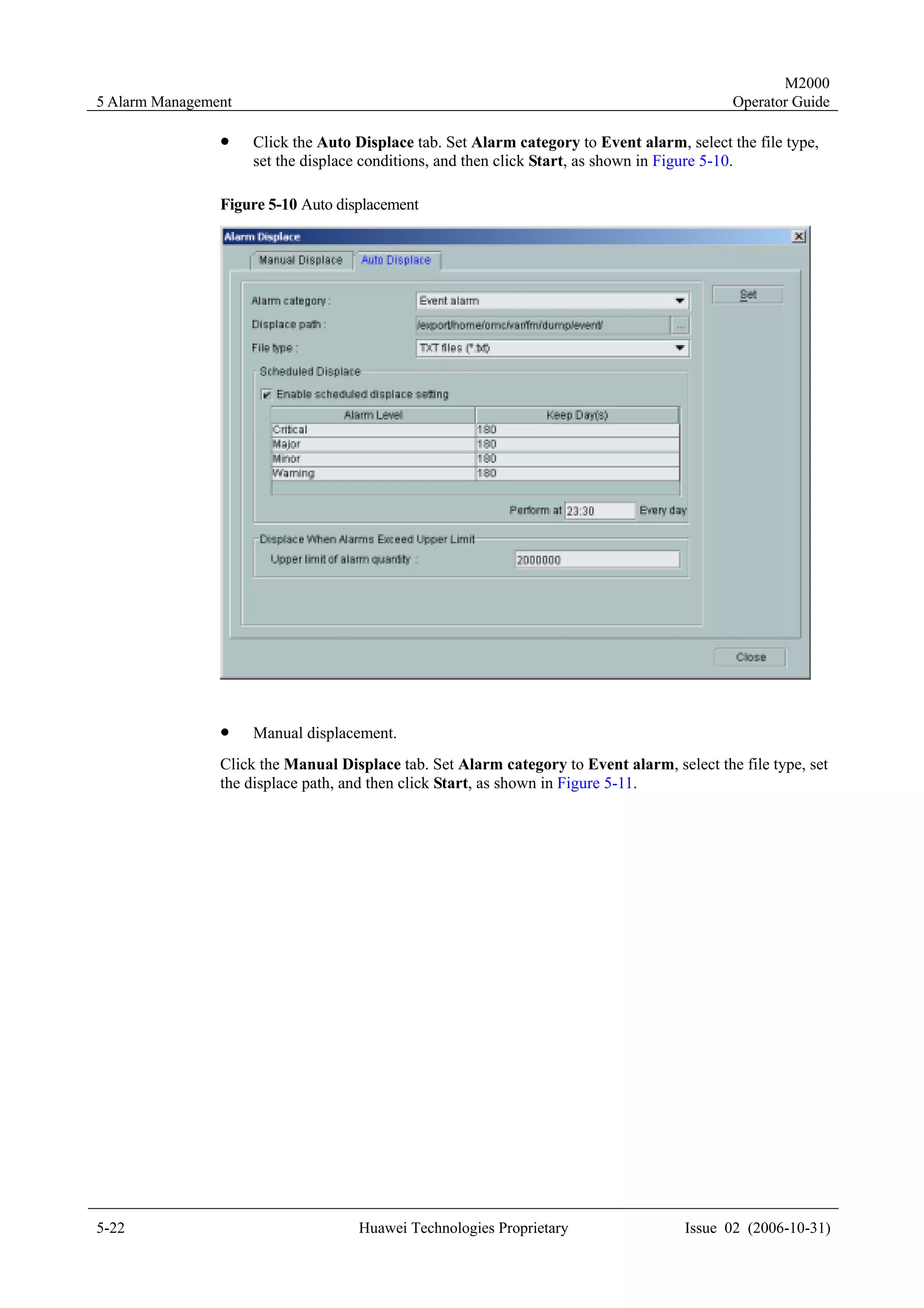
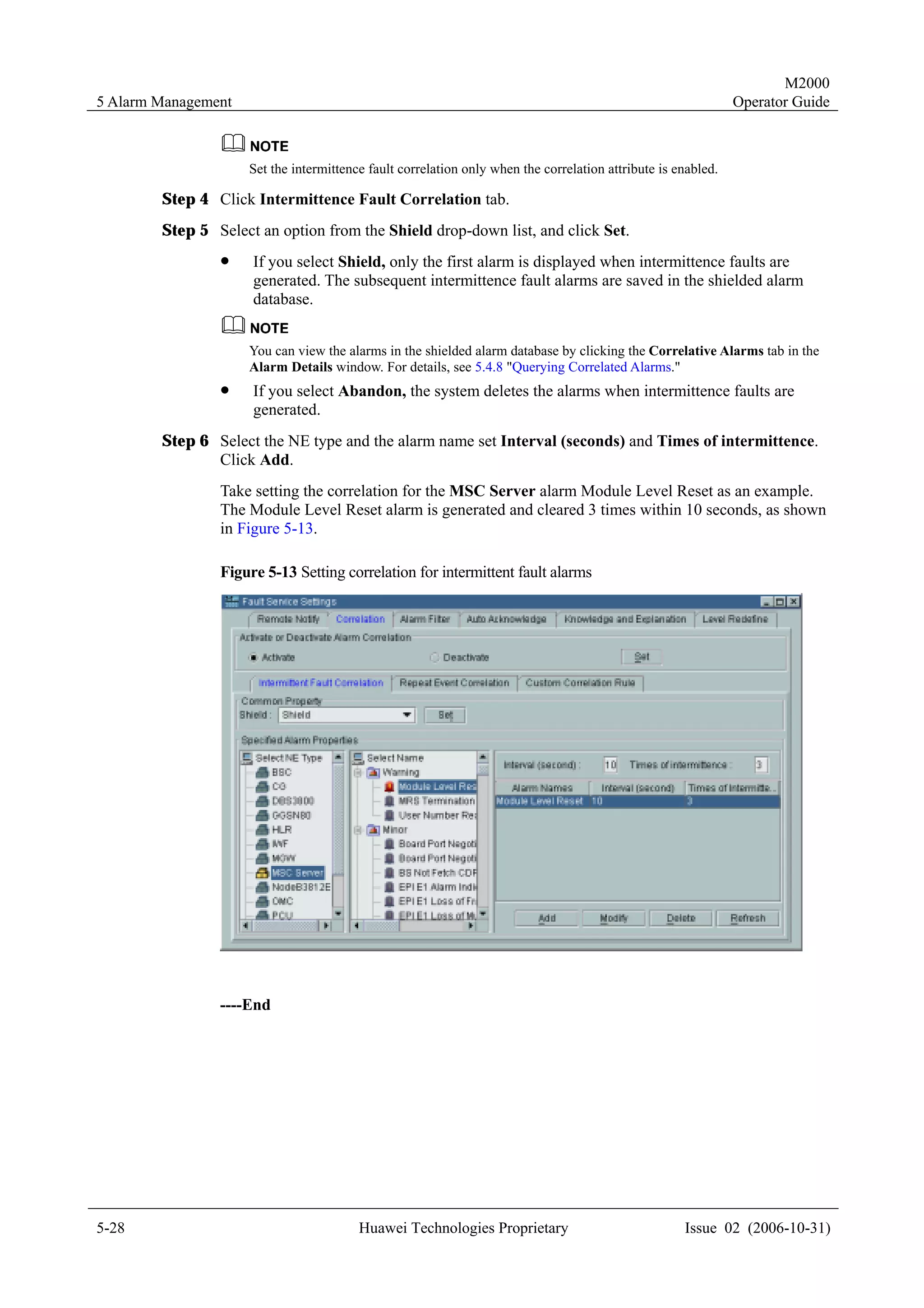
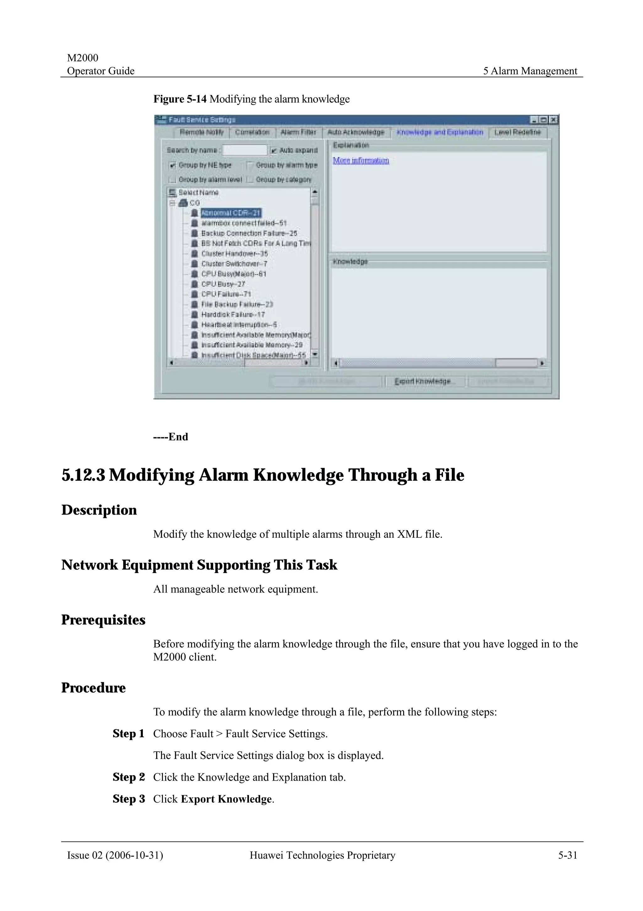
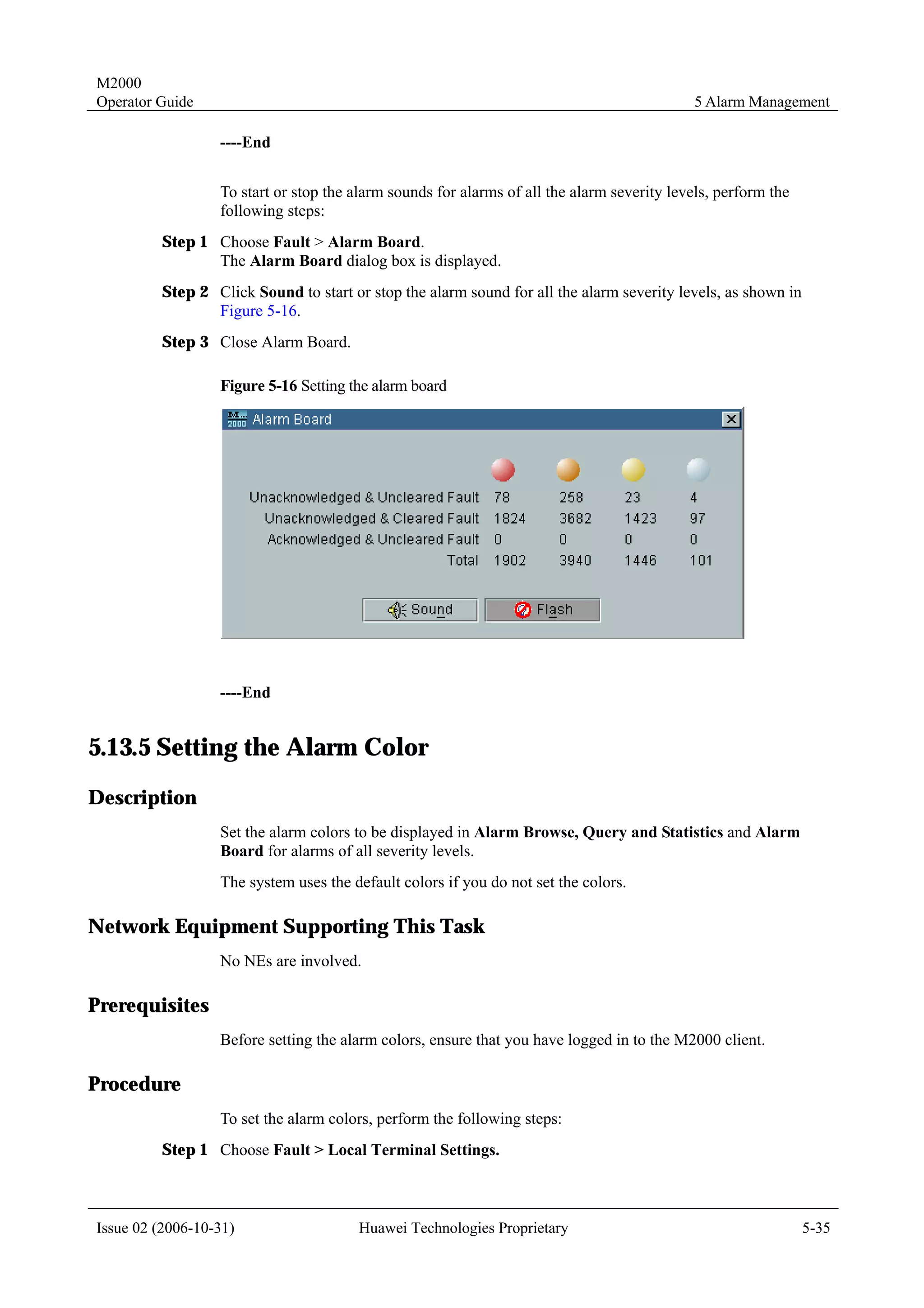
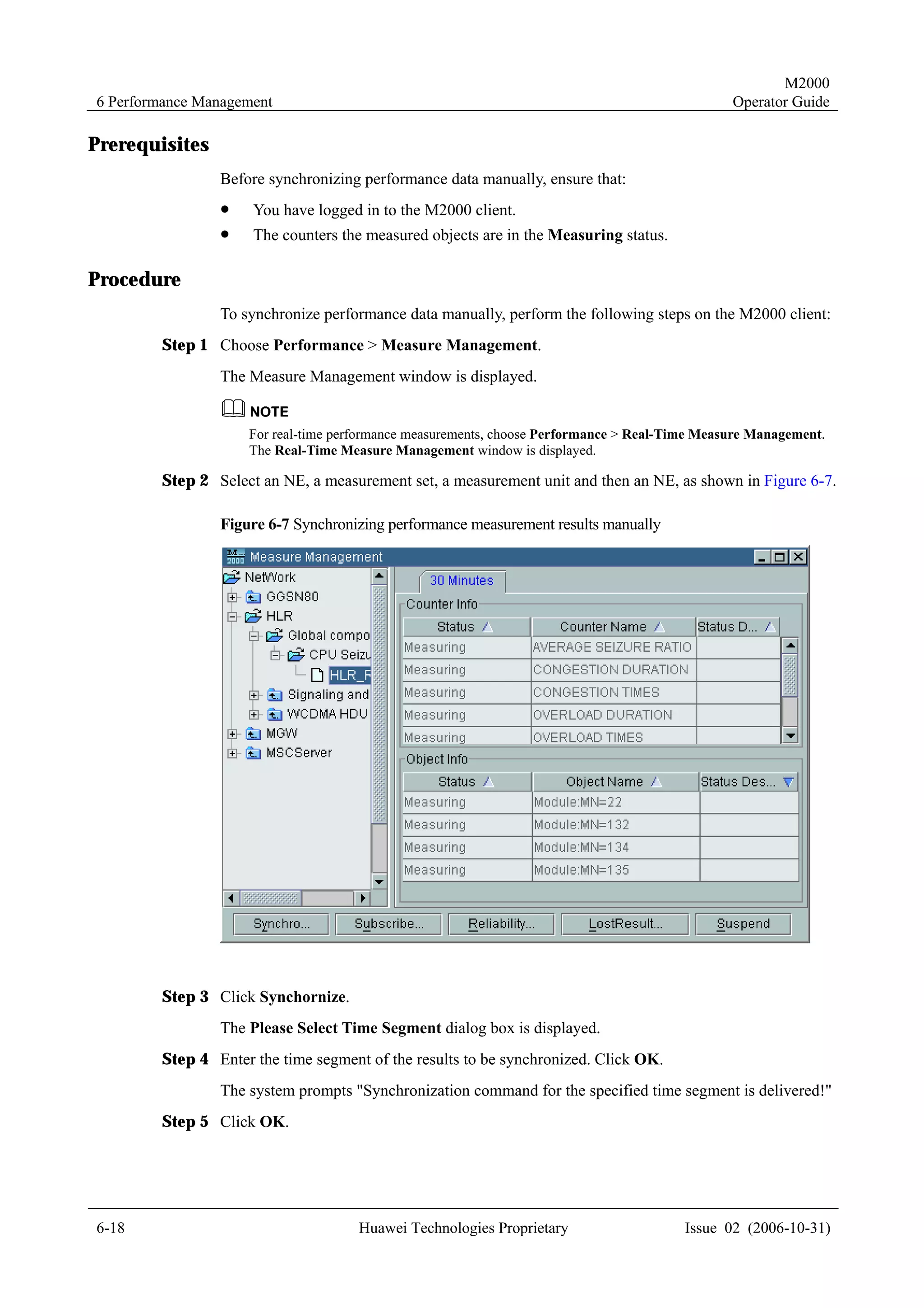
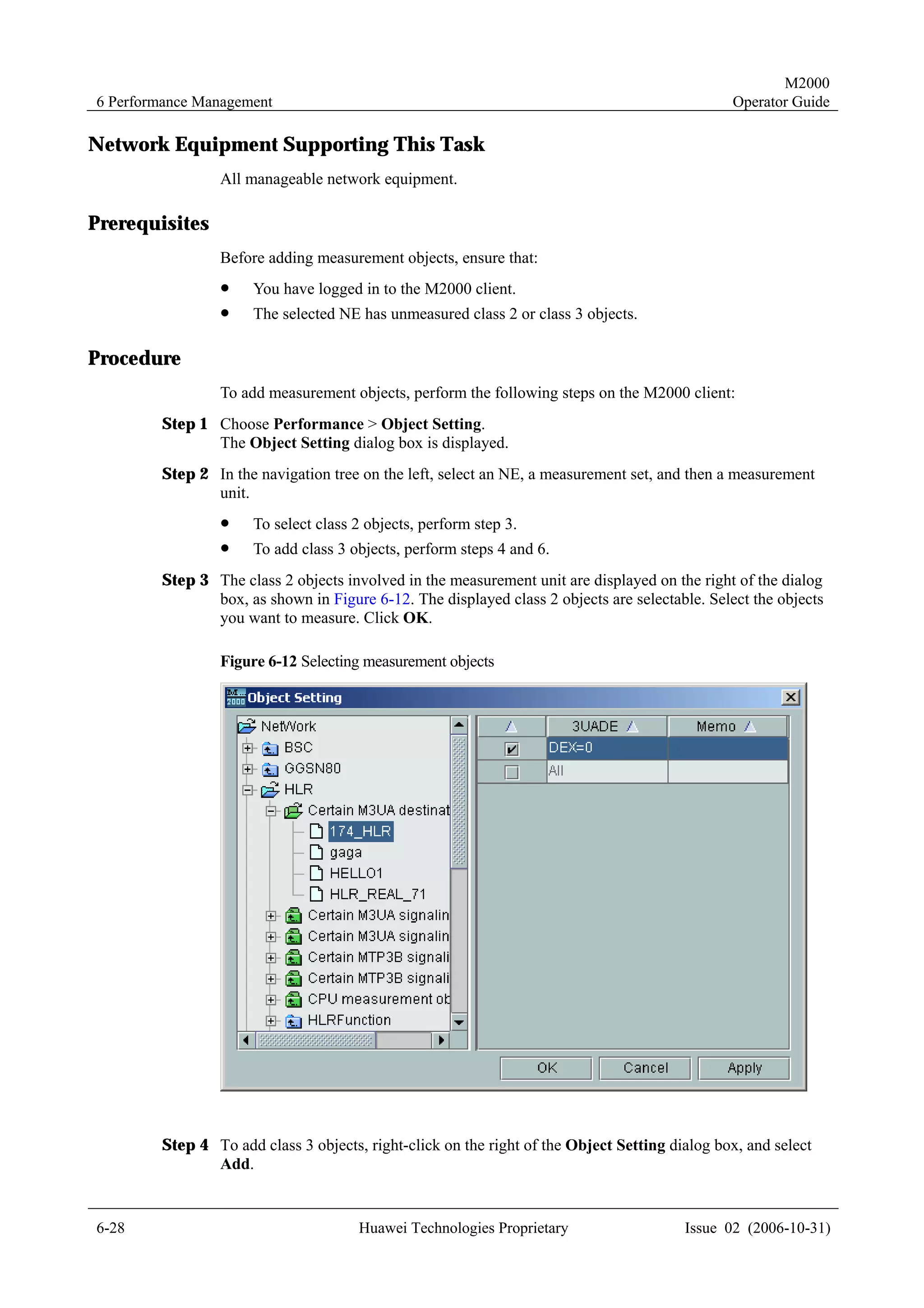
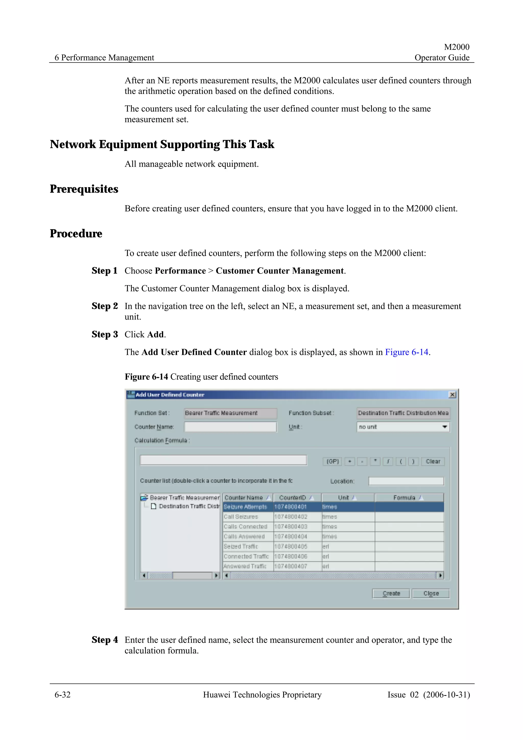
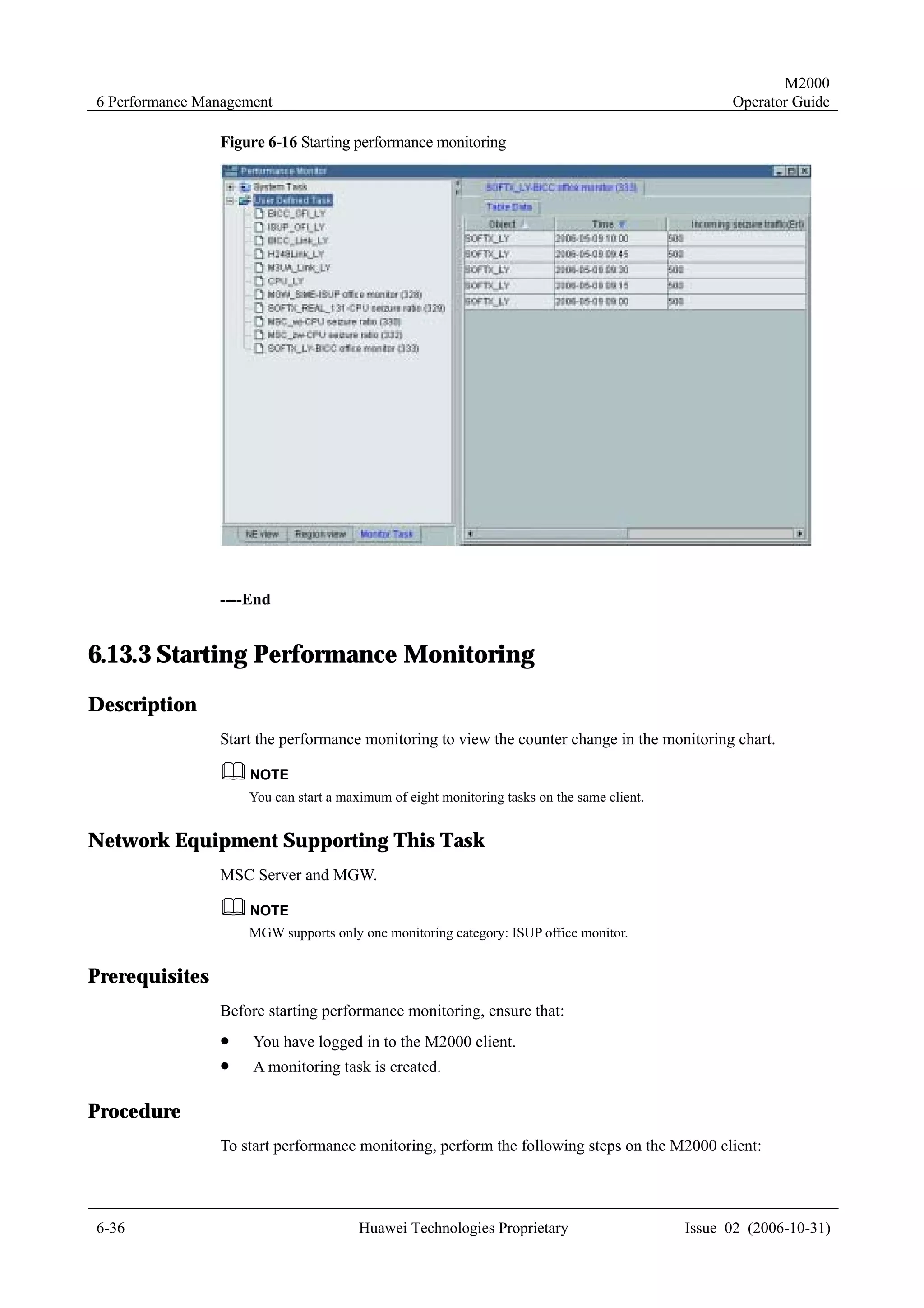
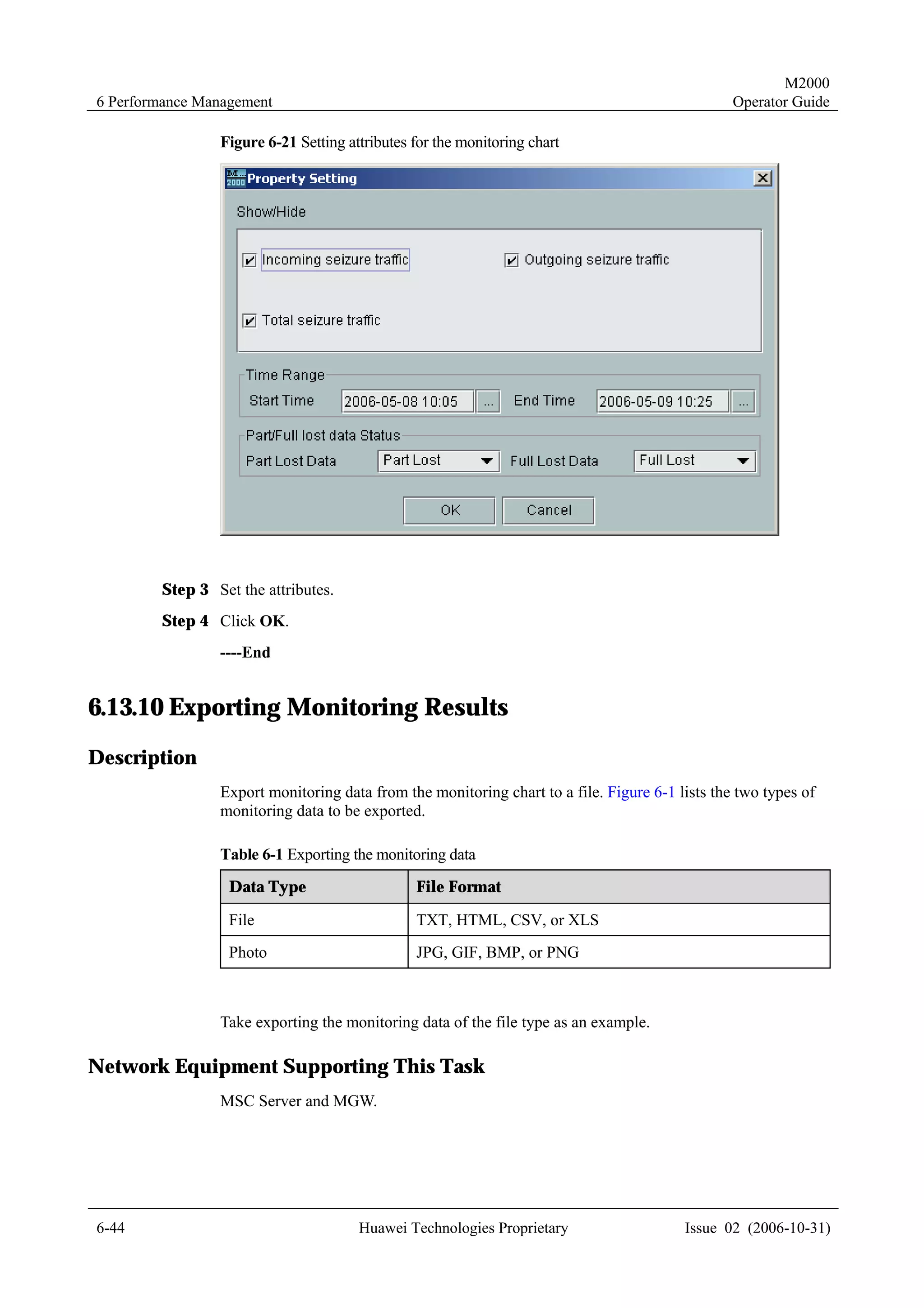
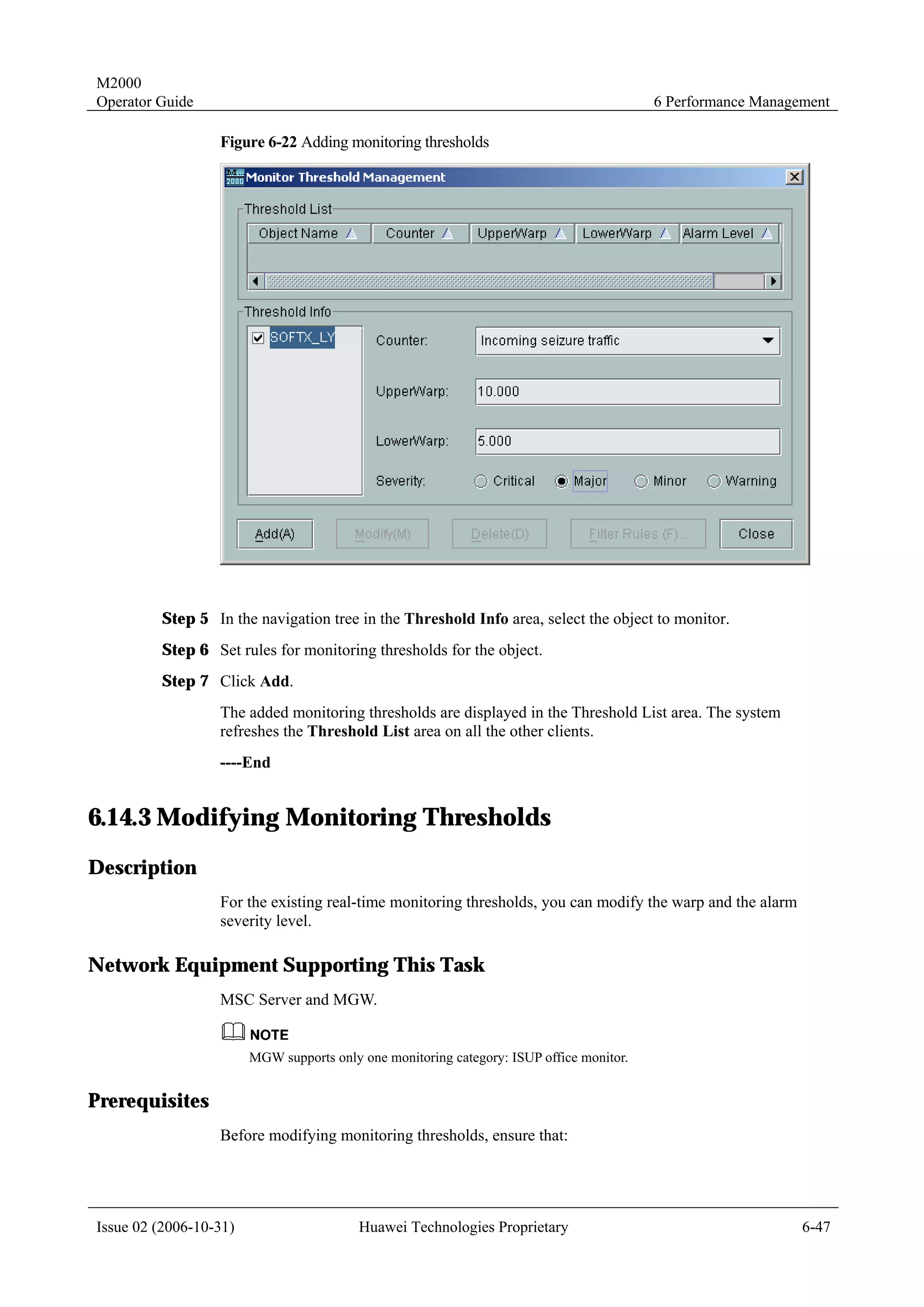
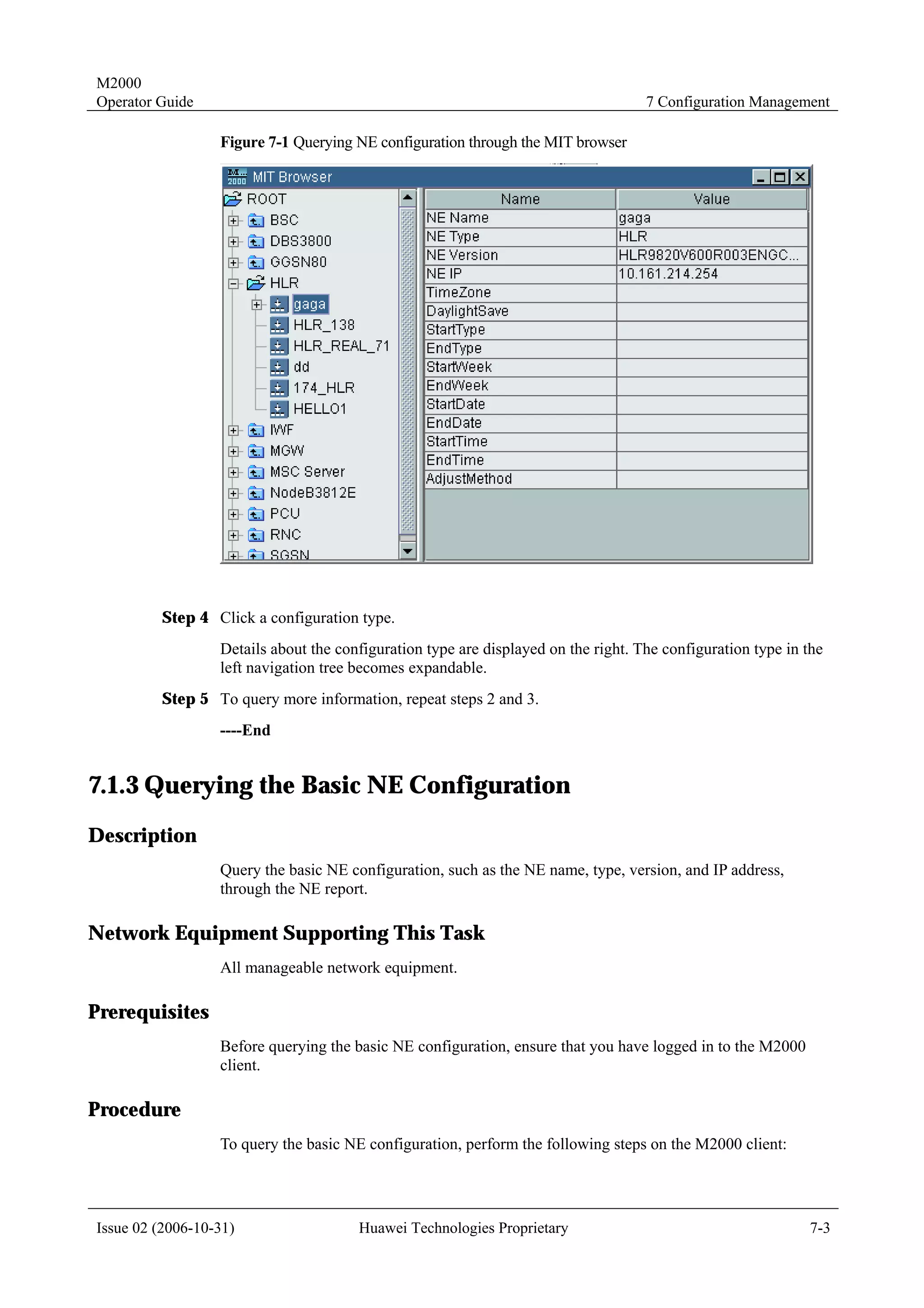
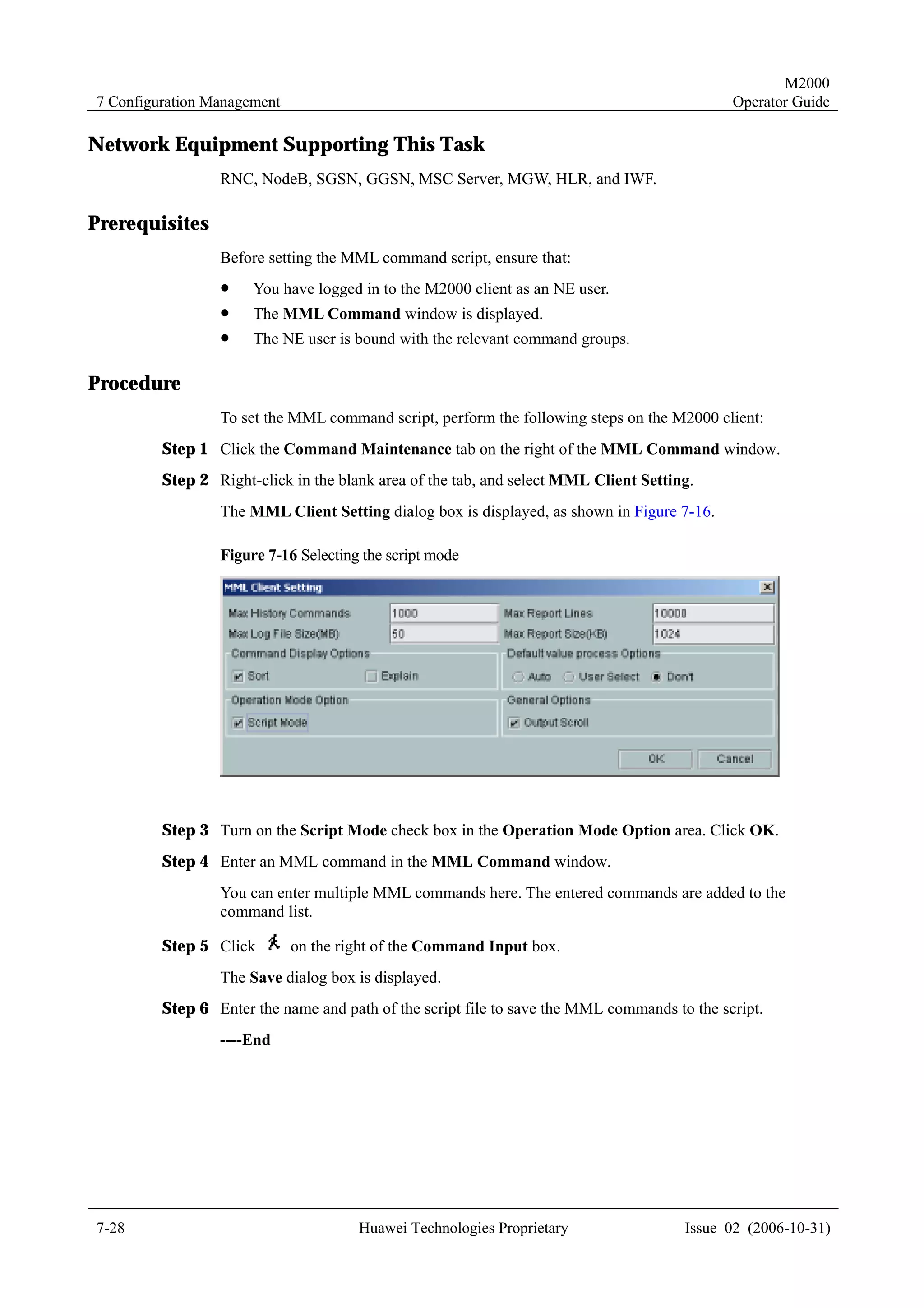
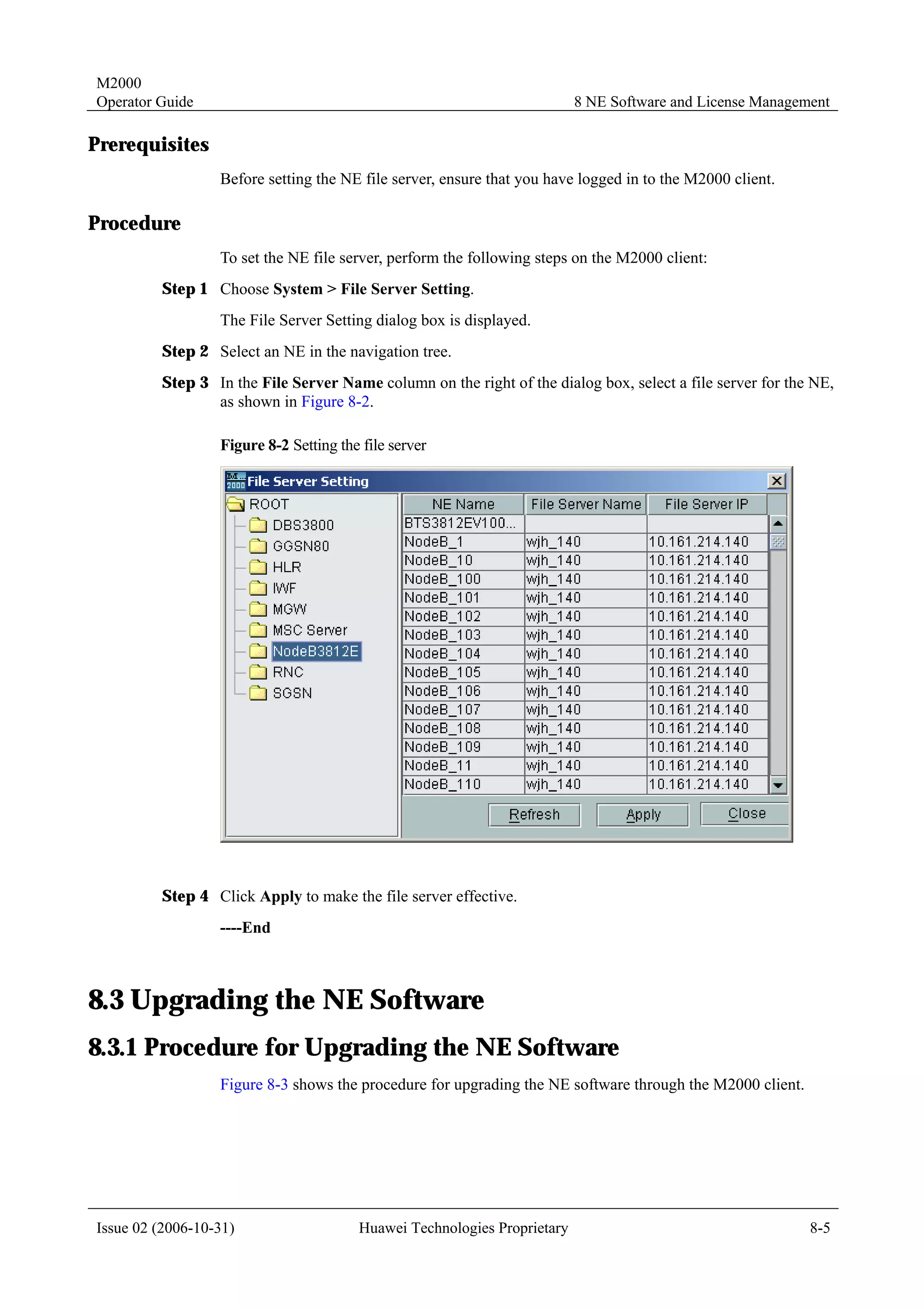
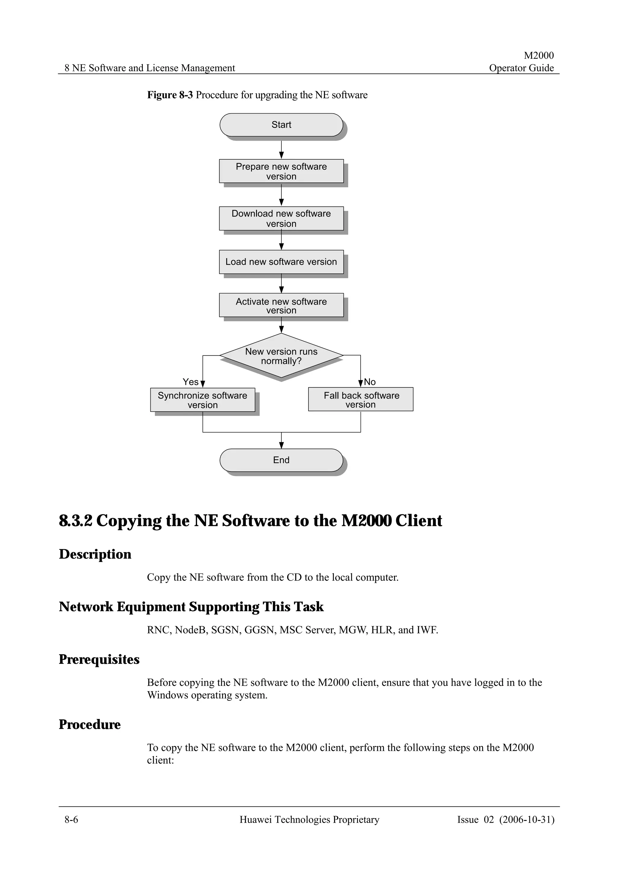
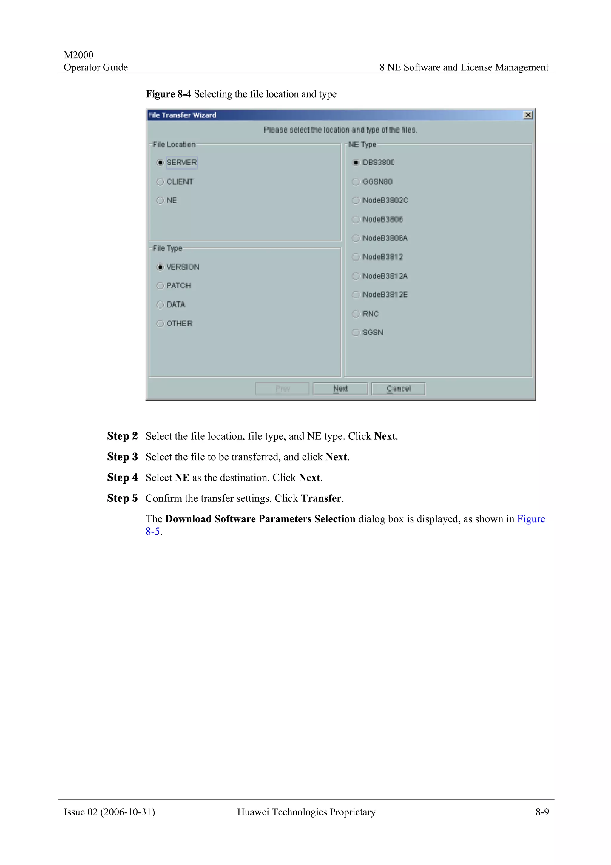
![M2000
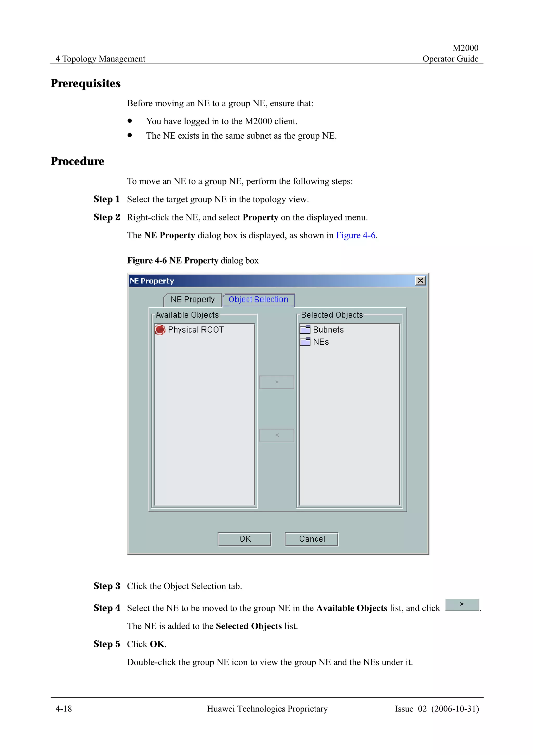
Operator Guide 4 Topology Management
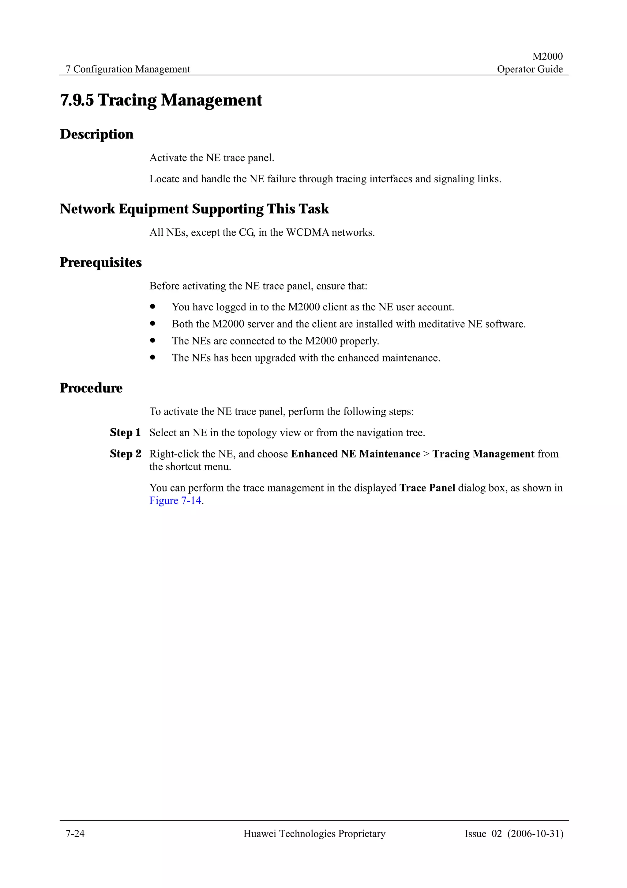
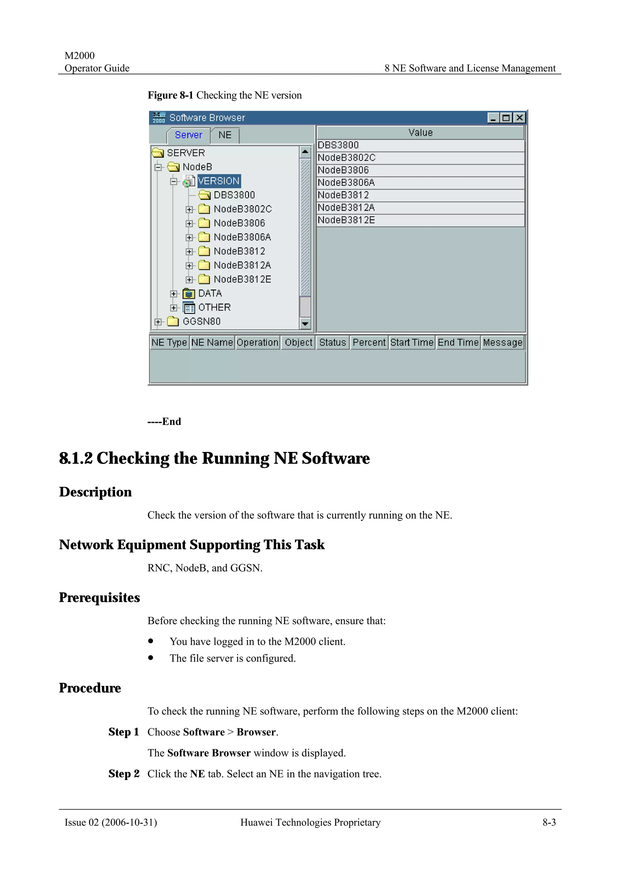
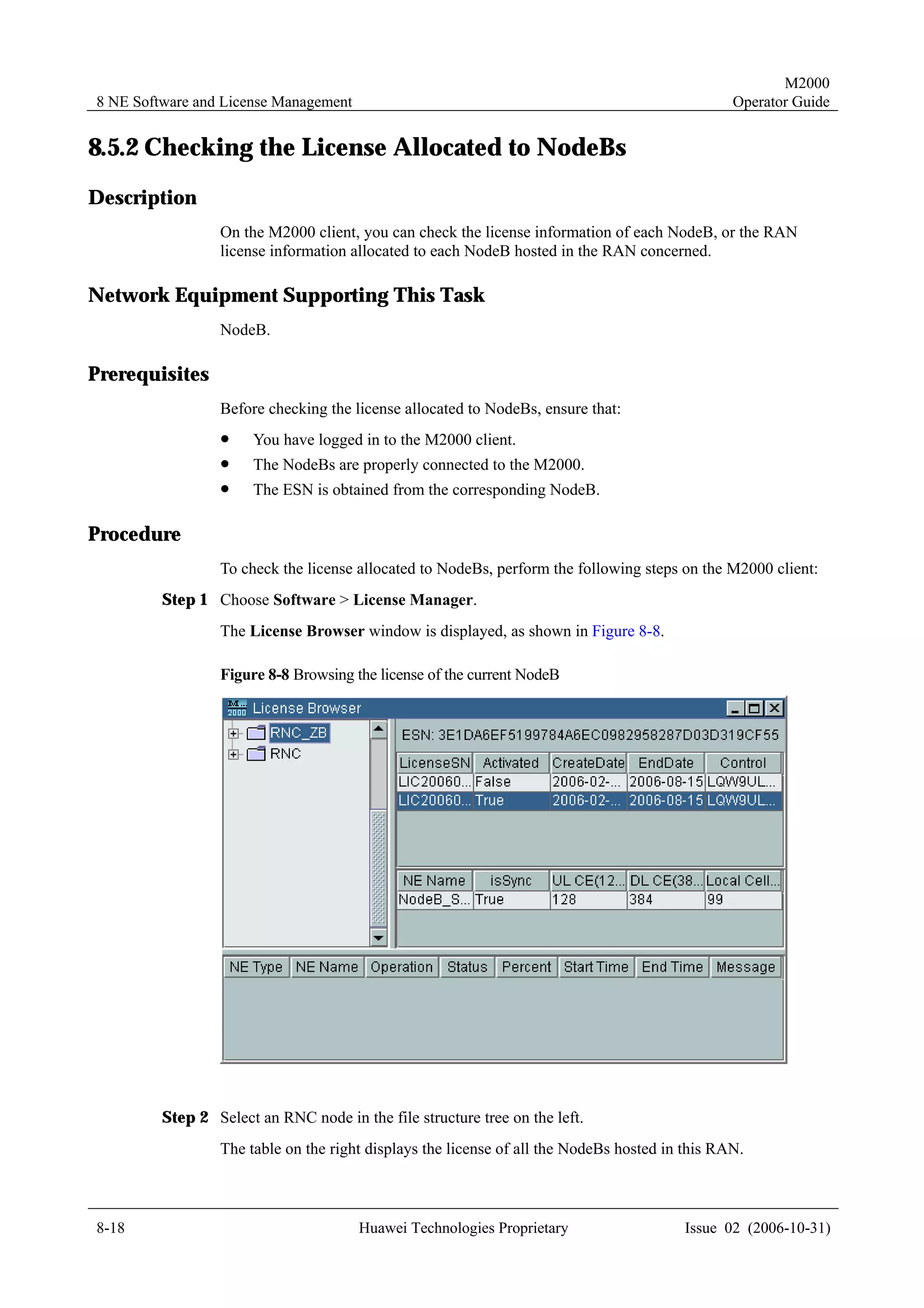
4.1.7 Templates for Creating Physical NEs in Batches
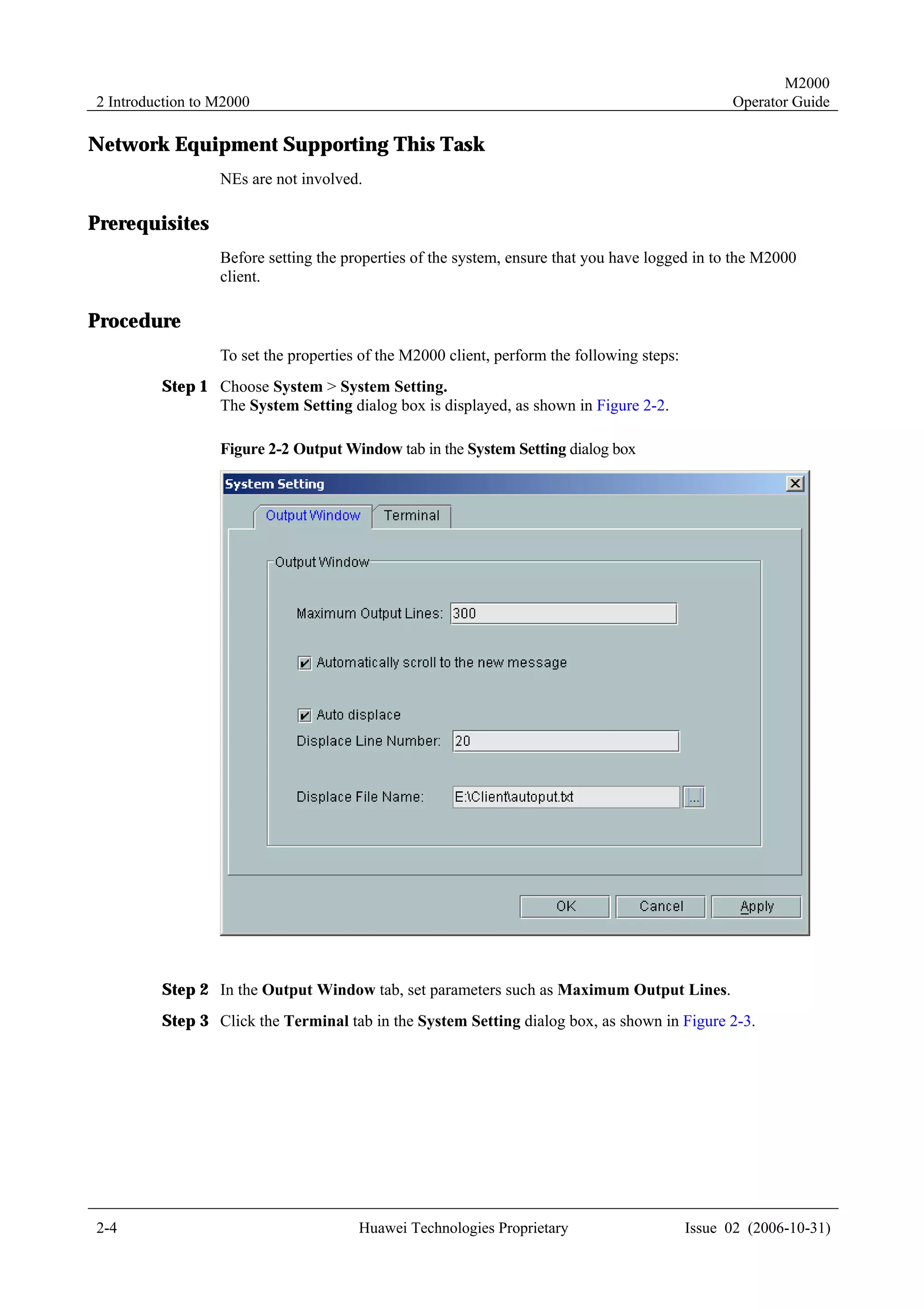
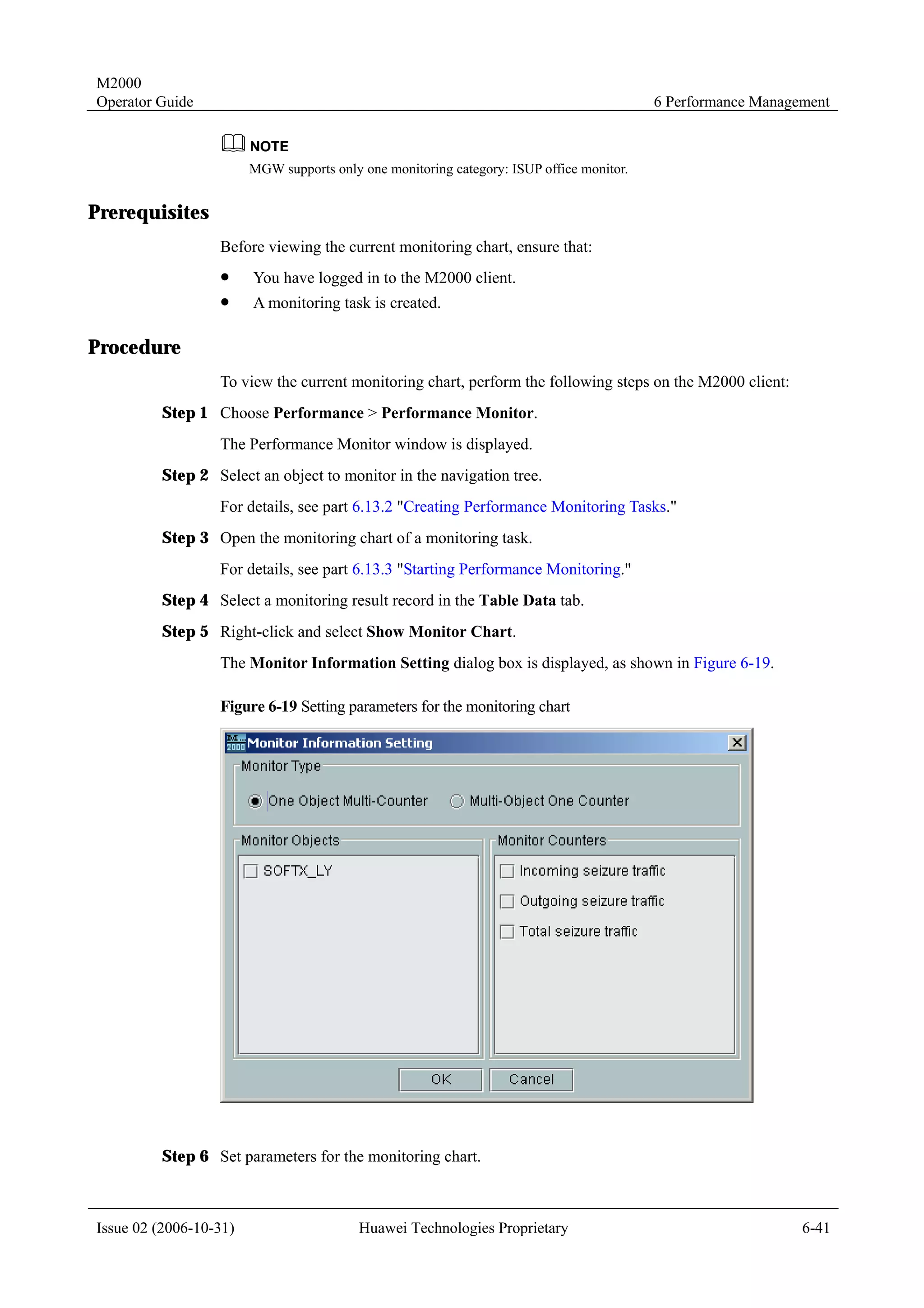
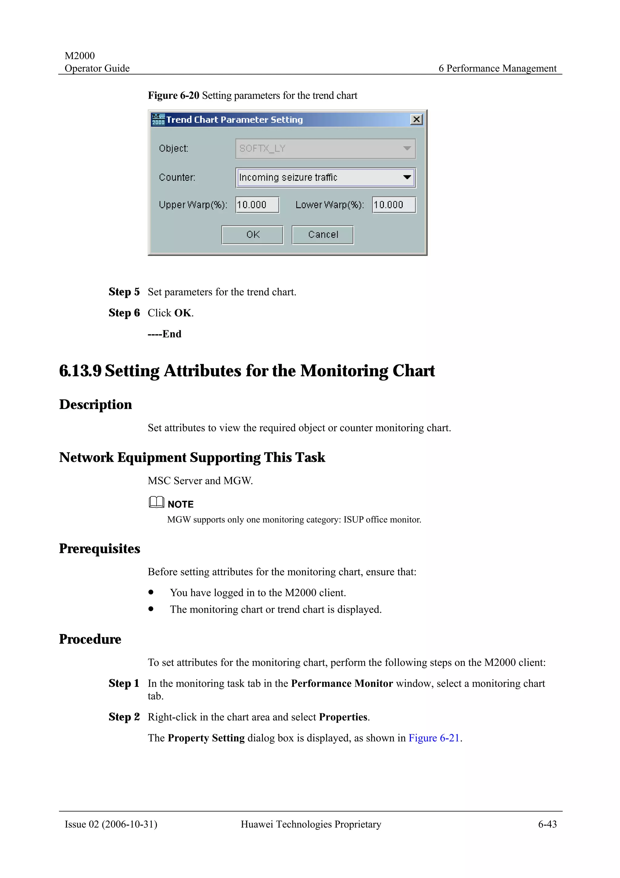
Meaning
To create NEs in batches on the M2000 client, you must create a script file manually and
perform the creation in bathes through executing the script.
Templates for creating physical NEs in batches are the standard templates provided by the
M2000 client. You only need to export the template, and then enter the information of the NEs
to be created. Two formats of templates are available: INI and CSV.
Templates for creating physical NEs in batches are the standard templates provided by the
M2000 client. Two formats of templates are available: INI and CSV.
Templates in the CSV Format
The templates in the CSV format apply only to the NEs in WCDMA networks.
Use the Microsoft Excel to edit the templates in the CSV format. All the NEs apply the same
parameter group, as shown in Figure 4-1.
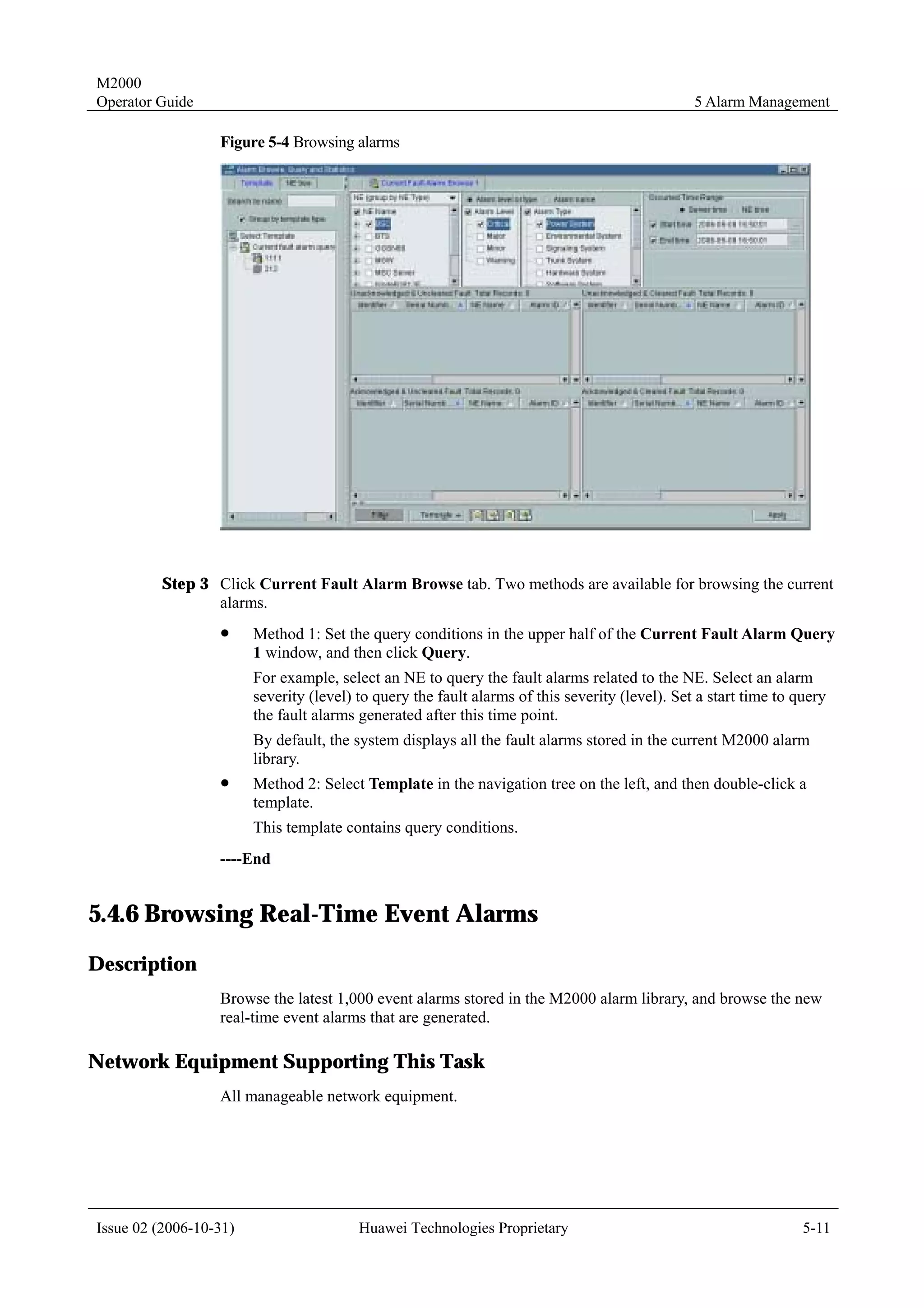
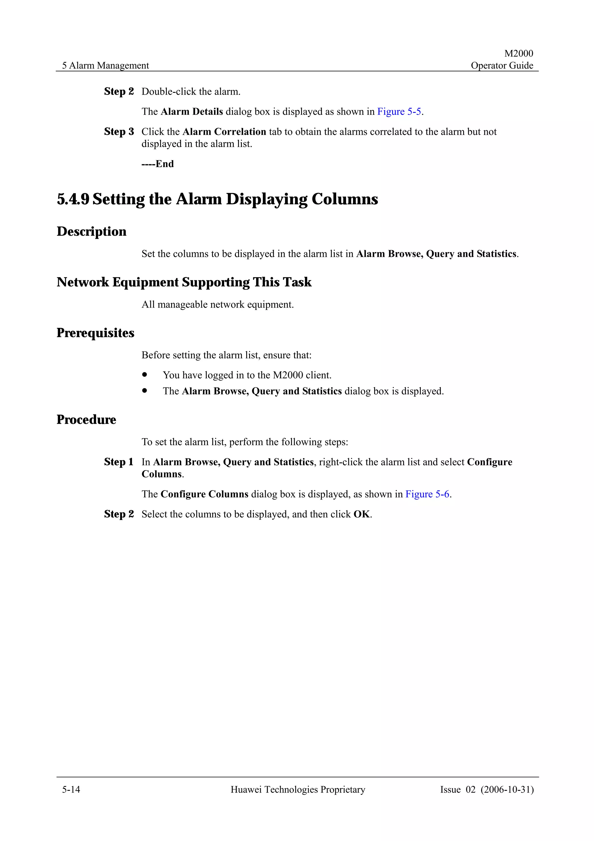
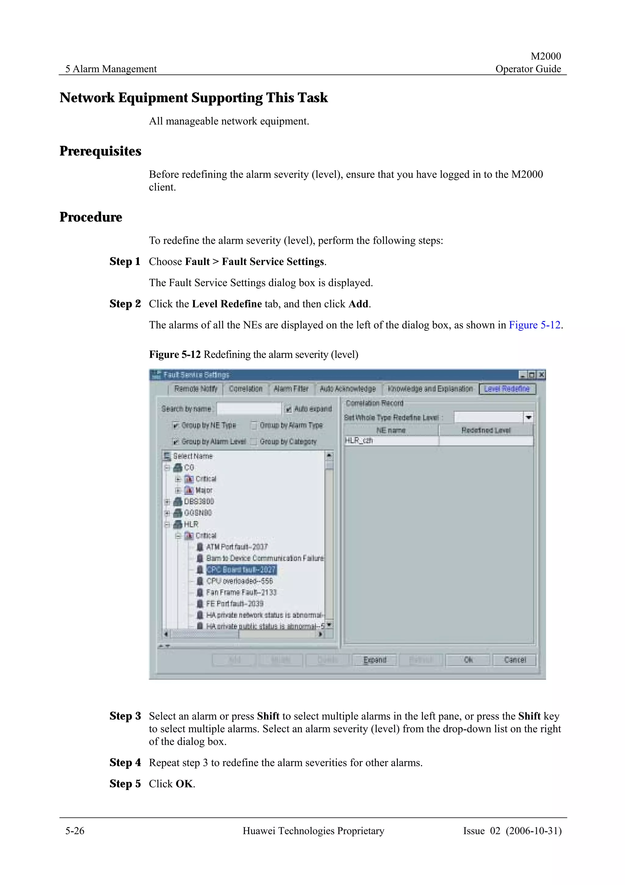
Figure 4-1 An example of CSV templates
Templates in the INI Format
The templates in the INI format apply to create all types of NEs in batches except virtual NEs.
Use the notepad to edit the templates in the INI format. Different from the CSV templates, the
INI templates apply different parameter groups. To create multiple NEs of the same class, the
corresponding parameter groups should be provided accordingly.
The following examples show the parameter groups for some typical NEs.
Example 1: RNC
[RNC]
Name =
Vendor =
Physical Location =
District =
IP address =
Description =
Pos X =
Pos Y =
Position =
Coordination =
Issue 02 (2006-10-31) Huawei Technologies Proprietary 4-5](https://image.slidesharecdn.com/47396377-m2000-operation-guide-121001112620-phpapp01/75/47396377-m2000-operation-guide-29-2048.jpg)
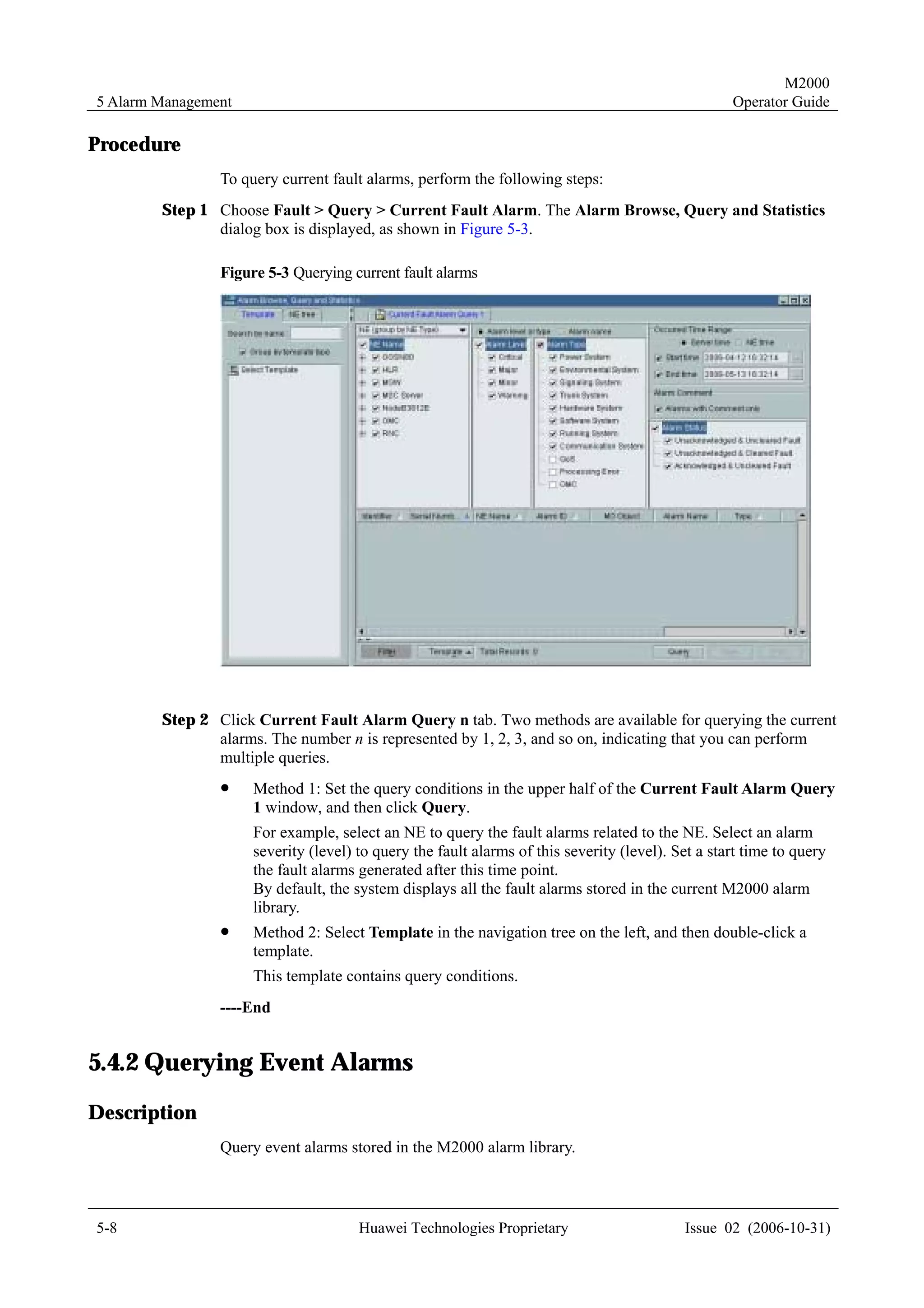
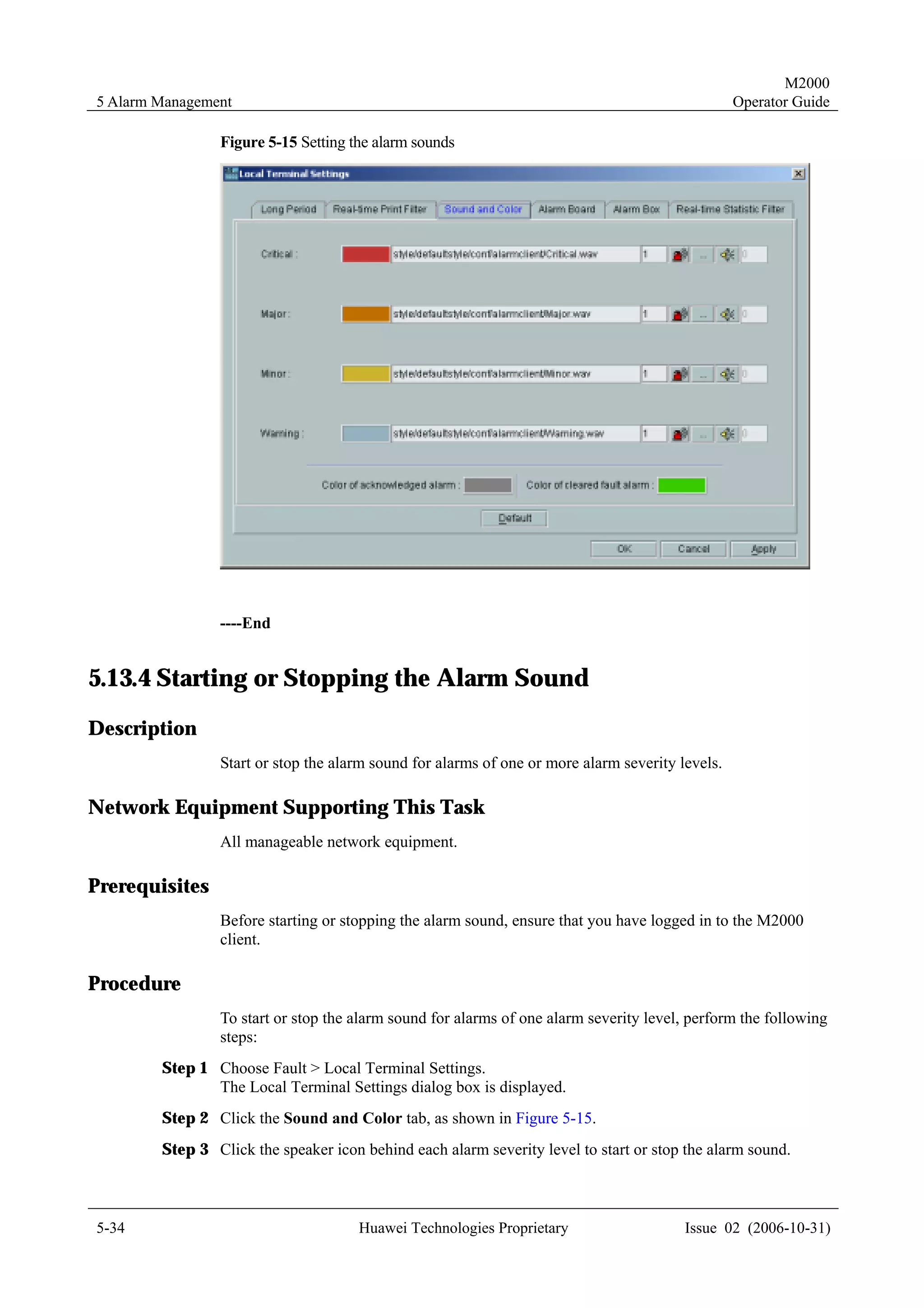
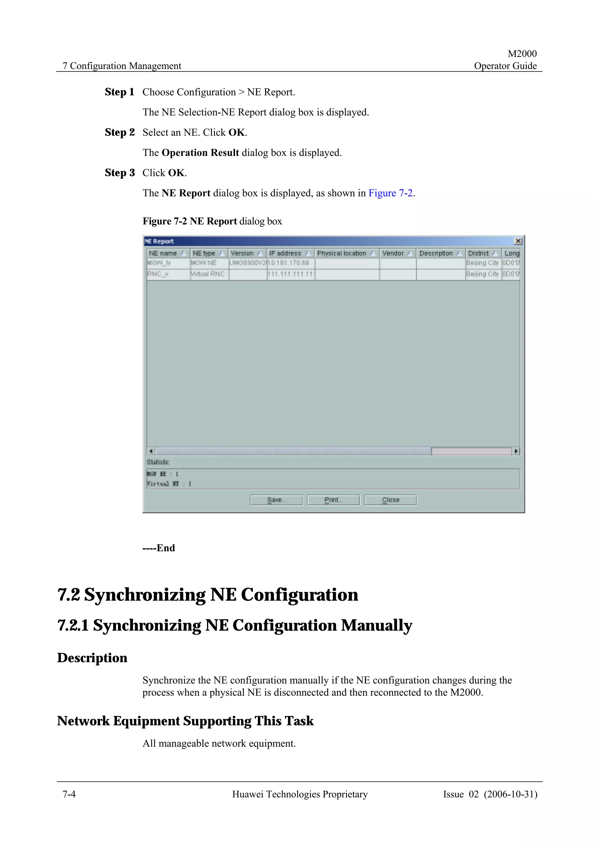
![M2000
4 Topology Management Operator Guide
Example 2: BSC
[BSC]
Name =
Vendor =
Physical Location =
District =
IP address =
Description =
Username =
Password =
Pos X =
Pos Y =
Position =
Coordination =
For the parameters of the INI templates, see M2000 Online Help.
4.2 Creating NEs
4.2.1 Creating Physical NEs
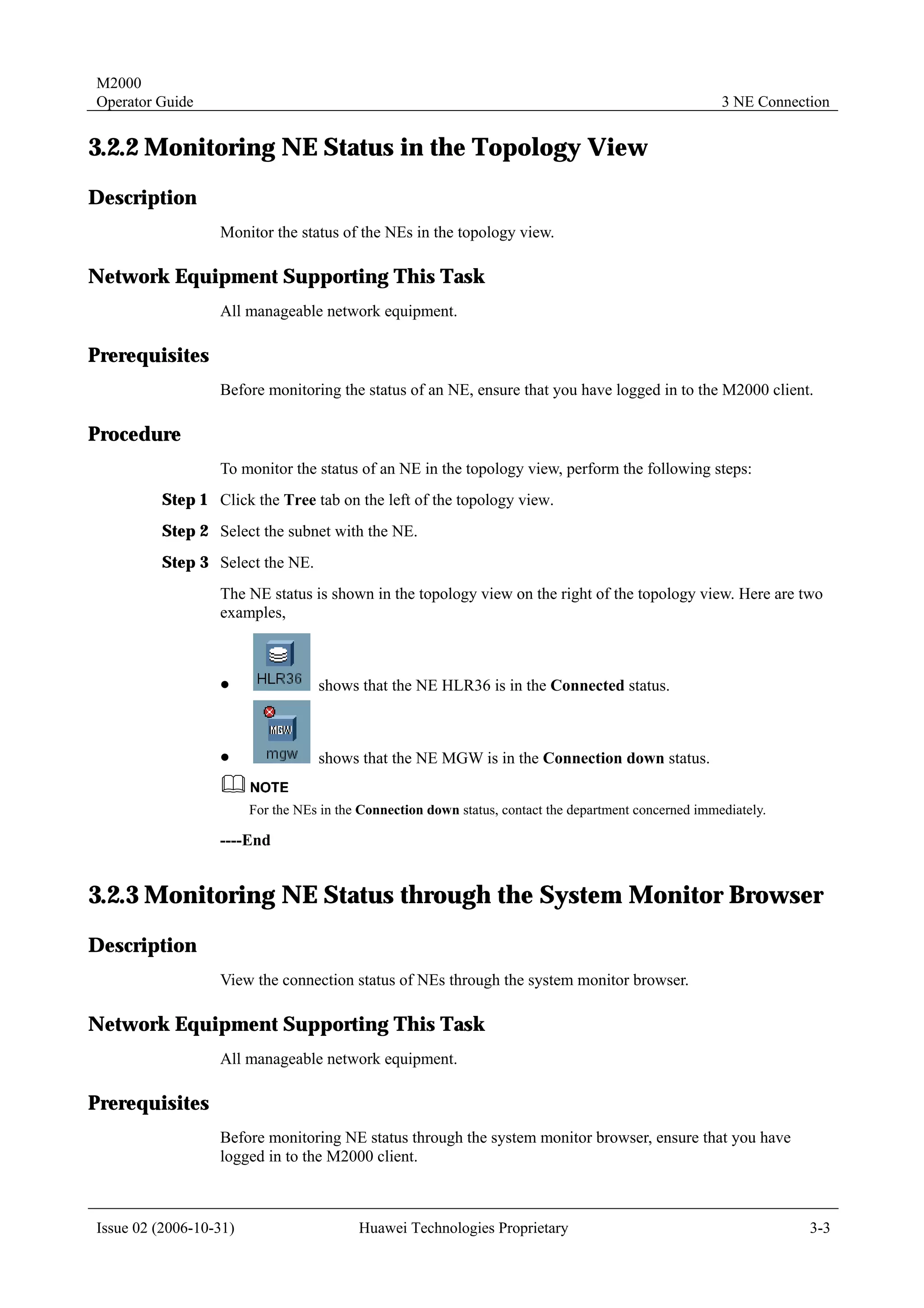
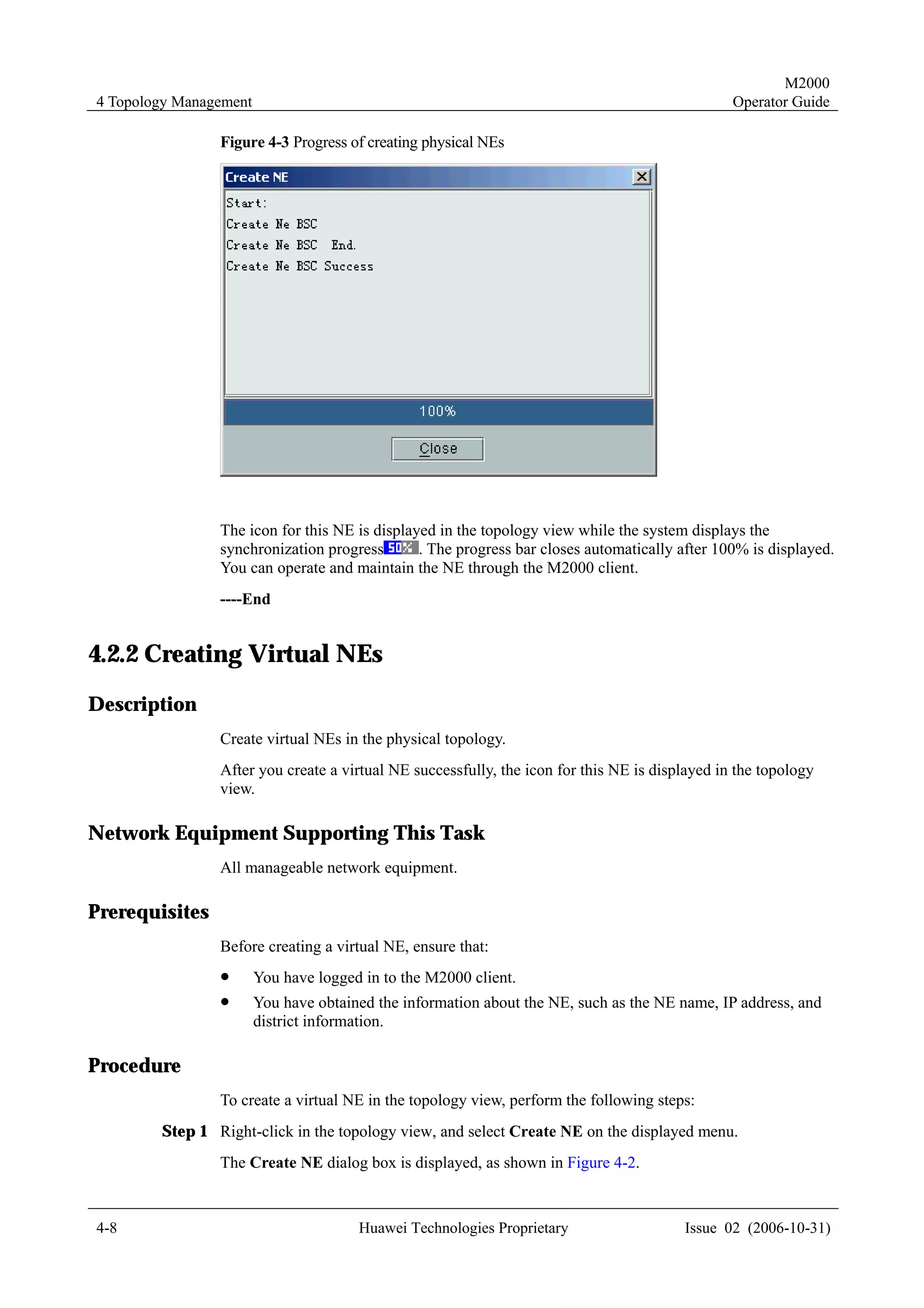
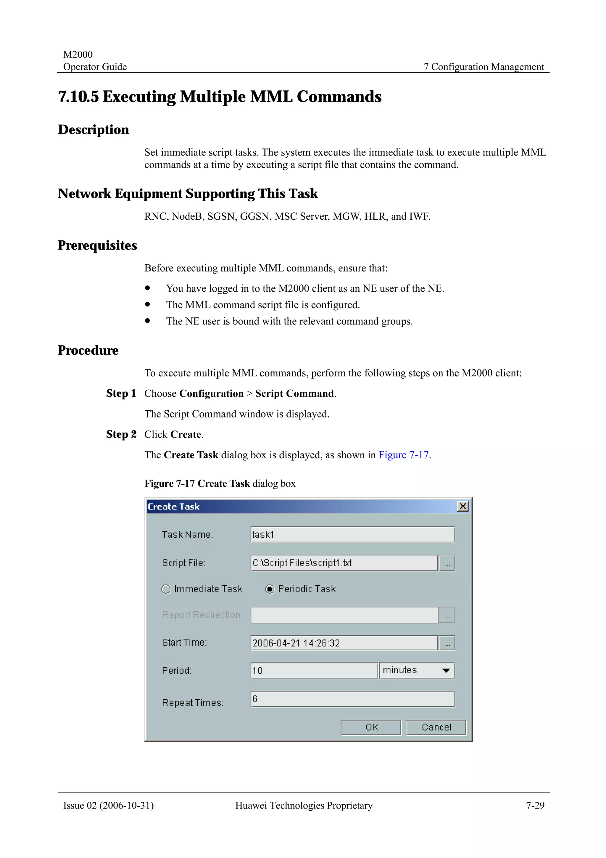
Description
Create physical NEs in the topology view.
After you create an NE successfully, the M2000 synchronizes the NE to obtain the NE
configuration data.
Network Equipment Supporting This Task
All manageable network equipment.
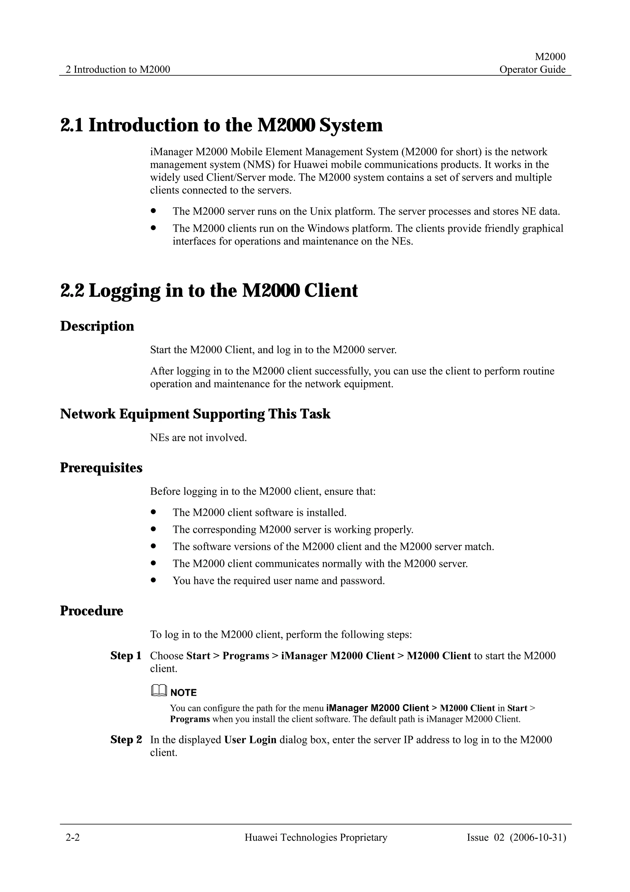
Prerequisites
Before creating a physical NE, ensure that:
! You have logged in to the M2000 client.
! The mediation software for the NE to be created is installed.
! You have obtained the NE information, such as the NE name, IP address, NE version,
and district information.
Procedure
To create a physical NE in the topology view, perform the following steps:
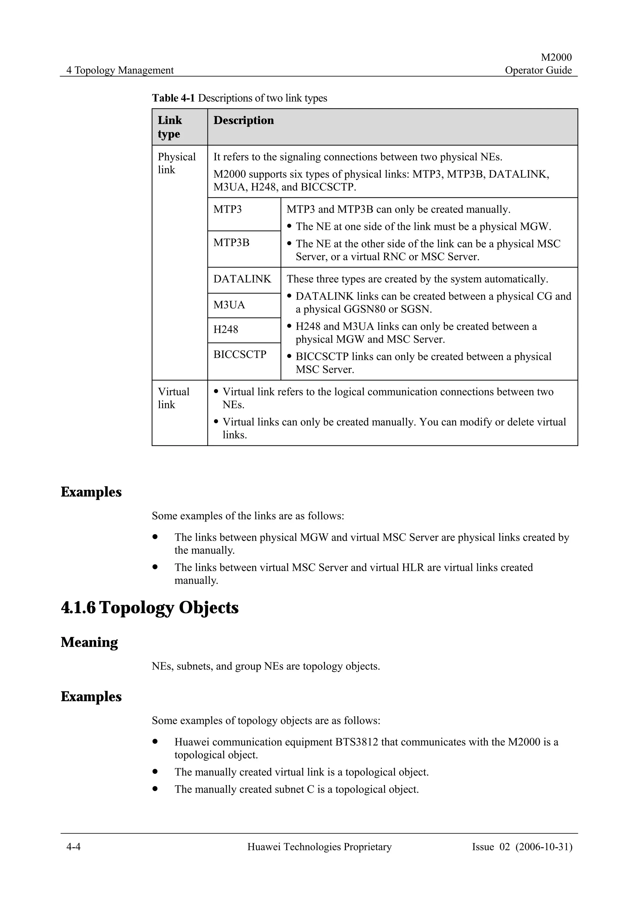
Step 1 Right-click in the topology view, and select Create NE on the displayed menu.
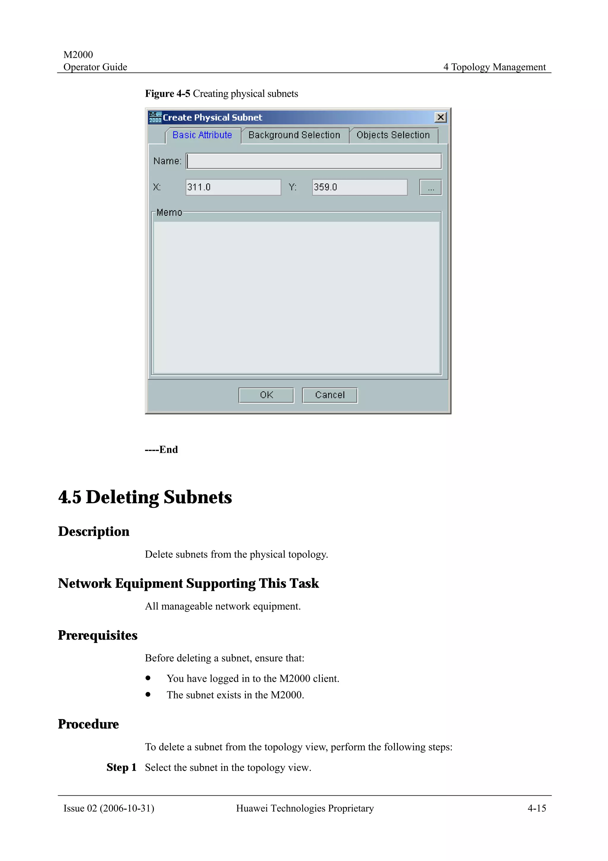
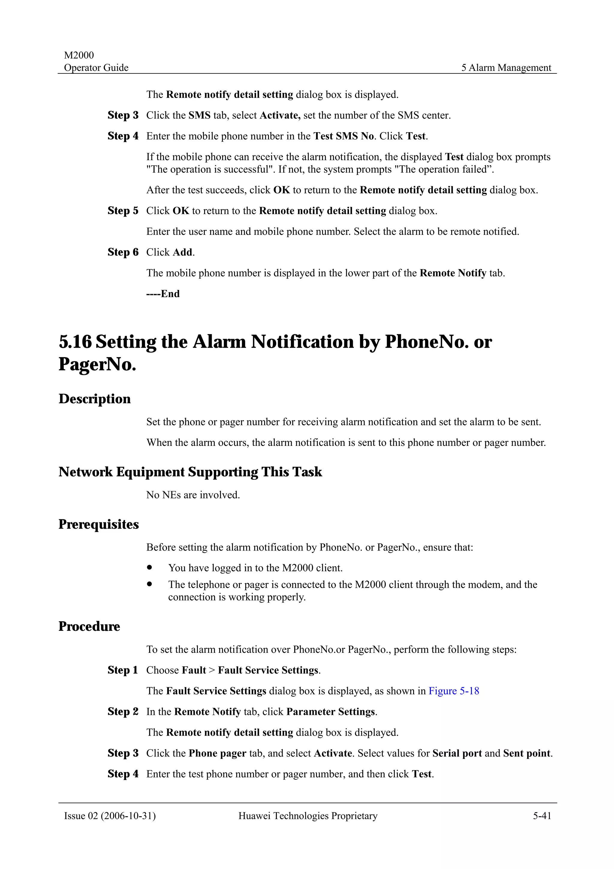
The Create NE dialog box is displayed, as shown in Figure 4-2.
4-6 Huawei Technologies Proprietary Issue 02 (2006-10-31)](https://image.slidesharecdn.com/47396377-m2000-operation-guide-121001112620-phpapp01/75/47396377-m2000-operation-guide-30-2048.jpg)


![M2000
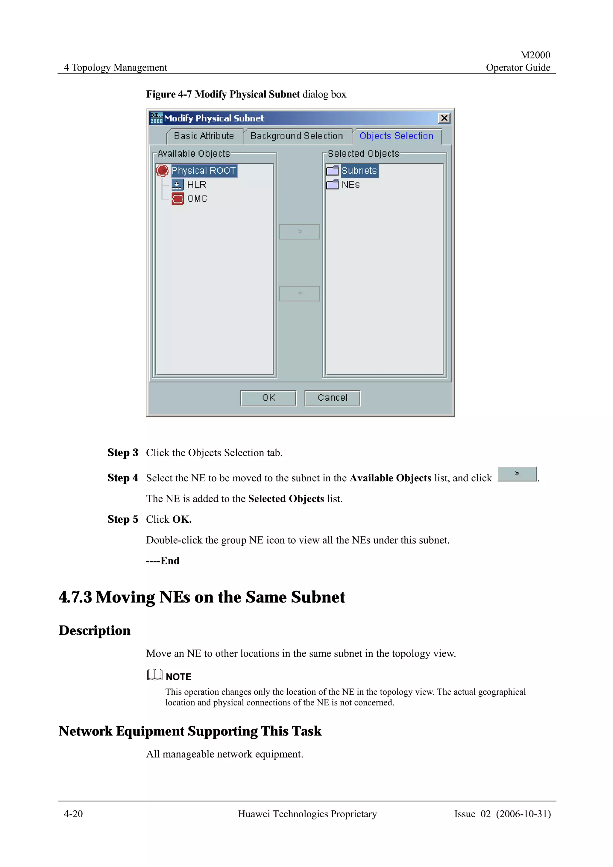
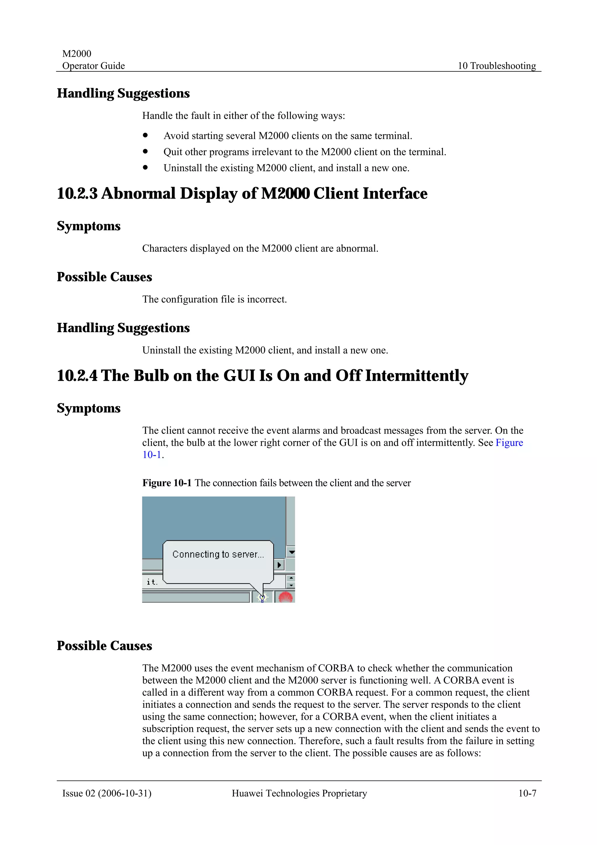
Operator Guide 10 Troubleshooting
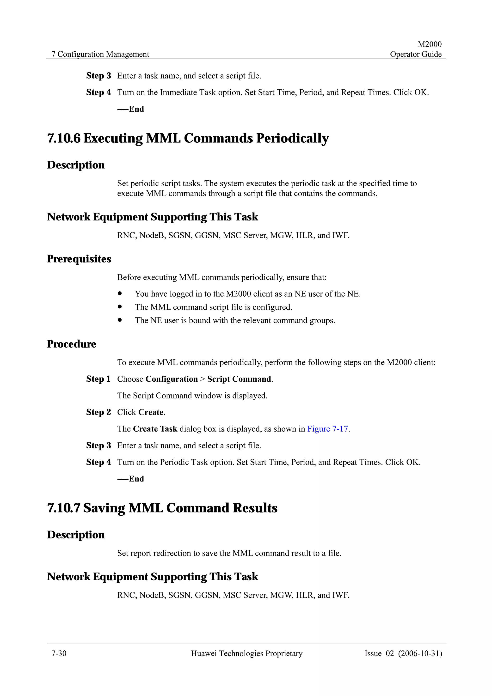
10.3.2 Failure to Discover NodeBs Automatically
Symptoms
The system fails to discover NodeBs automatically.
Possible Causes
The names of the NodeBs are invalid. The NodeB name must not contain the following
characters: ~!, @, #, $, %, ^, &, *, (, ), +, -, =, {, }, [, ], , , |, ;, ', :, , ", <, >, ., ?, /, . Also the
name must not end with a space.
Handling Suggestions
Execute the corresponding commands on the RNC to reset the names of the NodeBs.
10.3.3 Conflicted Names for the Created Topology Objects
Symptoms
When you create a topology object, the system prompts "The attribute value name already
exists." , but you cannot see the topology object with this name in the topology view.
Possible Causes
The causes include:
! The current topology is not refreshed in real time.
! You do not have the privilege to create objects with the same name.
Handling Suggestions
Change the object name and recreate the topology object.
10.4 Alarm Management Faults
10.4.1 Time Delay of Alarm Message Real-Time Printing
Symptoms
After you enable the alarm messages real-time print function, the printer cannot print the
reported alarm messages displayed in the browse window.
Possible Causes
The printer prints the alarm messages when the records fill one whole page or five minutes
after the printer receives the alarms.
Issue 02 (2006-10-31) Huawei Technologies Proprietary 10-9](https://image.slidesharecdn.com/47396377-m2000-operation-guide-121001112620-phpapp01/75/47396377-m2000-operation-guide-210-2048.jpg)