Download to read offline
![Shashank Shekhar Sahoo et al. Int. Journal of Engineering Research and Applications ww.ijera.com
ISSN: 2248-9622, Vol. 6, Issue 3, (Part - 1) March 2016, pp.74-79
www.ijera.com 74|P a g e
Research on Optimization, Dynamics and Stability of Stair-
climbing Wheelchair
Shashank Shekhar Sahoo*, Himank Kinkar**
*(Department of Powertrain, Magneti Marelli India Pvt. Ltd., Gurgaon-51
** (Department of Powertrain, Magneti Marelli India Pvt. Ltd., Gurgaon-51
ABSTRACT
Since the invention of the wheel, man has always sought to reduce effort to get things done easily. Ultimately, it
has resulted in the invention of the Robot, an Engineering Marvel. Up until now, the major factor that hampers
widespread usage of robots is locomotion and maneuverability. They are not fit enough to conform even to the
most commonplace terrain such as stairs. To overcome this, we are proposing a stair climbing wheelchair robot
that looks a lot like a normal wheelchair but with additional stair-climbing functionality to adjust itself
according to the height of the step The primarily goal of the prescribed manuscript herewith is to analyze the
functional requirements, optimization methods, dynamics and stability during a tracked robotic wheelchair’s
climbing of stairs mechanism. At first, the mechanical structure of the wheelchair is designed and the hardware
composition of its full control system is devised. Secondly, based on the analysis of its stairs‐climbing process,
the dynamical model of stairs‐climbing is established by using the classical mechanics method. Next, through
simulation and experiments, the effectiveness of the dynamical model, its stability evaluation and performance
parameters is verified. Such procedures will help in establishing a strong fundamental foundation steps to design
and develop a standalone semi-autonomous wheelchair that will help and enable a physically challenged person
by leg to climb difficult terrains like staircase and speed-breakers with ease and comfort. This design
encompasses Renesas’s Arduino compatible GR-KAEDE boards, servo motors, high torque DC motors and
various peripheral devices as incorporated in design diagram. We have also extended the application of
wheelchair by integrating collision avoidance mechanism.
Keywords - Robot, Arduino, Climbing Robot, wheelchair, GR-KAEDE boards
I. INTRODUCTION
Modern wheelchairs are available with various
accessories, such as anti-tip bars or wheels, safety
belts, adjustable backrests, tilt and/or recline
features, extra support for limbs or neck, mounts or
carrying devices for crutches, walkers or oxygen
tanks, drink holders, and clothing protectors [1].
Transport wheelchairs are usually light, folding
chairs with four small wheels. These allow for a
broader spectrum of movement. However, very few
have experimented to enable a wheelchair with
stair-climbing maneuverability.
During stairs-climbing, the wheelchair begins by
touching the first step of the stairs through its front
track while its two-sided driving motors
simultaneously push the driving wheels and the
whole wheelchair forward, up to the first step and
then the second step, whereby the entire robot
leaves the ground and completely climbs upwards
on the stairs. The whole process may be divided
into six stages, as shown in Figure 1: a) touch the
first step; b) climb up the first step; c) touch the
second step; d) climb up the second step; e) leave
the ground and then ascend the stairs; (f) leave the
stairs and then access the ground. Here, touching
the step means the track near the robot’s front
approach angle climbing onto the step, while
climbing up the step means the bottom track of the
robot climbing onto the step [2].
Fig. 1
RESEARCH ARTICLE OPEN ACCESS](https://image.slidesharecdn.com/m6301074079-160728061528/75/Research-on-Optimization-Dynamics-and-Stability-of-Stairclimbing-Wheelchair-1-2048.jpg)
![Shashank Shekhar Sahoo et al. Int. Journal of Engineering Research and Applications ww.ijera.com
ISSN: 2248-9622, Vol. 6, Issue 3, (Part - 1) March 2016, pp.74-79
www.ijera.com 76|P a g e
pulses (50 in one second) is required to be passed
to the servo to sustain a particular angular position.
When the servo receives a pulse, it can retain the
corresponding angular position for next 20ms, So, a
pulse in every 20ms time frame must be fed to the
servo.
1.2.4 3-AXIS LINEAR ACCELEROMETER
It will closely monitor the tilt of sitting platform
with respect to ground and will assist in
maintaining a perfect horizontal level as required to
keep the integrity of comfort and stability. The
ADXL335 is a small, thin, low power, complete 3-
axis accelerometer with signal conditioned voltage
outputs. The product measures acceleration with a
minimum full-scale range of ±3 g. It can measure
the static acceleration of gravity in tilt-sensing
applications, as well as dynamic acceleration
resulting from motion, shock, or vibration.
1.2.5 POWER SOURCE
A single 12V rechargeable DC battery to supply
enough current to drive huge inductive loads of
high torque motors and related accessories.
1.2.6 COLLISION AVOIDANCE SENSOR (UV
TRANSCEIVERS)
The sensors will check, detect and inform the
microcontroller about any imminent collision
possible due to any nearby object. The HC-SR04
ultrasonic sensor uses sonar to determine distance
to an object like bats or dolphins do. It offers
excellent non-contact range detection with high
accuracy and stable readings in an easy-to-use
package. From 2cm to 400 cm or 1” to 13 feet. It’s
operation is not affected by sunlight or black
material like Sharp rangefinders are (although
acoustically soft materials like cloth can be difficult
to detect). It comes complete with ultrasonic
transmitter and receiver module.
1.2.7 JOY-STICK
To accept directional instructions from the user.
The 2-Axis Joystick is used to add analog input to
our project. The 2-Axis Joystick contains two
independent potentiometers (one per axis) that can
be used as dual adjustable voltage dividers,
providing 2-Axis analog input in a control stick
form. The modular form-factor allows one to plug
the 2-Axis Joystick directly into a breadboard for
easy prototyping. The 2-Axis Joystick includes
spring auto return to center and a comfortable cup-
type knob which gives the feel of a thumb-stick.
1.2.8 GEARED DC MOTORS
To drive the wheels interlocked with conveyer
belts. These are very high torque powerful motors
with the capability to drive the entire system with
ease and activates upon receiving user input from
joystick.
Other active and passive electronic components
like resistors, LEDs, transistors etc.
II. WORKING PRINCIPLE
The customized wheelchair will take directional
instructions as input from driver and will drive the
wheels accordingly as per processed logic. In the
event of staircase climbing, the driver has to orient
the wheelchair with backside facing the stairs.
Then continue normal traversing until the first step
is covered [2]. In order to maintain stability, the
servo motors will then align the sitting platform
horizontal to ground by rotating through an angle
alpha(α). While undertaking this process, 3 axis-
Accelerometer will continuously monitor the level
change of platform with respect to gravity and will
help in achieving accuracy and stability. With this
configuration, one can climb the further steps with
ease. When the distance to potential colliding
object measured by ultrasonic sensors violate the
threshold preset conditions, an alert will be
displayed on LCD to stop the wheelchair
automatically as per Mode 0 operation and will
wait for next user’s instruction to switch into Mode
1 to continue moving , keeping minimum distance
to detected object in mind.
III. SYSTEM DESIGN SPECIFICATION
3.1 MECHANICAL
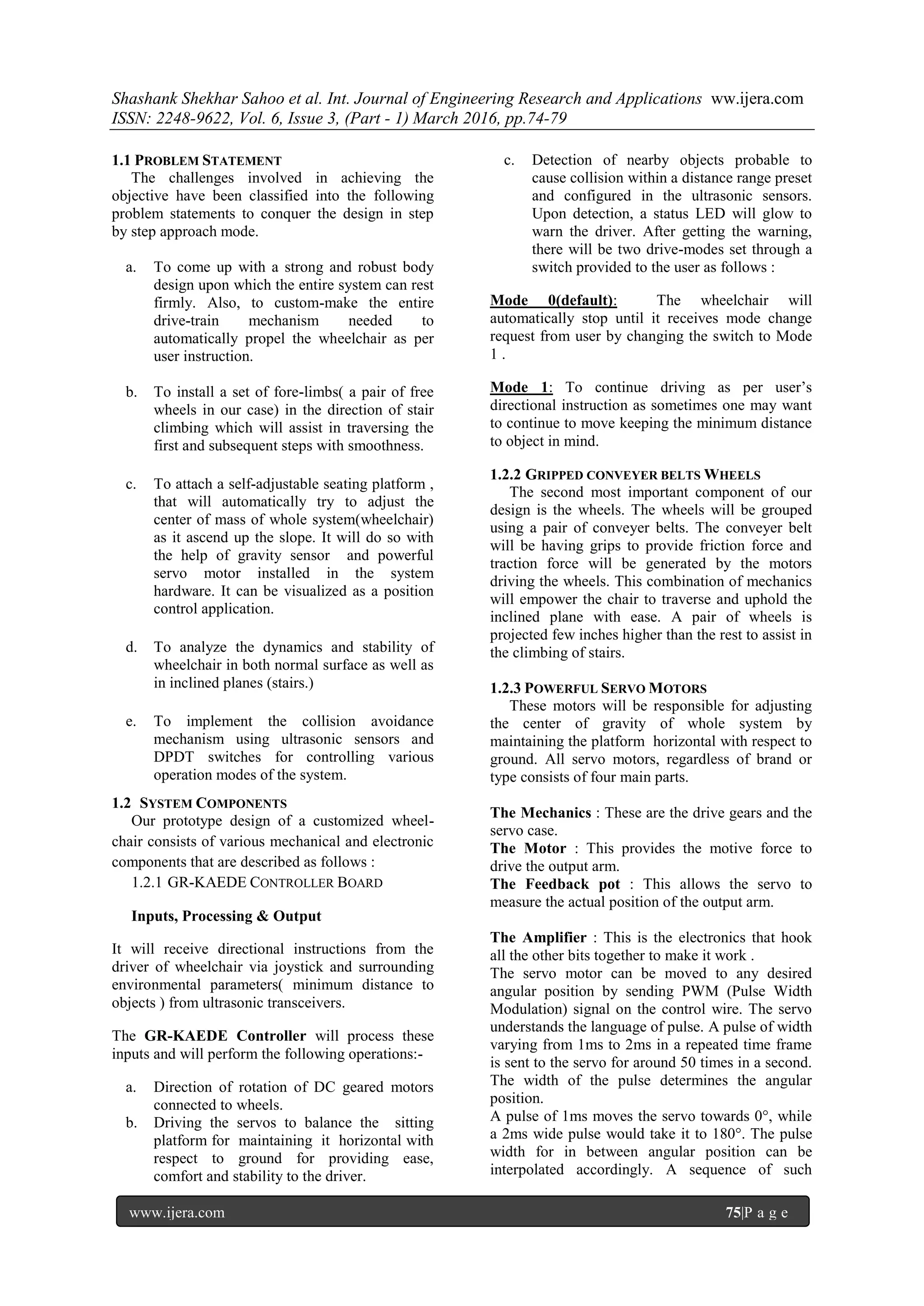
The chassis used in the wheelchair is an in-
house custom-made prototype that involves the
combination of an innovative axles, highly stable
metal body, bi-cycle sprocket with gear sets and
screw joints to fix them all together. The axles used
in the project are actually reverse-engineered
version of what we normally see in bicycle, where
a single pedal turn of larger diameter sprocket
results in multiple turns of smaller diameter
sprocket connected to the rear wheels. Similarly,
here also we have mechanically coupled a pair of
wheels with similar axles and installed gear set on
it which will be propelled by high torque powerful
DC motors using driver and driven mechanism.
The sprocket of front and rear axles are coupled
mechanically using chain- links that are usually
found in bi-cycles, and these are customized and
adjusted to fit the design with zero tension and
torsion force. This mechanism is replicated on
other side as well taking into account the other pair
of wheels. The USP of this particular design is that
just by connecting a single high torque DC motor,
one can propel the entire one-half of the system.
So, technically speaking two motors are sufficient
enough in this design to propel the entire four-
wheel drive system with ease and comfort. Four
such combination consisting of sprocket, axle, axle
with gears and chains are formulated in such a
manner to provide high stability to the system [3].](https://image.slidesharecdn.com/m6301074079-160728061528/75/Research-on-Optimization-Dynamics-and-Stability-of-Stairclimbing-Wheelchair-3-2048.jpg)
![Shashank Shekhar Sahoo et al. Int. Journal of Engineering Research and Applications ww.ijera.com
ISSN: 2248-9622, Vol. 6, Issue 3, (Part - 1) March 2016, pp.74-79
www.ijera.com 78|P a g e
Fig. 5
IV. IMPLEMENTATION NOTE
It started with chassis design which is a
rectangular frame with compartments for wheel and
driving motors. Then the axle design, that has been
customized out of bi-cycle axles. It has been made
retro fit to accommodate gears and sprocket around
the opposite sides of rim. Four such units were
designed with sprockets on all the four and driving
gears on the rear wheels [4].
We needed to add additional pair of wheels to
enable the wheelchair to climb the stairs . For this a
separate pair of wheels were made to project out of
wheelchair body with marginal lift but in alignment
with other wheels. The main usage was to assist the
wheelchair to climb stair steps with ease. The next
step was to wrap around a set of two conveyer belts
encompassing wheels in phase and alignment.
Doing such made the wheel drive more robust and
it ensured proper movement of wheels in difficult
terrains without losing traction and control off the
road or stairs.
Later on, a stable light weight platform was
attached around the horn of the servo and was
mounted with the help of two center mast from the
central section of chassis. This platform is also
connected mechanically to accelerometer to detect
change in orientation of the platform and to make
the platform parallel to the ground.
As add-on in our custom designed wheelchair we
have also attached an ultrasonic sensor in the
façade of system to detect any nearby object which
might cause imminent collision.
During prototype testing it was observed that the
sprocket chain arrangement was creating a hurdle
while climbing the stairs as the radius of the wheels
chosen wasn’t providing sufficient edge clearance.
So, chain was removed.
All these modules were tested within their
constraints and in compliance with their
specification to meet the required objective over
various load conditions.
V. CIRCUIT DIAGRAM
Fig. 6
VI. SYSTEM TESTING, RESULTS &
DISCUSSION
The wheelchair system is developed in
compliance with modular development strategy.
So, it’s testing is also done in somewhat similar
manner. We have performed multiple unit – testing
of various system parts while they are under
development in order to ensure about the quality,
endurance, stability , robustness and integrity.
Some of the tests performed are as follows :-
a. Test to check proper fitting of wheel cut-set
with that of axle.
b. Test to inhibit back free-movement of
sprocket by welding of sprocket inner body
with that of axle.
c. Test to check and ascertain any relative
motion between gear cut-set and axle , that
might result as consequence of loose bond
between the two parties.
d. Test to ensure ground clearance and stability
of entire system while the installation of all
four wheels is done.
e. Test to observe the behavior of system in
terms of traction control, stability, driving
torque and custom manoeuvrability by just
installing the motors but not the conveyer
belts. Technically, we want to make it
traverse an inclined plane simulating the
same angle of inclination as that of stairs.
f. Next test was to fit the chain-links
encompassing both front and back sprocket
with no tension and with perfect ground and
stair clearance.
g. Test to check whether the wheelchair is able
to climb the very first step or not after fitting
the conveyer belts in their place.
For the purpose of proving the results of the
dynamical model and the stability analysis for
stairs-climbing, we perform a simulation
calculation and experiments on the developed
wheelchair robot. The structural parameters of the
robot are: the radius of the driving wheels is
R=250mm; the radius of the steering wheels and
the fixed wheels are both r=140mm; the length of
the bottom tracks is L=600mm; the front approach
angle is α=40°. The robot has two DC servo motors
with 400 watts power and the total mass of the robot
is m=62kg. The frictional factor between the tracks
and the sharp corner of the steps is 0.2.
According to the defined modes of motion, we
make a simulation calculation of the wheelchair’s
stairs-climbing experiments . In Figure 7, the
stability profile of wheelchair during the course of
its manoeuvre are best depicted in the profile
below :-](https://image.slidesharecdn.com/m6301074079-160728061528/75/Research-on-Optimization-Dynamics-and-Stability-of-Stairclimbing-Wheelchair-5-2048.jpg)
![Shashank Shekhar Sahoo et al. Int. Journal of Engineering Research and Applications ww.ijera.com
ISSN: 2248-9622, Vol. 6, Issue 3, (Part - 1) March 2016, pp.74-79
www.ijera.com 79|P a g e
Fig.7
The lowest point of stability during the robot’s
stairs-climbing occurs during those moments when
the driving wheels leave the ground and the
robot’s driving wheels roll over the first and
second steps. The main reason is that the driving
wheels are suddenly suspended in the air. This has
the result that the robot’s rolling fulcrum moves
forward substantially and thus it inclines to
tumble backwards more easily. This conclusion is
also proven in the tracked mobile robot’s stairs-
climbing experiments [5].
VII. CONCLUSION
Given a wheelchair the issue of how to ensure
stability in stairs-climbing is an important problem
which needed to be solved. Looking at this
problem, the dynamical model and the question of
stability during wheelchair’s stairs-climbing are
studied based on a mechanics analysis. The
acquired achievements can provide design and
analysis foundations for the wheelchair’ stairs-
climbing and solve the problem, which can be
summarized as follows:
(1) According to the requirement for stairs-
climbing, the mechanical structure of a
tracked mobile robot is designed and the
hardware composition of its control system is
given.
(2) Based on the analysis of the stairs-climbing
process, the dynamics model of the tracked
mobile robot during stairs-climbing is
established, which can provide fundamental
support for the stability analysis.
Fig. 8
The stability conditions for its stairs-climbing are
obtained. A quantitative evaluation method of the
stairs-climbing stability of the tracked mobile robot
is proposed and verified through simulation and
experiments.
This project will solve the issues faced by
physically challenged person through leg in day to
day life such as climbing staircase and having
additional security by averting collisions. This
project can be further extended to incorporate
feature like android application or wireless
technology based emergency message alert and
providing directional input to wheelchairs via icons
displayed in the smartphone screen. The emergency
notification will inform the relatives
instantaneously, thus providing safety and security
to the rider. This design can be used to carry heavy
objects in multistory buildings and military
surveillance purposes. It has the potential to play
active role in disaster management situations also.
References
[1] Hebert M H, Thorpe C E, Stentz A (1997)
Intelligent Unmanned Ground Vehicles.
Boston: Kluwer Academic Press. p. 310.
[2] Figliolini, G., and Ceccarelli, M. (2001).
Climbing stairs with EP-WAR2 biped
robot. IEEE International Conference on
Robotics and Automation, Seoul Korea, 4
4116-4121.
[3] Ben.Tzvi P, Ito S, Goldenberg A A (2007)
Autonomous Stair Climbing with
Reconfigurable Tracked Mobile Robot.
IEEE International Workshop on Robotic
and Sensors Environments, Ottawa,
Canada. pp. 16.
[4] Davids A (2002) Urban Search and
Rescue Robots: From Tragedy to
Technology. Intelligent System of IEEE.
17(2): 81-83.
[5] Birk A, Carpin S (2001) Rescue Robotics
a Crucial Milestone on the Road to
Autonomous Systems.Advanced Robotics
Journal. 20(5): 595-576.](https://image.slidesharecdn.com/m6301074079-160728061528/75/Research-on-Optimization-Dynamics-and-Stability-of-Stairclimbing-Wheelchair-6-2048.jpg)

The document describes a proposed design for a stair-climbing wheelchair. It includes mechanical components like a custom chassis, axles connected to wheels via sprockets and gears to be powered by DC motors. Electrical components include motor drivers and sensors like an accelerometer and ultrasonic sensors. The wheelchair is controlled by a microcontroller board that processes inputs from a joystick and sensors. It controls motors and servos to enable climbing stairs and maintain stability. The design aims to allow physically challenged users to navigate difficult terrains like stairs with ease and safety.


![iotoperatedwheelchair8thsem-170425052323_(1)[1] - Copy.pptx - AutoRecovered...](https://cdn.slidesharecdn.com/ss_thumbnails/iotoperatedwheelchair8thsem-17042505232311-copy-251101122002-e1587880-thumbnail.jpg?width=640&height=640&fit=bounds)
![iotoperatedwheelchair8thsem-170425052323_(1)[1] - Copy.pptx](https://cdn.slidesharecdn.com/ss_thumbnails/iotoperatedwheelchair8thsem-17042505232311-copy-251101122238-dd3b998f-thumbnail.jpg?width=640&height=640&fit=bounds)


