This document provides a design for the network of DIT Bank, a medium-sized banking organization. It includes:
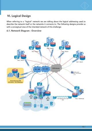
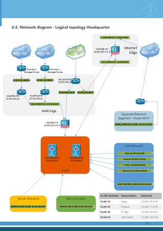
1) Logical and physical network diagrams for the headquarters building and remote locations. Subnets are defined for different departments and sites.
2) Requirements for the network design including business goals of reducing costs and enhancing productivity, and technical goals of high availability, scalability, and security.
3) Descriptions of the network applications used by banks and the different user communities and data stores.
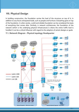
4) Details of the physical network infrastructure for the headquarters and remote sites, including access, distribution, and core networks at HQ and connectivity between sites.
![Formal Element - Network Design
Challenge
NETW3205 Network Management
DT080A/3C
Report: Ricardo Pereira [C13762541]
Lecturer: Noel McKenna](https://image.slidesharecdn.com/231f103e-1063-4085-ac6c-ba35498ea377-160704153315/85/REP-01-NETW3205-Network-Management-1-320.jpg)

![III. Project Scope
/6
Project Scope The following is within scope for the project:
The scope for the implementation of the DIT Bank Network will
include all planning, design, selection, and decisions for building a
new IT infrastructure;
• Project management (planning and budgeting)
• System strategy for all applications and infrastructure
• Application management
• Moving day execution
• Acceptance testing
• Project wrap up
The following is out of scope for the project:
Out of scope for this project is the build, renovation, or co-
location of the new data center [this DC will be off country but this
report won’t provide details on this infrastructure, except to
define that it will be a Tier 4 DC].
Out of scope for this project is the cost for the ISP MPLS access,
due to the fact that the contacted providers did not reply to the
queries.
Background (optional) Network Scenario:
A new medium sized banking organisation called DIT Bank with
approx. 500 employees spread across various sites and countries
is being created as a result of a joint venture.](https://image.slidesharecdn.com/231f103e-1063-4085-ac6c-ba35498ea377-160704153315/85/REP-01-NETW3205-Network-Management-6-320.jpg)
![5.3. User Communities and Data Stores
A user community is a set of workers who use a particular application or set of applications. A
user community can be a corporate department or set of departments; in this scenario, the
user community will be the bank sharing hardware and software information across the sites.
A data store is an area in a network where application layer data resides. A data store can be
a server, a server farm, a storage area network (SAN), a mainframe, a tape back-up unit, a
digital village library, or any device or component of an internetwork where large quantity of
data are stored i.e. the bank will have a DNS server installed at HQ for managing of internet
domains.
5.4. Network Applications
Banks and financial institutions can benefit from a full array of services, from IT strategy
development and the deployment of application systems, to the creation of corporate-level
information infrastructures.
• Banking Automation System
• CRM Systems:
• Oracle Siebel CRM
• SAP CRM
• Data Analysis and Storage Systems:
• Oracle Financial Services Applications
• Oracle Mantas Anti Money Laundering
• Oracle Reveleus Risk Management
• Oracle Enterprise Performance Management (Oracle Hyperion product line)
• Oracle Business Intelligence
• SAP SEM, BW, BI
• Bank Reporting Systems
• Integrated Solutions and Customised Projects (including systems based on):
• Oracle BPEL Process Manager
• Oracle Enterprise Service Bus
• Oracle Data Integrator
• E-mail
• Instant messaging
• Remote login
• VoIP[Softphones]
• Real-time video conference
/9](https://image.slidesharecdn.com/231f103e-1063-4085-ac6c-ba35498ea377-160704153315/85/REP-01-NETW3205-Network-Management-9-320.jpg)
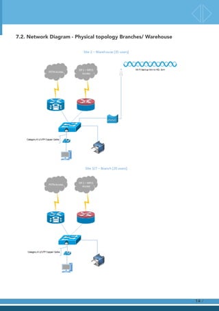
![7.3.1 Solution Description Warehouse and Branches
Site #2 - Warehouse
The warehouse is located in a separate location, about 1km away from Office#1 block. Used
for “credit/debit card” manufacturing. PCs for inventory and tracking are used. (35 users
planned). This is a small network and stands on top of a category 6 infrastructure allowing the
desktop users to be connected at 1GB links by the Cisco Catalyst 3650 Series 48
10/100/1000 switch. The network is connected to the headquarter by two cisco
routers[voice/ data] and backup is established via Wi-Fi connection using a Cisco Aironet
1300 Series Outdoor Access Point/Bridge.
Figure 7: Network Diagram with Power Injector
Site #3/7 - Branches
The branches are spread across different geographical regions and connect the network
stands on top of a category 6 infrastructure allowing the desktop users to be connected at
1GB links by the Cisco Catalyst 3650 Series 48 10/100/1000 switch. The network is connected
to the headquarter by two cisco routers[voice/ data] with VPN IPSec-based branch office
WAN links. The choice for IPSec is for the fact that IPSec VPNs protect IP packets exchanged
between remote networks or hosts and an IPSec gateway located at the edge of your private
network while SSL VPN products protect application streams from remote users to an SSL
gateway. In other words, IPSec connects hosts to entire private networks, while SSL VPNs
connect users to services and applications inside those networks.
/16](https://image.slidesharecdn.com/231f103e-1063-4085-ac6c-ba35498ea377-160704153315/85/REP-01-NETW3205-Network-Management-16-320.jpg)
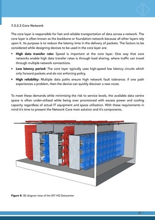
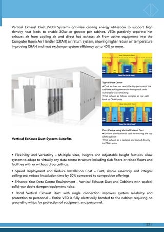
![IT Managers, challenged to maximise the utilisation of available rack-space and cooling
capacity, often increase the power density per cabinet.
As cabinet power densities rise, containment architectures are the optimal approach,
ensuring uniform cooling air temperature is delivered to equipment in high density PODs
allowing full utilisation of available cabinet space and cooling capacity.
/22
Vertical Exhaust Duct [VED]
Overhead Cable Pathway Systems
Sealing
Accessories
Server type
Cabinets
Hardware monitoring systemNetwork type Cabinets with
angular patch panels](https://image.slidesharecdn.com/231f103e-1063-4085-ac6c-ba35498ea377-160704153315/85/REP-01-NETW3205-Network-Management-22-320.jpg)
![IX. Implementation Plan
The following implementation plan contains the work breakdown structure [WBS] for the DIT
Bank network.
9.1. Project Schedule
/31](https://image.slidesharecdn.com/231f103e-1063-4085-ac6c-ba35498ea377-160704153315/85/REP-01-NETW3205-Network-Management-31-320.jpg)
![References
Apc.com. (2016). InRow Direct Expansion|APC. [online] Available at: http://www.apc.com/shop/zm/en/categories/
cooling/close-coupled-air-conditioners/inrow-direct-expansion/_/N-1wpqwmc# [Accessed 28 Apr. 2016].
Apc.com. (2016). Symmetra PX|APC. [online] Available at: http://www.apc.com/shop/zm/en/categories/power/ups/
data-center-and-facility-3-phase/symmetra-px/_/N-1sk02b8# [Accessed 28 Apr. 2016].
Cisco. (2016). Cisco ASA 5500-X Series Firewalls - Products & Services. [online] Available at: http://
www.cisco.com/c/en/us/products/security/asa-5500-series-next-generation-firewalls/index.html [Accessed 28
Apr. 2016].
Mcmcse.com. (2016). Cisco Tutorial: The Cisco Three-Layered Hierarchical Model. [online] Available at: http://
www.mcmcse.com/cisco/guides/hierarchical_model.shtml [Accessed 28 Apr. 2016].
Panduit.com. (2016). Copper Cabling and Connectivity Systems. [online] Available at: http://www.panduit.com/wcs/
Satellite?c=Page&childpagename=Panduit_Global/
PG_Layout&cid=1345564328987&packedargs=classification_id=1949724&locale=en_us&pagename=PG_Wr
apper [Accessed 28 Apr. 2016].
Panduit.com. (2016). Fiber Cabling and Connectivity Systems. [online] Available at: http://www.panduit.com/wcs/
Satellite?c=Page&childpagename=Panduit_Global/
PG_Layout&cid=1345564329011&packedargs=classification_id=1978676&locale=en_us&pagename=PG_Wr
apper [Accessed 28 Apr. 2016].
Services, P. (2016). Security - Products & Solutions. [online] Cisco. Available at: http://www.cisco.com/c/en/us/
products/security/product-listing.html#Firewalls [Accessed 28 Apr. 2016].
Services, P., Routers, C., Literature, D. and Sheets, D. (2016). Cisco 4000 Series Integrated Services Router
Family Ordering Guide. [online] Cisco. Available at: http://www.cisco.com/c/en/us/products/collateral/routers/
4000-series-integrated-services-routers-isr/guide-c07-732797.html [Accessed 28 Apr. 2016].
/32](https://image.slidesharecdn.com/231f103e-1063-4085-ac6c-ba35498ea377-160704153315/85/REP-01-NETW3205-Network-Management-32-320.jpg)