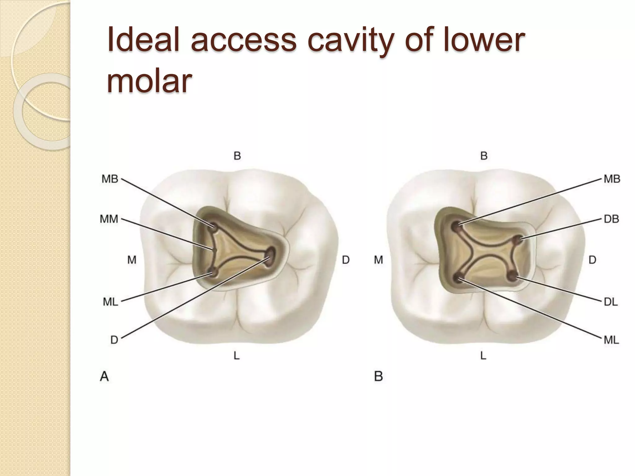
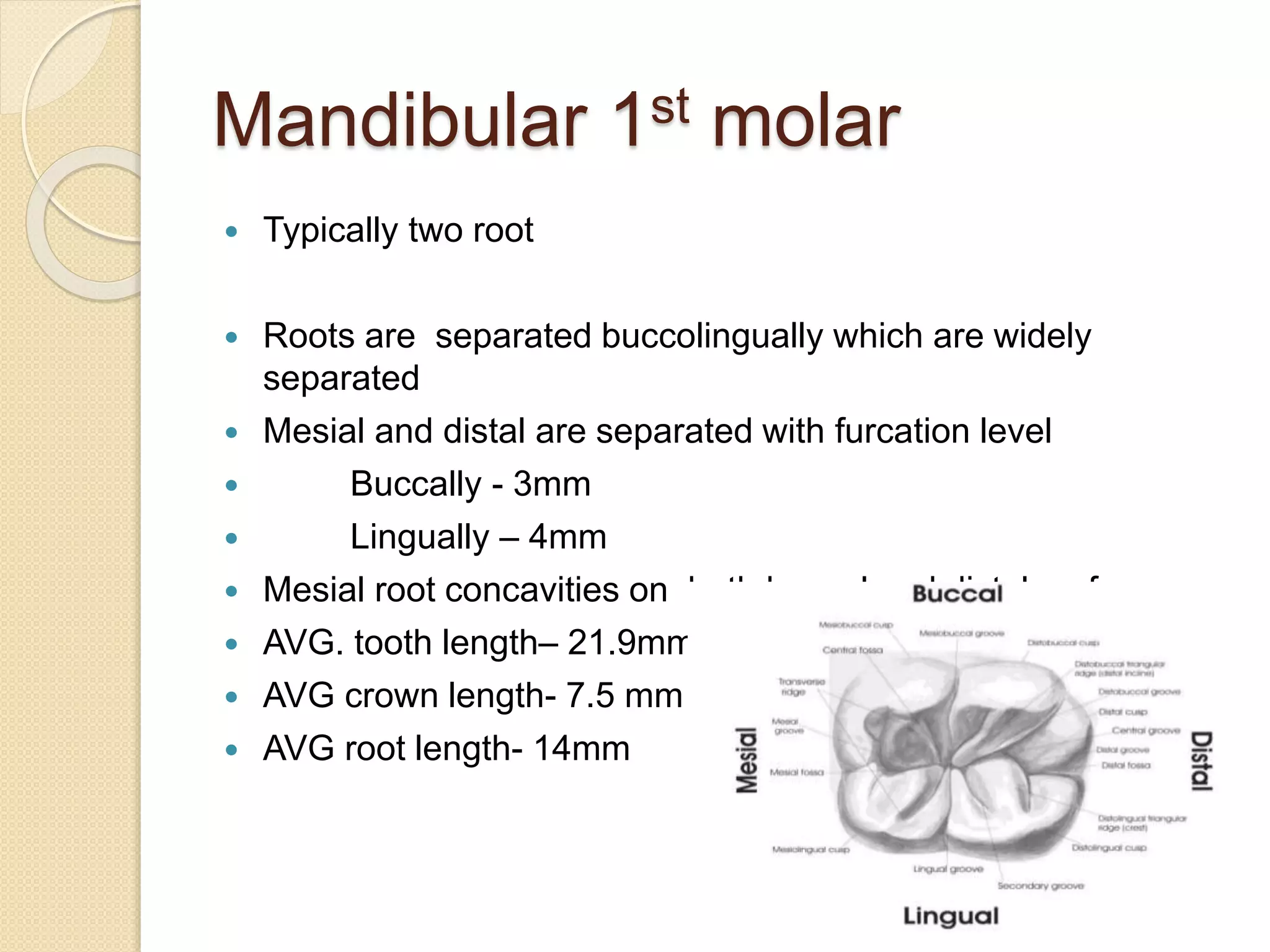
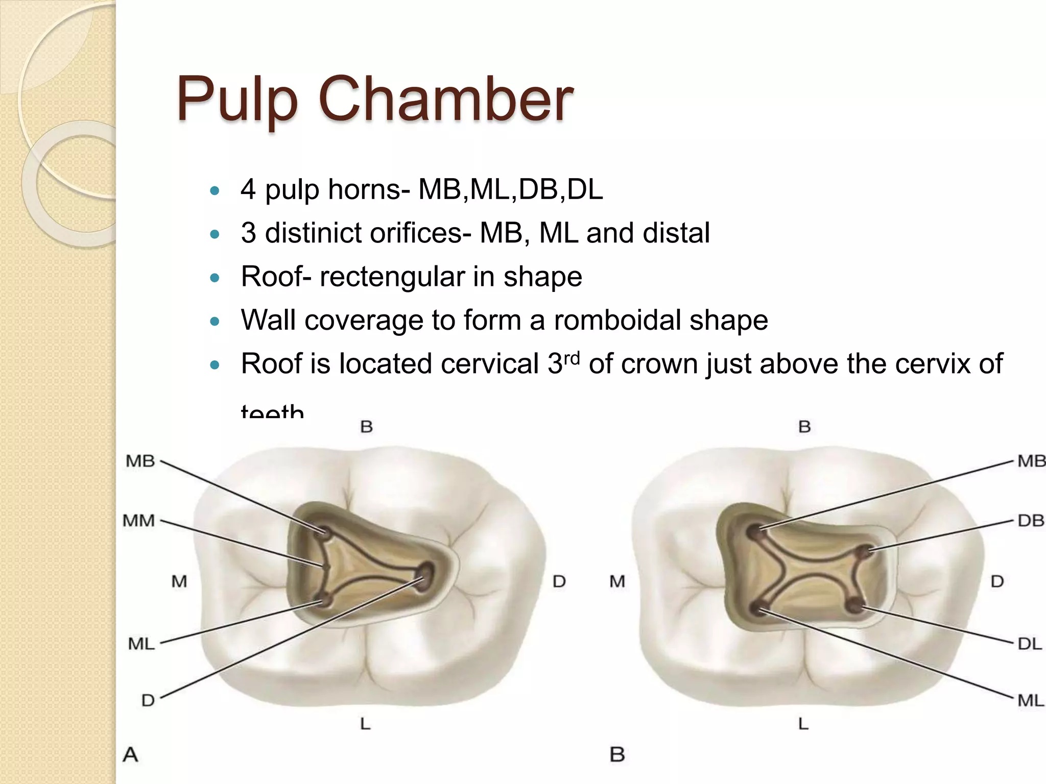
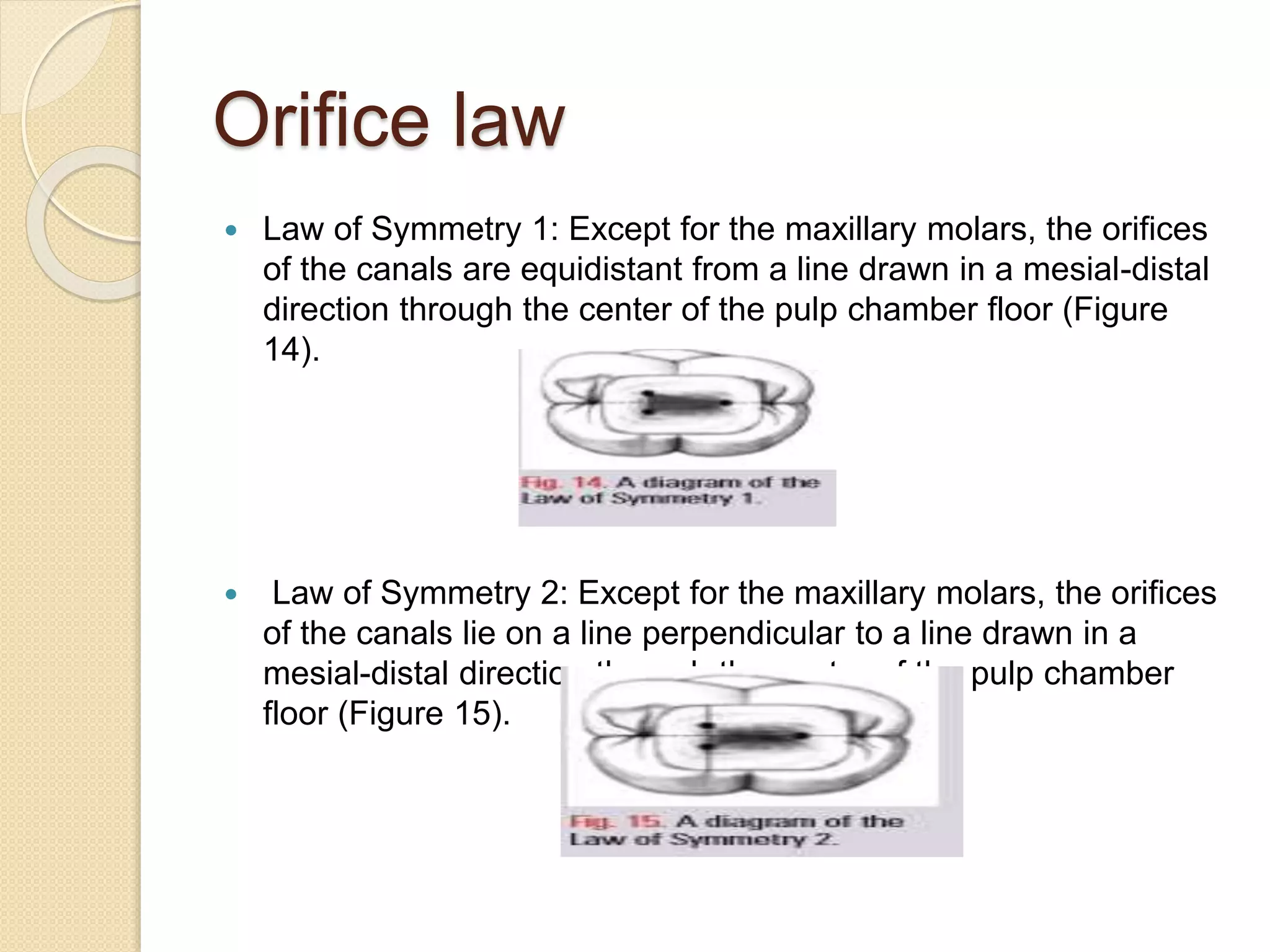
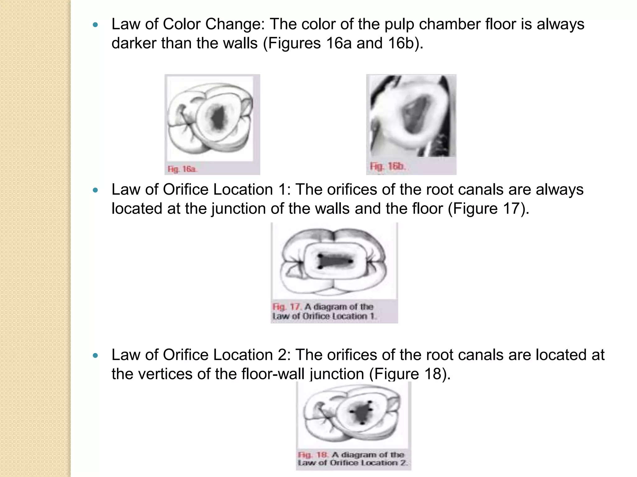
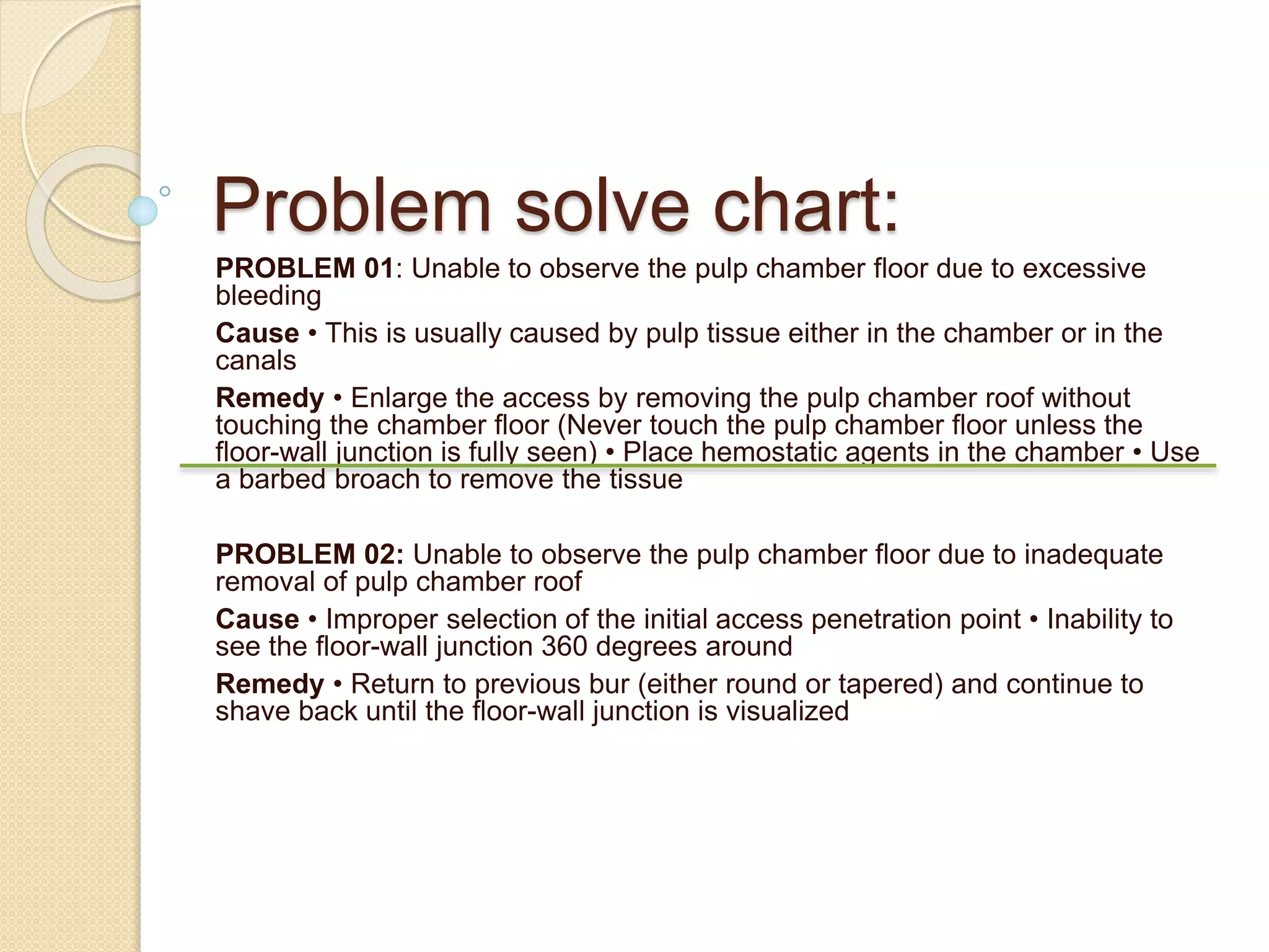
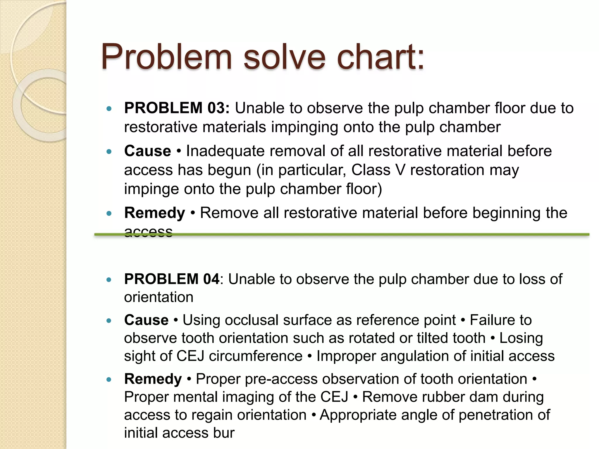
Relation Of access cavity design to
the canal orifice of lower 1st molar
Access cavity preparation:
A coronal opening to the centre of a
tooth required for effective
cleaning,shaping,opturation of the
pulp canals and chamber during
endodontic or root canal therapy.
Objective:
 Well designed access preparation is essential for a
good endodontics result.without adequate
access,instuments and material becomes difficult to
handle properly in the highly complex and variable
canal system.
 To achive a straight or direct line access to the apical
foramen
 To locate all root canal orifice
 To conserve sound tooth structure
 Well prepared and correct access cavity allow complete
irrigation,shaping,cleaning and quality obturation.
 Ideal ccess results in a straight entry into the canal
orifice.
Ideal access cavity of lower
molar
Mandibular 1st molar
 Typically two root
 Roots are separated buccolingually which are widely
separated
 Mesial and distal are separated with furcation level
 Buccally - 3mm
 Lingually – 4mm
 Mesial root concavities on both buccal and distal surface
 AVG. tooth length– 21.9mm
 AVG crown length- 7.5 mm
 AVG root length- 14mm
Pulp Chamber
 4 pulp horns- MB,ML,DB,DL
 3 distinict orifices- MB, ML and distal
 Roof- rectengular in shape
 Wall coverage to form a romboidal shape
 Roof is located cervical 3rd of crown just above the cervix of
teeth.
Orifice Location
 The number of root canal orifices in a
particular tooth can never be known prior to
the commencement of treatment. Although
radiographs are helpful and can sometimes
indicate the number of roots, and averages
have been enumerated most of the time the
number or position of the root canal orifices
cannot be identified. The only effective and
safe way is to visualize the full extent of the
pulp chamber floor and use a variety of
anatomic landmarks. It was demonstrated
that a set of laws can be used to identify
where orifices exist on the pulp chamber.
Orifice law
 Law of Symmetry 1: Except for the maxillary molars, the orifices
of the canals are equidistant from a line drawn in a mesial-distal
direction through the center of the pulp chamber floor (Figure
14).
 Law of Symmetry 2: Except for the maxillary molars, the orifices
of the canals lie on a line perpendicular to a line drawn in a
mesial-distal direction through the center of the pulp chamber
floor (Figure 15).
 Law of Color Change: The color of the pulp chamber floor is always
darker than the walls (Figures 16a and 16b).
 Law of Orifice Location 1: The orifices of the root canals are always
located at the junction of the walls and the floor (Figure 17).
 Law of Orifice Location 2: The orifices of the root canals are located at
the vertices of the floor-wall junction (Figure 18).
Problem solve chart:
PROBLEM 01: Unable to observe the pulp chamber floor due to excessive
bleeding
Cause • This is usually caused by pulp tissue either in the chamber or in the
canals
Remedy • Enlarge the access by removing the pulp chamber roof without
touching the chamber floor (Never touch the pulp chamber floor unless the
floor-wall junction is fully seen) • Place hemostatic agents in the chamber • Use
a barbed broach to remove the tissue
PROBLEM 02: Unable to observe the pulp chamber floor due to inadequate
removal of pulp chamber roof
Cause • Improper selection of the initial access penetration point • Inability to
see the floor-wall junction 360 degrees around
Remedy • Return to previous bur (either round or tapered) and continue to
shave back until the floor-wall junction is visualized
Problem solve chart:
 PROBLEM 03: Unable to observe the pulp chamber floor due to
restorative materials impinging onto the pulp chamber
 Cause • Inadequate removal of all restorative material before
access has begun (in particular, Class V restoration may
impinge onto the pulp chamber floor)
 Remedy • Remove all restorative material before beginning the
access
 PROBLEM 04: Unable to observe the pulp chamber due to loss of
orientation
 Cause • Using occlusal surface as reference point • Failure to
observe tooth orientation such as rotated or tilted tooth • Losing
sight of CEJ circumference • Improper angulation of initial access
 Remedy • Proper pre-access observation of tooth orientation •
Proper mental imaging of the CEJ • Remove rubber dam during
access to regain orientation • Appropriate angle of penetration of
initial access bur
In order to increase the success rate of
endodontically treated teeth, as much of the pulp
complex should be removed as is possible. In
order to accomplish this, all of the root canal
orifices in a pulp chamber must be found. The only
rational way to do this is by utilizing the laws of
anatomy of the pulp chamber floor. The only way to
utilize these laws is by having an access that
permits the visualization of the pulp chamber walls
meeting the floor 360 degrees around. This
newsletter has demonstrated and provided
solutions to all of the clinical conditions that may
hinder this visualization. In addition, we have
presented a problem-solving flowchart that
addresses all of the common pitfalls during access
and orifice location that may confront a general
practitioner.

Relation ofaccess cavity design to the canal orifice

  • 1.
    Relation Of accesscavity design to the canal orifice of lower 1st molar
  • 2.
    Access cavity preparation: Acoronal opening to the centre of a tooth required for effective cleaning,shaping,opturation of the pulp canals and chamber during endodontic or root canal therapy.
  • 3.
    Objective:  Well designedaccess preparation is essential for a good endodontics result.without adequate access,instuments and material becomes difficult to handle properly in the highly complex and variable canal system.  To achive a straight or direct line access to the apical foramen  To locate all root canal orifice  To conserve sound tooth structure  Well prepared and correct access cavity allow complete irrigation,shaping,cleaning and quality obturation.  Ideal ccess results in a straight entry into the canal orifice.
  • 4.
    Ideal access cavityof lower molar
  • 5.
    Mandibular 1st molar Typically two root  Roots are separated buccolingually which are widely separated  Mesial and distal are separated with furcation level  Buccally - 3mm  Lingually – 4mm  Mesial root concavities on both buccal and distal surface  AVG. tooth length– 21.9mm  AVG crown length- 7.5 mm  AVG root length- 14mm
  • 6.
    Pulp Chamber  4pulp horns- MB,ML,DB,DL  3 distinict orifices- MB, ML and distal  Roof- rectengular in shape  Wall coverage to form a romboidal shape  Roof is located cervical 3rd of crown just above the cervix of teeth.
  • 7.
    Orifice Location  Thenumber of root canal orifices in a particular tooth can never be known prior to the commencement of treatment. Although radiographs are helpful and can sometimes indicate the number of roots, and averages have been enumerated most of the time the number or position of the root canal orifices cannot be identified. The only effective and safe way is to visualize the full extent of the pulp chamber floor and use a variety of anatomic landmarks. It was demonstrated that a set of laws can be used to identify where orifices exist on the pulp chamber.
  • 8.
    Orifice law  Lawof Symmetry 1: Except for the maxillary molars, the orifices of the canals are equidistant from a line drawn in a mesial-distal direction through the center of the pulp chamber floor (Figure 14).  Law of Symmetry 2: Except for the maxillary molars, the orifices of the canals lie on a line perpendicular to a line drawn in a mesial-distal direction through the center of the pulp chamber floor (Figure 15).
  • 9.
     Law ofColor Change: The color of the pulp chamber floor is always darker than the walls (Figures 16a and 16b).  Law of Orifice Location 1: The orifices of the root canals are always located at the junction of the walls and the floor (Figure 17).  Law of Orifice Location 2: The orifices of the root canals are located at the vertices of the floor-wall junction (Figure 18).
  • 10.
    Problem solve chart: PROBLEM01: Unable to observe the pulp chamber floor due to excessive bleeding Cause • This is usually caused by pulp tissue either in the chamber or in the canals Remedy • Enlarge the access by removing the pulp chamber roof without touching the chamber floor (Never touch the pulp chamber floor unless the floor-wall junction is fully seen) • Place hemostatic agents in the chamber • Use a barbed broach to remove the tissue PROBLEM 02: Unable to observe the pulp chamber floor due to inadequate removal of pulp chamber roof Cause • Improper selection of the initial access penetration point • Inability to see the floor-wall junction 360 degrees around Remedy • Return to previous bur (either round or tapered) and continue to shave back until the floor-wall junction is visualized
  • 11.
    Problem solve chart: PROBLEM 03: Unable to observe the pulp chamber floor due to restorative materials impinging onto the pulp chamber  Cause • Inadequate removal of all restorative material before access has begun (in particular, Class V restoration may impinge onto the pulp chamber floor)  Remedy • Remove all restorative material before beginning the access  PROBLEM 04: Unable to observe the pulp chamber due to loss of orientation  Cause • Using occlusal surface as reference point • Failure to observe tooth orientation such as rotated or tilted tooth • Losing sight of CEJ circumference • Improper angulation of initial access  Remedy • Proper pre-access observation of tooth orientation • Proper mental imaging of the CEJ • Remove rubber dam during access to regain orientation • Appropriate angle of penetration of initial access bur
  • 12.
    In order toincrease the success rate of endodontically treated teeth, as much of the pulp complex should be removed as is possible. In order to accomplish this, all of the root canal orifices in a pulp chamber must be found. The only rational way to do this is by utilizing the laws of anatomy of the pulp chamber floor. The only way to utilize these laws is by having an access that permits the visualization of the pulp chamber walls meeting the floor 360 degrees around. This newsletter has demonstrated and provided solutions to all of the clinical conditions that may hinder this visualization. In addition, we have presented a problem-solving flowchart that addresses all of the common pitfalls during access and orifice location that may confront a general practitioner.