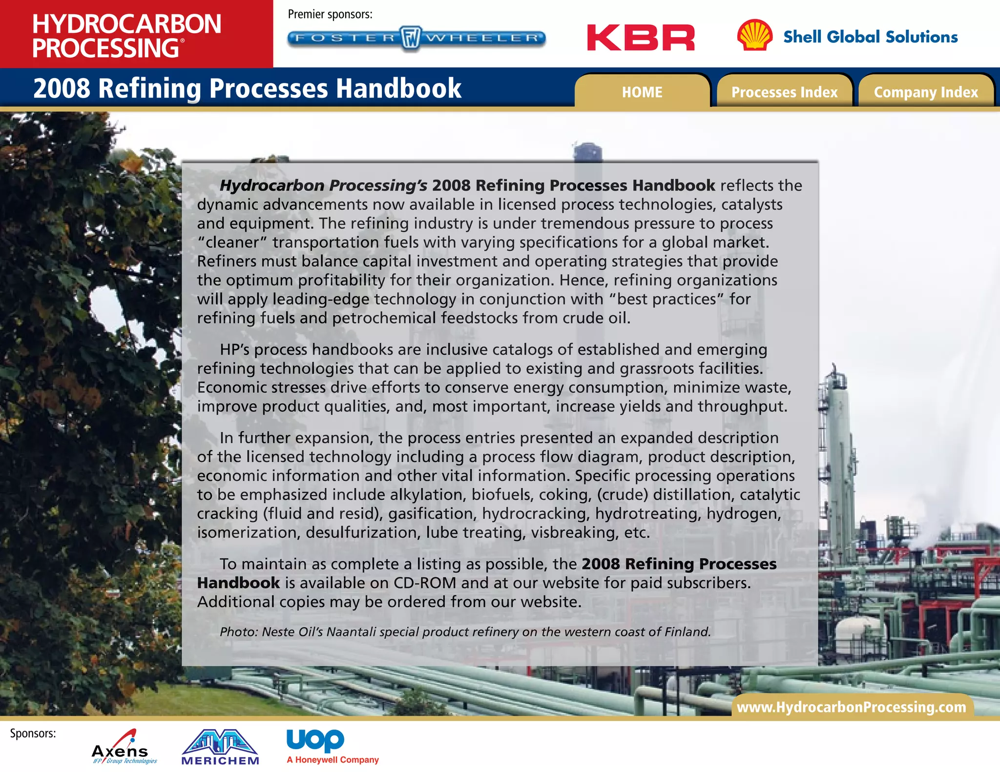
The document is a 2008 handbook from Hydrocarbon Processing that provides information on refining processes. It reflects advancements in licensed refining technologies, catalysts, and equipment. Refiners must balance investments and strategies to optimize profitability while producing cleaner transportation fuels for a global market. The handbook is a catalog of established and emerging refining technologies that can be applied to existing and new refineries. It provides expanded descriptions and information for various refining operations and processes.


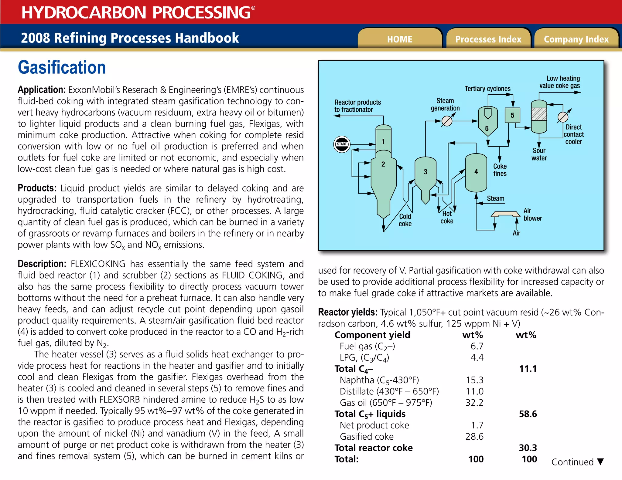
![Fuel gas production: Steam and air gasification of coke produced in the
reactor generates a large fuel gas stream that is rich in CO/H2, which
can be used as fuel. Fuel gas production consistent with the above yields
for a 31,000 bpd FLEXICOKING Unit is:
Flexigas production: 1,580 MBtu/hr [460 MW (th)]
Flexigas heating value: 128 Btu/SCF
H2S content: 10 wppm
Competitive advantages:
• Integrated coking and gasification technology that yields the same
valuable liquid products as other coking processes but produces clean
fuel gas instead of high-sulfur coke.
• Fluid bed process with coke transferred pneumatically and con-
tained within fluid solids reactors and product silos.
Gasification, continued
click here to e-mail for more information
• Environmental advantages with lower SOx, NOx, and particulates
emissions than conventional delayed coking processes
• Much lower investment and more reliable than delayed coking
plus partial oxidation or direct gasification of solids or heavy feeds. Par-
ticularly attractive for SAGD tar sands upgrading with large fuel require-
ments.
Reference: Kamienski, P. W. , S. Massenzio and M. de Wit, “Coking
without the coke,” Hydrocarbon Engineering, March 2008.
Kamienski, P. W. , S. Massenzio and M. de Wit, “FLEXICOKING: Inte-
grated Coking and Gasification Technology,” ERTC Coking and gasifica-
tion Conference, Rome, April 21–22, 2008.
Licensor: ExxonMobil Research and Engineering Co.](https://image.slidesharecdn.com/refiningprocessflowunits-230327031730-d024f858/75/Refining-process-flow-units-pdf-152-2048.jpg)