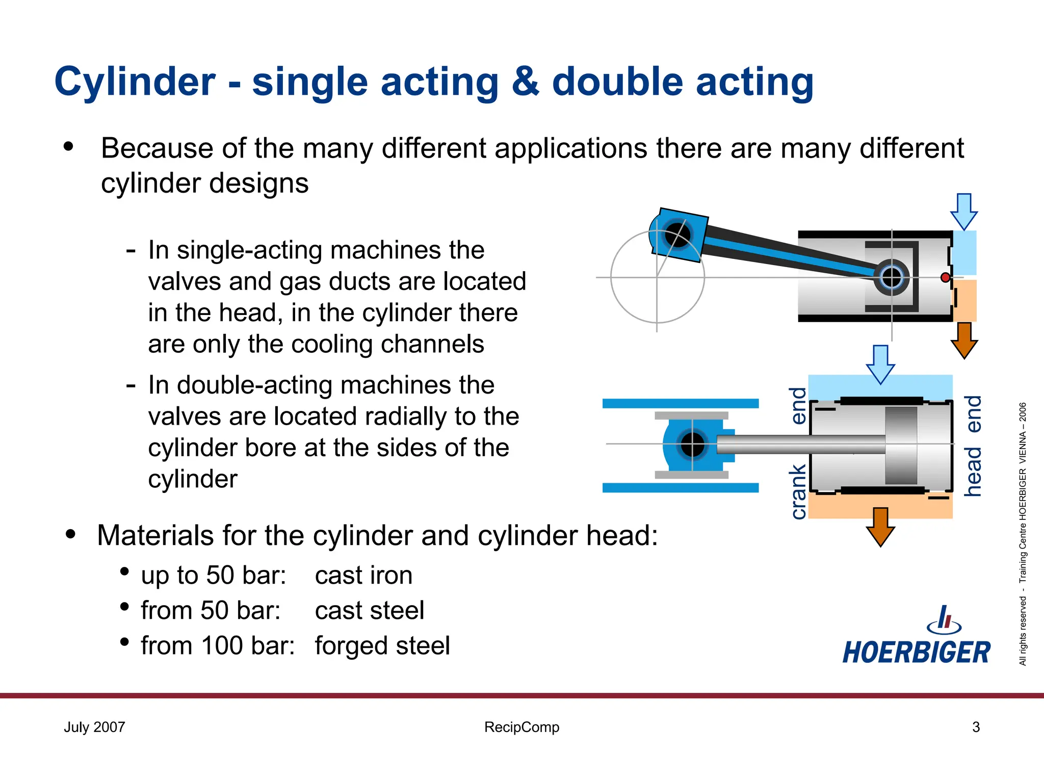
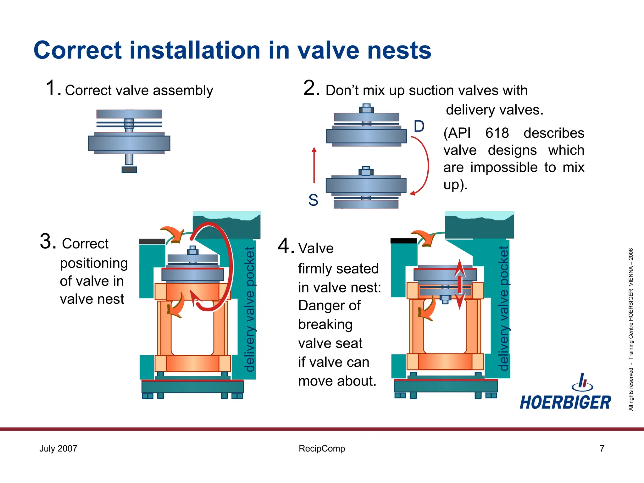
Reciprocating Compressor Valves
All
rights
reserved
-
Training
Centre
HOERBIGER
VIENNA
–
2006
2
RecipComp
July 2007
cooling water
channels
cylinder
diameter
suction duct
discharge duct
discharge valve nest
discharge valve
valve cage
valve cover
valve cover
valve cage
suction valve
suction valve nest
piston
piston rings
cylinder cover
cylinder liner
diaphragm cylinder
suction valve with unloader
piston rod
distance piece
piston rod
packings
Cylinder - assembly
All
rights
reserved
-
Training
Centre
HOERBIGER
VIENNA
–
2006
3
RecipComp
July 2007
head
end
crank
end
Cylinder - single acting & double acting
• Because of the many different applications there are many different
cylinder designs
• Materials for the cylinder and cylinder head:
• up to 50 bar: cast iron
• from 50 bar: cast steel
• from 100 bar: forged steel
- In single-acting machines the
valves and gas ducts are located
in the head, in the cylinder there
are only the cooling channels
- In double-acting machines the
valves are located radially to the
cylinder bore at the sides of the
cylinder
All
rights
reserved
-
Training
Centre
HOERBIGER
VIENNA
–
2006
4
RecipComp
July 2007
Closing Elements
Plates - rings - stripes - reeds - poppets - cones - balls ....
traditionally made of steel, today increasingly of fibre-reinforced plastics.
Closing elements of HOERBIGER Valves are:
steel plates profiled plastic rings plastic plates
poppets reeds flapper plates
Valve types for recips
All
rights
reserved
-
Training
Centre
HOERBIGER
VIENNA
–
2006
5
RecipComp
July 2007
suction Valve
Unloader
Actuator
DS
discharge Valve
exploded view
Suction valve and discharge valve
All
rights
reserved
-
Training
Centre
HOERBIGER
VIENNA
–
2006
6
RecipComp
July 2007
Requirements in Cylinder Design:
Installation in the valve nest
• easy valve installation and removal
• low pressure losses in valves and
valve pockets
• small clearance volumes
• the valve cage or the jack bolt
arrangement must have adequately
sized openings for the gas flow.
All
rights
reserved
-
Training
Centre
HOERBIGER
VIENNA
–
2006
7
RecipComp
July 2007
3. Correct
positioning
of valve in
valve nest
delivery
valve
pocket 4.Valve
firmly seated
in valve nest:
Danger of
breaking
valve seat
if valve can
move about.
delivery
valve
pocket
1.Correct valve assembly 2. Don’t mix up suction valves with
delivery valves.
S
D (API 618 describes
valve designs which
are impossible to mix
up).
Correct installation in valve nests
All
rights
reserved
-
Training
Centre
HOERBIGER
VIENNA
–
2006
8
RecipComp
July 2007
Jackbolt failure and consequential damage
Incorrect installation
All
rights
reserved
-
Training
Centre
HOERBIGER
VIENNA
–
2006
9
RecipComp
July 2007
Incorrect installation in the valve nest
• Valve Installation - Causes of LOOSE VALVES
• Wrong assembly sequence of valve cage, cage clamping bolts (jacking
bolts) and valve cover bolts
• Correct sequence:
1. tighten the valve cover bolts to the specified torque, with valve cage
clamping bolts (jacking bolts) withdrawn
2. tighten the valve cage clamping bolts to the specified torque
• Missing or defective gaskets
• Height of valves or valve cages too low after overhaul
• Gas tightness in valve nest, if valves are installed without gaskets
• Adequate quality of sealing surfaces of valve and valve nest, grinding-in
may be required
• For this reason the contact surface of HOERBIGER valves
are finished to N5 or N6 quality (HN150).
All
rights
reserved
-
Training
Centre
HOERBIGER
VIENNA
–
2006
10
RecipComp
July 2007
displacement [%]
0
5
10
15
20
25
30
0% 20% 40% 60% 80% 100%
pressure
[bar]
Area bordered
by the red line:
Indicated work
of cylinder end
suction
pressure
discharge
pressure
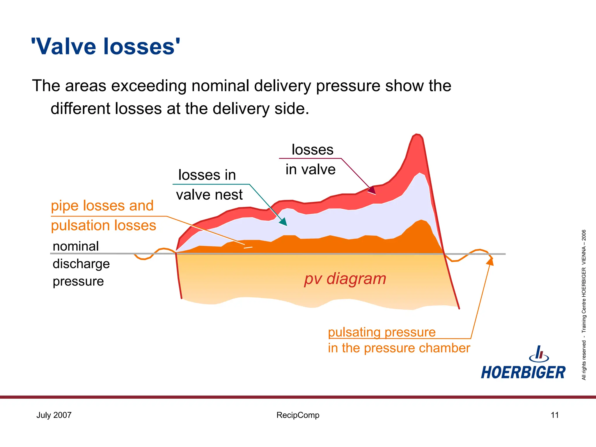
A certain percentage of the indicated power is lost due to:
Discharge losses
Total Gas Flow Losses in Indicator Diagram
'Valve losses'
Suction losses
All
rights
reserved
-
Training
Centre
HOERBIGER
VIENNA
–
2006
11
RecipComp
July 2007
The areas exceeding nominal delivery pressure show the
different losses at the delivery side.
losses
in valve
pipe losses and
pulsation losses
nominal
discharge
pressure
pulsating pressure
in the pressure chamber
losses in
valve nest
pv diagram
'Valve losses'
All
rights
reserved
-
Training
Centre
HOERBIGER
VIENNA
–
2006
12
RecipComp
July 2007
The shape of the valve nest in the cylinder has a considerable influence
on total gas flow losses. In the calculation of total flow losses with the
help of the TKK, the valve nest shape can be taken into account with
Pocket Factors.
Two examples for considerable flow losseshigh pocket factors.
Shape of valve nest and 'valve losses'
All
rights
reserved
-
Training
Centre
HOERBIGER
VIENNA
–
2006
13
RecipComp
July 2007
Common pocket shape and 'valve losses'
Low losses in the cylinder nests can be achieved by minimal restriction
of gas flow into cylinder,
• by wide passage areas
• by pockets or recesses in the cylinder head.
All
rights
reserved
-
Training
Centre
HOERBIGER
VIENNA
–
2006
14
RecipComp
July 2007
Cylinder head protrudes
until here into cylinder
end of contact area
of piston rings retracted piston
Cylinder head,
retracted
retracted piston
Narrow ports and gaps are restricting the gas flow too much.
Shading of valve nest by cylinder head
All
rights
reserved
-
Training
Centre
HOERBIGER
VIENNA
–
2006
15
RecipComp
July 2007
0% 10% 20% 30% 40%
Most of the failures can
be detected
by monitoring
Results of a reliability study of
reciprocating hydrogen compressors
Causes for unscheduled shutdowns
16
Reciprocating Compressors
The END

Reciprocating Compressor Cylinder Valves