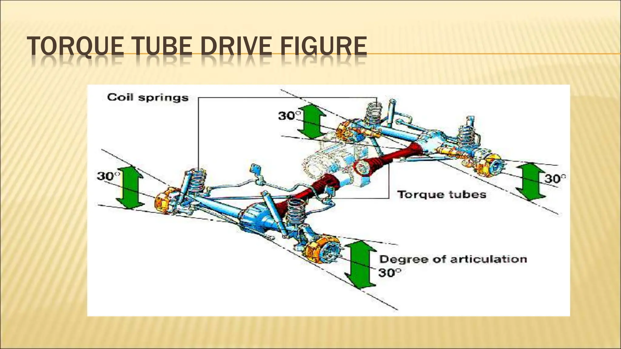
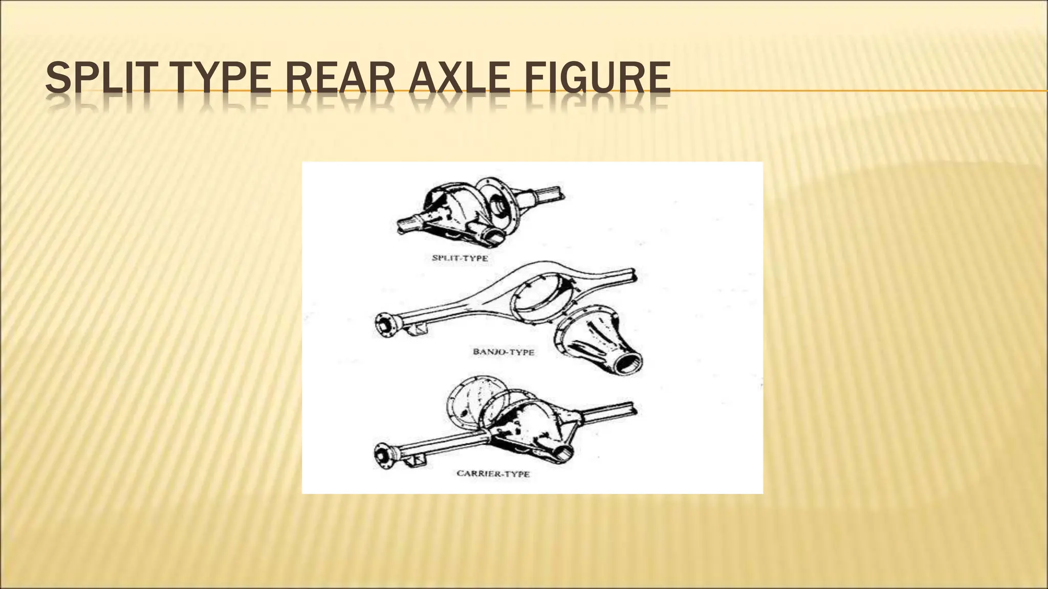
REAR AXLE AND FINAL DRIVE
•CONTENTS
1. REAR AXLE
2. Forces on rear axle
3. Types of rear axle construction
4. Rear axle drives
5. Types of rear axle casing
6. FINAL DRIVE
7. Differential
8. Types of gears for final drive
9. PROPELLER SHAFT
10. Parts of propeller shaft
11. Improvements in transmission system
REAR AXLE
• Rear Axles are structural members on which
Rear wheels are mounted on bearings.
• The weight of the body of the automobile and
load due to the occupants is transmitted
through springs to the axle casing.
FORCES AND TORQUES ON THE REAR AXLE
1. Weight of the Body
2. Driving thrust
3. Torque Reaction
4. Side thrust
1. WEIGHT OF THE BODY
• Rear axle behaves like a beam supported at
the ends and loaded at two points.
• The load coming on the axle is due to the
weight of the body being transmitted through
the suspension springs.
• Weight causes shear force and bending on
the wheels.
2. DRIVING THRUST
• Torque produced by the engine causes the
thrust on the wheels. This force is responsible
for the forward motion of the vehicle.
• The drive force from the wheels is transmitted to
the body or chassis by means of Radius rods or
thrust members. These members are in
longitudinal direction connecting axle casing
and the body.
3. TORQUE REACTION
• Torque reaction occurs due to the resistance offered by
the wheels to the motion. This causes a torque produced
on the axle in the counter clockwise direction when
viewed from the left side of the vehicle rear wheel axle.
• The torque produced by the braking torque is just the
opposite to the torque reaction.
• The torque reaction is opposed by Panhard rod which
connects the Rear axle to the vehicle body or chassis and
prevents excessive bending load coming onto the
propeller shaft.
4. SIDE THRUST
• Side thrust comes mainly when the vehicle is
taking a turn or when the vehicle is moving
along an laterally inclined surface.
• The side thrust coming on to the axle can be
taken by Panhard rod.
LOADS COMING ONTO LIVE REAR AXLE SHAFT
• Shearing force due to vehicle weight
• Bending moment due to the offset of the wheel
and the suspension.
• End thrust due to the side forces due to
cornering, side wind etc.
• Bending moment due to end thrust and reaction
from the tires.
• Driving torque.
TYPES OF REAR AXLE SUPPORTING
• Semi floating axle
• Full floating axle
• Three quarter floating axle
1. SEMI-FLOATING AXLE
• The wheel hub is connected directly to the rear axle.
• All the loads are taken by the rear axle (Shearing, Bending, End
thrust, Driving torque and brake torque).
• Advantages
• The semi floating axle is the simplest and cheapest and they
are widely used in cars.
• Disadvantages
• The axle has to be designed for carrying higher loads i.e.
they are of higher diameter for the same torque transmitted by
other types of axle supporting.
SEMI FLOATING AXLE FIGURE
2. FULL FLOATING AXLE
• The wheels hubs are mounted directly onto the axle casing and are
supported by two taper roller bearings.
• The load on the axle is very less. It need to take only the drive torque.
• Advantages
• These are very robust type and are used for heavy vehicles.
• Axle shaft carry only the drive torque so their failure does not affect
the vehicle wheels.
• Vehicle can be towed with the broken axle shaft.
• Axle shaft can be replaced by without jacking.
• Disadvantage
• Costliest type of axle supporting.
FULL FLOATING AXLE FIGURE
3. THREE QUARTER FLOATING AXLE
• The bearing is mounted between the axle and the axle casing.
• The axle shaft has to take drive torque and the end loads.
• The axle casing will take Bending an shearing forces.
• Advantages
• At one time this axle type was commonly used for cars and
light commercial vehicles.
• Disadvantages
• These axles are no longer preferred. instead semi floating
axles are used.
THREE QUARTER FLOATING AXLE FIGURE
REAR AXLE DRIVES
1. Hotchkiss Drive
2. Torque tube drive
1. HOTCHKISS DRIVE
• Simplest and most widely used rear axle drive.
• The suspension springs take torque reaction driving thrust and side thrust
• Construction
• Propeller shaft with two universal joints and a sliding joint. The spring is fixed
rigidly in the middle onto the frame. The drive torque is transmitted through the
front half of the springs.
• The front end of the leaf suspension is rigidly fixed onto the frame while the rear
is connected via a shackle.
• Two universal joints are used to avoid the bending of the propeller shaft due to
the torque reaction.
• Sliding joint is provided to accommodate for the variation of the length in the
transmission shaft.
HOTCHKISS DRIVE FIGURE
2. TORQUE TUBE DRIVE
• Torque reaction, Braking torque and drive thrust are taken by Torque
tube.
• The suspension springs are taking only the side thrust and body weight.
• Construction
• One end of the torque tube is attached to the axle casing while the other
end is spherical and fits into the cup on the frame. The torque tube
encloses the propeller shaft.
• Torque tube takes the torque reaction and centre line of the bevel pinion
shaft always passes through the centre of the spherical cup.
• Single universal joint is used in the transmission drive because the
universal joint is situated exactly at the centre of the spherical cup.
• No sliding joint is provided since the pinion shaft and the propeller shaft
moves same center ( spherical cup).
TORQUE TUBE DRIVE FIGURE
REAR AXLE CASINGS
1. Split type.
2. Banjo or Separate carrier type.
3. Salisbury or Integral Carrier type.
1. SPLIT TYPE
• The axle casing is made in two halves and
then bolted together for assembly. But the
main disadvantage is whole rear axle has to
be removed as a unit and reassembled in
case of a fault. This kind is no longer used
now.
SPLIT TYPE REAR AXLE FIGURE
2. BANJO OR SEPARATE CARRIER
• Axle is made as a single piece The complete
differential unit is separate unit and is bolted
to the axle casing and the two shafts are put
from two sides.
• In case of repair the shafts can be taken from
two sides and differential can be removed
easily.
BANJO TYPE REAR AXLE FIGURE
3. SALISBURY OR INTERGRAL CARRIER TYPE
• This is similar to the banjo type except that
the permanent housing tubes are pressed
and welded onto the sides.
• This is the most commonly used kind of rear
wheel driven cars.
SALISBURY TYPE REAR AXLE FIGURE
FINAL DRIVE
• Final drive is used to provide a permamanent speed
reduction and to turn the drive through 90 degree.
• The reduction ratio provided by the final drive is 4:1 for
cars and 10:1 for heavy vehicles.
• The reduction ration upto 7:1 can be done in single stage
and above that is done in two stages. This is done to
reduce the size of the gear and to improve the ground
clearance.
• Final drive can be bevel pinion and crown wheel or worm
and worm wheel arrangement.
TYPES OF GEARS FOR FINAL DRIVE
1. Straight Bevel Gears.
2. Spiral Bevel Gears.
3. Hypoid Bevel Gears
4. Worm and Worm Wheel Arrangement.
1. STRAIGHT BEVEL GEARS
• The gears have straight teeth.
• Advantages
• Simplest and Cheapest
• Disadvantages
• Uneven transmission due to contact of single
pair of teeth.
• Less load carrying capacity.
STRAIGHT BEVEL GEARS
2. SPIRAL BEVEL GEARS
• Spiral bevel gears have curved teeth so have
greater number of teeth in contact. The gear
tooth have sliding motion also in between.
• Advantages
• Silent Running.
• They are able to take more loads.
SPIRAL BEVEL GEARS FIGURE
3. HYPOID GEARS
• The structure of the teeth have hyperboloid in shape. Hyperboloid
is obtained by rotating a hyperbola Abut an offset axis.
• The gears transmit motion at right at right angles but the axis of
the gears don’t intersect but they lie at an offset distance.
• Advantages
• The hypoid gears permit a lower position of the propeller shaft
and allow more lower chassis height or less chassis height as the
case may be.
• Hypoid gears increases the loads capacity of the gears.
• Disadvantage
• Expensive difficult to assemble and need special lubricant due to
the greater sliding action between the gears.
HYPOID GEARS FIGURE
4. WORM AND WORM WHEEL
• Worm is a single or multi started thread which drives the worm wheel
which has teeth over the periphery of the wheel.
• Higher gear ratios are possible in worm and worm wheel arrangement.
• Advantages
• Worm and Worm wheel arrangement is particularly used in heavy
vehicle where higher gear ratios of greater than 6 needed
• Strong and efficient drive
• Single stage reduction is only necessary for higher gear ratios also.
• Worm gears give low chassis height or more ground clearance as the
case may be.
• Disadvantages
• Higher cost and more weight than bevel gear
• Mechanical efficiency is lower than bevel gear for single stage reduction
WORM AND WORM WHEEL FIGURE
DIFFERENTIAL
• Differential is the gear mechanism which
allows the wheels to turn at different speeds
according to the radius of curvature they are
negotiating. The differential allows the
wheels to rotate at different speeds using
planetary gear mechanism and give different
speeds according to the load coming onto
the different wheels.
DIFFERENTIAL FIGURE
PROPELLER SHAFT
• Propeller shaft transmits the drive from the
engine to the drive axles.
• Propeller shaft consists of three main parts
1. Shaft
2. Universal joints
3. Slip joints
PROPELLER SHAFT FIGURE
1. SHAFT
• Shaft is the member which transmits the power.
It needs to withstand torsional loads mainly.
Normally the shafts are of tubular cross
sections. They needs to be well balanced to
avoid whirling at high speeds.
• Materials used for shafts are steel aluminum or
composites materials.
• The mass of the shaft has to be made small to
avoid high rotational moment of inertia which
2. UNIVERSAL JOINTS
• Universal joints are used to transmit power
between inclined shafts.
• Different kinds of universal joints are
• Hooks joint
• Hooks joint with needle roller bearings
• Perfect circle U joints
• Flexible Ring universal joints
CONSTANT VELOCITY JOINTS
• Rzepppa joint
• Tripoid joint
3. SLIP JOINT
• Slip joint is provided to accommodate for the
variations of the length of the propeller shaft.
This is necessary due to the relative
movements of the axle and the vehicle body
due to the suspension action.
• The slip joint is formed by internal splines on
the sleeve and external splines on the
propeller shaft.
SLIP JOINT FIGURE
IMPROVEMENTS IN TRANSMISSION SYSTEM
• Viscous coupling – which responds to the
difference in the speed. The torque transmitted
depends on the slip between the shafts.
• It consist of silicon based oil which thickens on
shearing action. It consist of cylindrical chamber
of fluid with a stack of perforated rotating discs.
The discs are connected alternatively to the
inside and outside shaft and chamber. The
VISCOUS COUPLING FIGURE
Thank you

reareaxle-121123141344-phpapp0trtertet2.ppt

  • 1.
    REAR AXLE ANDFINAL DRIVE
  • 2.
    •CONTENTS 1. REAR AXLE 2.Forces on rear axle 3. Types of rear axle construction 4. Rear axle drives 5. Types of rear axle casing 6. FINAL DRIVE 7. Differential 8. Types of gears for final drive 9. PROPELLER SHAFT 10. Parts of propeller shaft 11. Improvements in transmission system
  • 3.
    REAR AXLE • RearAxles are structural members on which Rear wheels are mounted on bearings. • The weight of the body of the automobile and load due to the occupants is transmitted through springs to the axle casing.
  • 4.
    FORCES AND TORQUESON THE REAR AXLE 1. Weight of the Body 2. Driving thrust 3. Torque Reaction 4. Side thrust
  • 5.
    1. WEIGHT OFTHE BODY • Rear axle behaves like a beam supported at the ends and loaded at two points. • The load coming on the axle is due to the weight of the body being transmitted through the suspension springs. • Weight causes shear force and bending on the wheels.
  • 6.
    2. DRIVING THRUST •Torque produced by the engine causes the thrust on the wheels. This force is responsible for the forward motion of the vehicle. • The drive force from the wheels is transmitted to the body or chassis by means of Radius rods or thrust members. These members are in longitudinal direction connecting axle casing and the body.
  • 7.
    3. TORQUE REACTION •Torque reaction occurs due to the resistance offered by the wheels to the motion. This causes a torque produced on the axle in the counter clockwise direction when viewed from the left side of the vehicle rear wheel axle. • The torque produced by the braking torque is just the opposite to the torque reaction. • The torque reaction is opposed by Panhard rod which connects the Rear axle to the vehicle body or chassis and prevents excessive bending load coming onto the propeller shaft.
  • 8.
    4. SIDE THRUST •Side thrust comes mainly when the vehicle is taking a turn or when the vehicle is moving along an laterally inclined surface. • The side thrust coming on to the axle can be taken by Panhard rod.
  • 9.
    LOADS COMING ONTOLIVE REAR AXLE SHAFT • Shearing force due to vehicle weight • Bending moment due to the offset of the wheel and the suspension. • End thrust due to the side forces due to cornering, side wind etc. • Bending moment due to end thrust and reaction from the tires. • Driving torque.
  • 10.
    TYPES OF REARAXLE SUPPORTING • Semi floating axle • Full floating axle • Three quarter floating axle
  • 11.
    1. SEMI-FLOATING AXLE •The wheel hub is connected directly to the rear axle. • All the loads are taken by the rear axle (Shearing, Bending, End thrust, Driving torque and brake torque). • Advantages • The semi floating axle is the simplest and cheapest and they are widely used in cars. • Disadvantages • The axle has to be designed for carrying higher loads i.e. they are of higher diameter for the same torque transmitted by other types of axle supporting.
  • 12.
  • 13.
    2. FULL FLOATINGAXLE • The wheels hubs are mounted directly onto the axle casing and are supported by two taper roller bearings. • The load on the axle is very less. It need to take only the drive torque. • Advantages • These are very robust type and are used for heavy vehicles. • Axle shaft carry only the drive torque so their failure does not affect the vehicle wheels. • Vehicle can be towed with the broken axle shaft. • Axle shaft can be replaced by without jacking. • Disadvantage • Costliest type of axle supporting.
  • 14.
  • 15.
    3. THREE QUARTERFLOATING AXLE • The bearing is mounted between the axle and the axle casing. • The axle shaft has to take drive torque and the end loads. • The axle casing will take Bending an shearing forces. • Advantages • At one time this axle type was commonly used for cars and light commercial vehicles. • Disadvantages • These axles are no longer preferred. instead semi floating axles are used.
  • 16.
  • 17.
    REAR AXLE DRIVES 1.Hotchkiss Drive 2. Torque tube drive
  • 18.
    1. HOTCHKISS DRIVE •Simplest and most widely used rear axle drive. • The suspension springs take torque reaction driving thrust and side thrust • Construction • Propeller shaft with two universal joints and a sliding joint. The spring is fixed rigidly in the middle onto the frame. The drive torque is transmitted through the front half of the springs. • The front end of the leaf suspension is rigidly fixed onto the frame while the rear is connected via a shackle. • Two universal joints are used to avoid the bending of the propeller shaft due to the torque reaction. • Sliding joint is provided to accommodate for the variation of the length in the transmission shaft.
  • 19.
  • 20.
    2. TORQUE TUBEDRIVE • Torque reaction, Braking torque and drive thrust are taken by Torque tube. • The suspension springs are taking only the side thrust and body weight. • Construction • One end of the torque tube is attached to the axle casing while the other end is spherical and fits into the cup on the frame. The torque tube encloses the propeller shaft. • Torque tube takes the torque reaction and centre line of the bevel pinion shaft always passes through the centre of the spherical cup. • Single universal joint is used in the transmission drive because the universal joint is situated exactly at the centre of the spherical cup. • No sliding joint is provided since the pinion shaft and the propeller shaft moves same center ( spherical cup).
  • 21.
  • 22.
    REAR AXLE CASINGS 1.Split type. 2. Banjo or Separate carrier type. 3. Salisbury or Integral Carrier type.
  • 23.
    1. SPLIT TYPE •The axle casing is made in two halves and then bolted together for assembly. But the main disadvantage is whole rear axle has to be removed as a unit and reassembled in case of a fault. This kind is no longer used now.
  • 24.
    SPLIT TYPE REARAXLE FIGURE
  • 25.
    2. BANJO ORSEPARATE CARRIER • Axle is made as a single piece The complete differential unit is separate unit and is bolted to the axle casing and the two shafts are put from two sides. • In case of repair the shafts can be taken from two sides and differential can be removed easily.
  • 26.
    BANJO TYPE REARAXLE FIGURE
  • 27.
    3. SALISBURY ORINTERGRAL CARRIER TYPE • This is similar to the banjo type except that the permanent housing tubes are pressed and welded onto the sides. • This is the most commonly used kind of rear wheel driven cars.
  • 28.
  • 29.
    FINAL DRIVE • Finaldrive is used to provide a permamanent speed reduction and to turn the drive through 90 degree. • The reduction ratio provided by the final drive is 4:1 for cars and 10:1 for heavy vehicles. • The reduction ration upto 7:1 can be done in single stage and above that is done in two stages. This is done to reduce the size of the gear and to improve the ground clearance. • Final drive can be bevel pinion and crown wheel or worm and worm wheel arrangement.
  • 30.
    TYPES OF GEARSFOR FINAL DRIVE 1. Straight Bevel Gears. 2. Spiral Bevel Gears. 3. Hypoid Bevel Gears 4. Worm and Worm Wheel Arrangement.
  • 31.
    1. STRAIGHT BEVELGEARS • The gears have straight teeth. • Advantages • Simplest and Cheapest • Disadvantages • Uneven transmission due to contact of single pair of teeth. • Less load carrying capacity.
  • 32.
  • 33.
    2. SPIRAL BEVELGEARS • Spiral bevel gears have curved teeth so have greater number of teeth in contact. The gear tooth have sliding motion also in between. • Advantages • Silent Running. • They are able to take more loads.
  • 34.
  • 35.
    3. HYPOID GEARS •The structure of the teeth have hyperboloid in shape. Hyperboloid is obtained by rotating a hyperbola Abut an offset axis. • The gears transmit motion at right at right angles but the axis of the gears don’t intersect but they lie at an offset distance. • Advantages • The hypoid gears permit a lower position of the propeller shaft and allow more lower chassis height or less chassis height as the case may be. • Hypoid gears increases the loads capacity of the gears. • Disadvantage • Expensive difficult to assemble and need special lubricant due to the greater sliding action between the gears.
  • 36.
  • 37.
    4. WORM ANDWORM WHEEL • Worm is a single or multi started thread which drives the worm wheel which has teeth over the periphery of the wheel. • Higher gear ratios are possible in worm and worm wheel arrangement. • Advantages • Worm and Worm wheel arrangement is particularly used in heavy vehicle where higher gear ratios of greater than 6 needed • Strong and efficient drive • Single stage reduction is only necessary for higher gear ratios also. • Worm gears give low chassis height or more ground clearance as the case may be. • Disadvantages • Higher cost and more weight than bevel gear • Mechanical efficiency is lower than bevel gear for single stage reduction
  • 38.
    WORM AND WORMWHEEL FIGURE
  • 39.
    DIFFERENTIAL • Differential isthe gear mechanism which allows the wheels to turn at different speeds according to the radius of curvature they are negotiating. The differential allows the wheels to rotate at different speeds using planetary gear mechanism and give different speeds according to the load coming onto the different wheels.
  • 40.
  • 41.
    PROPELLER SHAFT • Propellershaft transmits the drive from the engine to the drive axles. • Propeller shaft consists of three main parts 1. Shaft 2. Universal joints 3. Slip joints
  • 42.
  • 43.
    1. SHAFT • Shaftis the member which transmits the power. It needs to withstand torsional loads mainly. Normally the shafts are of tubular cross sections. They needs to be well balanced to avoid whirling at high speeds. • Materials used for shafts are steel aluminum or composites materials. • The mass of the shaft has to be made small to avoid high rotational moment of inertia which
  • 44.
    2. UNIVERSAL JOINTS •Universal joints are used to transmit power between inclined shafts. • Different kinds of universal joints are • Hooks joint • Hooks joint with needle roller bearings • Perfect circle U joints • Flexible Ring universal joints
  • 45.
    CONSTANT VELOCITY JOINTS •Rzepppa joint • Tripoid joint
  • 46.
    3. SLIP JOINT •Slip joint is provided to accommodate for the variations of the length of the propeller shaft. This is necessary due to the relative movements of the axle and the vehicle body due to the suspension action. • The slip joint is formed by internal splines on the sleeve and external splines on the propeller shaft.
  • 47.
  • 48.
    IMPROVEMENTS IN TRANSMISSIONSYSTEM • Viscous coupling – which responds to the difference in the speed. The torque transmitted depends on the slip between the shafts. • It consist of silicon based oil which thickens on shearing action. It consist of cylindrical chamber of fluid with a stack of perforated rotating discs. The discs are connected alternatively to the inside and outside shaft and chamber. The
  • 49.
  • 50.