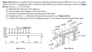
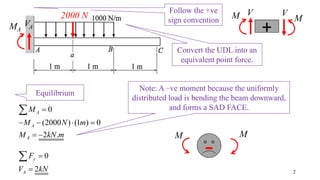
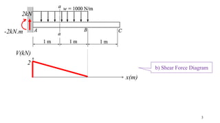
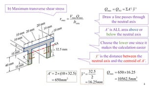
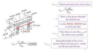
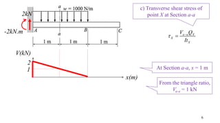
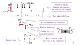
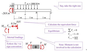
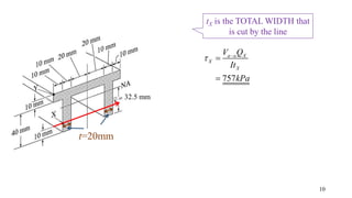
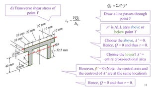
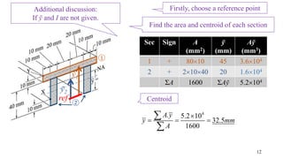
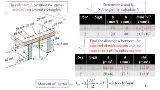
32.5 mm
Figure Q1 (a) shows a cantilever beam carrying a uniformly distributed load of 1000 N/m over a 2 m length
from A to B. The 1 m length from B to C carries no load and the cross-section of the beam is shown in Figure
Q1 (b). Given IN.A = 3.63105 mm4.
a) Determine the reactions at the support A.
b) Draw the shear force diagram of the entire beam.
c) Calculate the absolute maximum shearing stress of the beam.
d) Consider section a – a, determine the shear stress at point X as in Figure Q1 (b).
e) Explain why shearing stress due to bending at point Y is zero at any location along the beam span.
Figure Q1 (a) Figure Q1 (b)
Follow the +ve
sign convention
0
2
y
A
F
V kN



Note: A –ve moment because the uniformly
distributed load is bending the beam downward,
and forms a SAD FACE.
Equilibrium
2
VAMA
V
M
+
VM
0
(2000 ) (1 ) 0
2 .
A
A
A
M
M N m
M kN m

   
 

MM
Convert the UDL into an
equivalent point force.
-
2000 N
3
2kN
-2kN.m
b) Shear Force Diagram
V(kN)
x(m)
2
32.5 mm
4
Draw a line passes through
the neutral axis
Choose the lower one since it
makes the calculation easier
max ' 'NAQ Q A y   
A’ is ALL area above or
below the neutral axis
ӯ’ is the distance between the
neutral axis and the centroid of A’.
2
' 2 (10 32.5)
650
A
mm
  

32.5
'
2
16.25
y
mm


max
3
650 16.25
10562.5
Q
mm
 

ӯ’
ӯ’
b) Maximum transverse shear stress
max max
max
min
V Q
It
 
32.5 mm
Maximum transverse shear stress
5
Draw a line passes through
the neutral axis
Note that it is also the tmin of
the entire cross-section.
max max
max
min
V Q
It
 
t is the TOTAL WIDTH that
is cut by the line
t=20mm
Along the height of the cross-
section, there are only two t, which
are 80 mm and 20 mm.
max max
max
min
2.91
V Q
MPa
It
  
6
2kN
-2kN.m
At Section a-a, x = 1 m
V(kN)
x(m)
2
1
From the triangle ratio,
Va-a = 1 kN
c) Transverse shear stress of
point X at Section a-a
a a X
X
X
V Q
It
 

7
2kN
-2kN.m
Alternatively, cut
Section a-a, take the
FBD on the left or right
Say, take the left one
Va-a
Ma-a
1kN
Calculate the equivalent force0.5m
Internal loadings
0
2 1 0
1
y
a a
a a
F
V
V kN



  


Equilibrium
Follow the +ve
sign convention
V
M
+
VM
Note: Moment is not
involved in the calculation
8
2kN
-2kN.m
Say, take the right one
Va-aMa-a
1kN
Calculate the equivalent force0.5m
Internal loadings
0
1 0
1
y
a a
a a
F
V
V kN



 

Equilibrium
Follow the +ve
sign convention
V
M
+
VM Note: Moment is not
involved in the calculation
32.5 mm
9
Draw a line passes through
point X
Choose the lower one since it
makes the calculation easier
' 'XQ A y  
A’ is ALL area above or
below point X
ӯ’ is the distance between the
neutral axis and the centroid of A’.
2
' 2 (10 10)
200
A
mm
  

' 32.5 5
27.5
y
mm
 

3
200 27.5
5500
XQ
mm
 

ӯ’
ӯ’
c) Transverse shear stress of
point X at Section a-a
a a X
X
X
V Q
It
 

32.5 mm
10
tX is the TOTAL WIDTH that
is cut by the line
t=20mm
757
a a X
X
X
V Q
It
kPa
 


32.5 mm
11
Draw a line passes through
point Y
Choose the lower? A’ =
entire cross-sectional area
' 'YQ A y  
A’ is ALL area above or
below point Y
However, ӯ’ = 0 (Note: the neutral axis and
the centroid of A’ are at the same location).
d) Transverse shear stress of
point Y
Y
Y
Y
VQ
It
 
Choose the above, A’ = 0.
Hence, Q = 0 and thus τ = 0.
12
4
. 5.2 10
32.5
1600
A y
y mm
A

  


1
2
Find the area and centroid of each section
Firstly, choose a reference pointAdditional discussion:
If ӯ and I are not given.
ref
ӯ2
ӯ1
Sec Sign A
(mm2)
ӯ
(mm)
Aӯ
(mm3)
1 + 8010 45 3.6104
2 + 21040 20 1.6104
ΣA 1600 ΣAӯ 5.2104
Centroid
32.5 mm
13
3
2 5 4
3.63 10
12
tot
bh
I Ad mm
 
     
 
1
2
d1
Moment of Inertia
Find the distance d between the
centroid of each section and the
neutral axis of the entire section
Sec Sign A
(mm2)
d
(mm)
Ad2
(mm4)
1 + 8010 12.5 1104
2 + 2040 12.5 1104
Sec Sign b
(mm2)
h
(mm)
I=bh3/12
(mm4)
1 + 80 10 6.67103
2 + 20 40 1.07105
Determine b and h.
Subsequently, calculate I.
To calculate I, partition the cross-
section into several rectangles.
d2

4 transvere shear-asgn

  • 1.
    32.5 mm Figure Q1(a) shows a cantilever beam carrying a uniformly distributed load of 1000 N/m over a 2 m length from A to B. The 1 m length from B to C carries no load and the cross-section of the beam is shown in Figure Q1 (b). Given IN.A = 3.63105 mm4. a) Determine the reactions at the support A. b) Draw the shear force diagram of the entire beam. c) Calculate the absolute maximum shearing stress of the beam. d) Consider section a – a, determine the shear stress at point X as in Figure Q1 (b). e) Explain why shearing stress due to bending at point Y is zero at any location along the beam span. Figure Q1 (a) Figure Q1 (b)
  • 2.
    Follow the +ve signconvention 0 2 y A F V kN    Note: A –ve moment because the uniformly distributed load is bending the beam downward, and forms a SAD FACE. Equilibrium 2 VAMA V M + VM 0 (2000 ) (1 ) 0 2 . A A A M M N m M kN m         MM Convert the UDL into an equivalent point force. - 2000 N
  • 3.
    3 2kN -2kN.m b) Shear ForceDiagram V(kN) x(m) 2
  • 4.
    32.5 mm 4 Draw aline passes through the neutral axis Choose the lower one since it makes the calculation easier max ' 'NAQ Q A y    A’ is ALL area above or below the neutral axis ӯ’ is the distance between the neutral axis and the centroid of A’. 2 ' 2 (10 32.5) 650 A mm     32.5 ' 2 16.25 y mm   max 3 650 16.25 10562.5 Q mm    ӯ’ ӯ’ b) Maximum transverse shear stress max max max min V Q It  
  • 5.
    32.5 mm Maximum transverseshear stress 5 Draw a line passes through the neutral axis Note that it is also the tmin of the entire cross-section. max max max min V Q It   t is the TOTAL WIDTH that is cut by the line t=20mm Along the height of the cross- section, there are only two t, which are 80 mm and 20 mm. max max max min 2.91 V Q MPa It   
  • 6.
    6 2kN -2kN.m At Section a-a,x = 1 m V(kN) x(m) 2 1 From the triangle ratio, Va-a = 1 kN c) Transverse shear stress of point X at Section a-a a a X X X V Q It   
  • 7.
    7 2kN -2kN.m Alternatively, cut Section a-a,take the FBD on the left or right Say, take the left one Va-a Ma-a 1kN Calculate the equivalent force0.5m Internal loadings 0 2 1 0 1 y a a a a F V V kN         Equilibrium Follow the +ve sign convention V M + VM Note: Moment is not involved in the calculation
  • 8.
    8 2kN -2kN.m Say, take theright one Va-aMa-a 1kN Calculate the equivalent force0.5m Internal loadings 0 1 0 1 y a a a a F V V kN       Equilibrium Follow the +ve sign convention V M + VM Note: Moment is not involved in the calculation
  • 9.
    32.5 mm 9 Draw aline passes through point X Choose the lower one since it makes the calculation easier ' 'XQ A y   A’ is ALL area above or below point X ӯ’ is the distance between the neutral axis and the centroid of A’. 2 ' 2 (10 10) 200 A mm     ' 32.5 5 27.5 y mm    3 200 27.5 5500 XQ mm    ӯ’ ӯ’ c) Transverse shear stress of point X at Section a-a a a X X X V Q It   
  • 10.
    32.5 mm 10 tX isthe TOTAL WIDTH that is cut by the line t=20mm 757 a a X X X V Q It kPa    
  • 11.
    32.5 mm 11 Draw aline passes through point Y Choose the lower? A’ = entire cross-sectional area ' 'YQ A y   A’ is ALL area above or below point Y However, ӯ’ = 0 (Note: the neutral axis and the centroid of A’ are at the same location). d) Transverse shear stress of point Y Y Y Y VQ It   Choose the above, A’ = 0. Hence, Q = 0 and thus τ = 0. Hence, Q = 0 and thus τ = 0.
  • 12.
    12 4 . 5.2 10 32.5 1600 Ay y mm A       1 2 Find the area and centroid of each section Firstly, choose a reference pointAdditional discussion: If ӯ and I are not given. ref ӯ2 ӯ1 Sec Sign A (mm2) ӯ (mm) Aӯ (mm3) 1 + 8010 45 3.6104 2 + 21040 20 1.6104 ΣA 1600 ΣAӯ 5.2104 Centroid
  • 13.
    32.5 mm 13 3 2 54 3.63 10 12 tot bh I Ad mm           1 2 d1 Moment of Inertia Find the distance d between the centroid of each section and the neutral axis of the entire section Sec Sign A (mm2) d (mm) Ad2 (mm4) 1 + 8010 12.5 1104 2 + 2040 12.5 1104 Sec Sign b (mm2) h (mm) I=bh3/12 (mm4) 1 + 80 10 6.67103 2 + 20 40 1.07105 Determine b and h. Subsequently, calculate I. To calculate I, partition the cross- section into several rectangles. d2