This document contains solutions to 11 problems involving the calculation of stresses, strains, elongations and dimensions of rods, wires and other structural elements under tensile loading conditions. The problems apply concepts of stress, strain, modulus of elasticity, Hooke's law and factor of safety to analyze steel, aluminum, nylon and other materials. The full solutions show the step-by-step working to determine values such as load, stress, elongation, diameter and length based on given material properties and loading/deformation parameters.


![PROPRIETARY MATERIAL. © 2012 The McGraw-Hill Companies, Inc. All rights reserved. No part of this Manual may be displayed,
reproduced, or distributed in any form or by any means, without the prior written permission of the publisher, or used beyond the limited
distribution to teachers and educators permitted by McGraw-Hill for their individual course preparation. A student using this manual is using it
without permission.
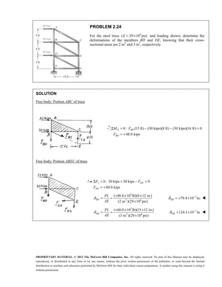
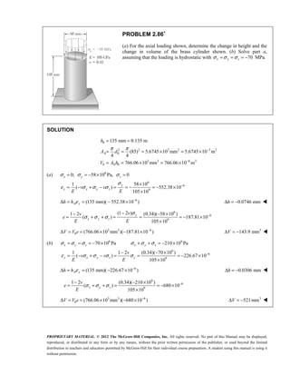
PROBLEM 2.33
An axial force of 200 kN is applied to the assembly shown by means of
rigid end plates. Determine (a) the normal stress in the aluminum shell,
(b) the corresponding deformation of the assembly.
SOLUTION
Let Pa = Portion of axial force carried by shell
Pb = Portion of axial force carried by core.
, or
a a a
a
a a
P L E A
P
E A L
δ δ
= =
, or
b b b
b
b b
P L E A
P
E A L
δ δ
= =
Thus, ( )
a b a a b b
P P P E A E A
L
δ
= + = +
with 2 2 3 2
2 3 2
[(0.060) (0.025) ] 2.3366 10 m
4
(0.025) 0.49087 10 m
4
a
b
A
A
π
π
−
−
= − = ×
= = ×
9 3 9 3
6
[(70 10 )(2.3366 10 ) (105 10 )(0.49087 10 )]
215.10 10
P
L
P
L
δ
δ
− −
= × × + × ×
= ×
Strain:
3
3
6 6
200 10
0.92980 10
215.10 10 215.10 10
δ
ε −
×
= = = = ×
× ×
P
L
(a) 9 3 6
(70 10 )(0.92980 10 ) 65.1 10 Pa
σ ε −
= = × × = ×
a a
E 65.1 MPa
a
σ =
(b) 3
(0.92980 10 )(300 mm)
L
δ ε −
= = × 0.279 mm
δ = ](https://image.slidesharecdn.com/chapter02-220614132946-84c47c56/85/Chapter02-pdf-36-320.jpg)
![PROPRIETARY MATERIAL. © 2012 The McGraw-Hill Companies, Inc. All rights reserved. No part of this Manual may be displayed,
reproduced, or distributed in any form or by any means, without the prior written permission of the publisher, or used beyond the limited
distribution to teachers and educators permitted by McGraw-Hill for their individual course preparation. A student using this manual is using it
without permission.
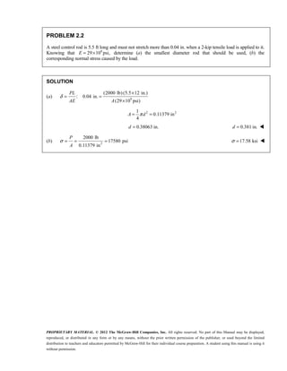
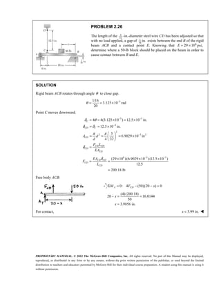
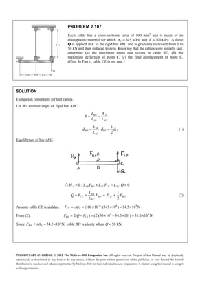
PROBLEM 2.34
The length of the assembly shown decreases by 0.40 mm when an axial
force is applied by means of rigid end plates. Determine (a) the magnitude
of the applied force, (b) the corresponding stress in the brass core.
SOLUTION
Let Pa = Portion of axial force carried by shell and Pb = Portion of axial force carried by core.
, or
a a a
a
a a
P L E A
P
E A L
δ δ
= =
, or
b b b
b
b b
P L E A
P
E A L
δ δ
= =
Thus, ( )
a b a a b b
P P P E A E A
L
δ
= + = +
with 2 2 3 2
2 3 2
[(0.060) (0.025) ] 2.3366 10 m
4
(0.025) 0.49087 10 m
4
a
b
A
A
π
π
−
−
= − = ×
= = ×
9 3 9 3 6
[(70 10 )(2.3366 10 ) (105 10 )(0.49087 10 )] 215.10 10
δ δ
− −
= × × + × × = ×
P
L L
with 0.40 mm, 300 mm
L
δ = =
(a) 6 3
0.40
(215.10 10 ) 286.8 10 N
300
P = × = × 287 kN
P =
(b)
9 3
6
3
(105 10 )(0.40 10 )
140 10 Pa
300 10
δ
σ
−
−
× ×
= = = = ×
×
b b
b
b
P E
A L
140.0MPa
σ =
b ](https://image.slidesharecdn.com/chapter02-220614132946-84c47c56/85/Chapter02-pdf-37-320.jpg)


![PROPRIETARY MATERIAL. © 2012 The McGraw-Hill Companies, Inc. All rights reserved. No part of this Manual may be displayed,
reproduced, or distributed in any form or by any means, without the prior written permission of the publisher, or used beyond the limited
distribution to teachers and educators permitted by McGraw-Hill for their individual course preparation. A student using this manual is using it
without permission.
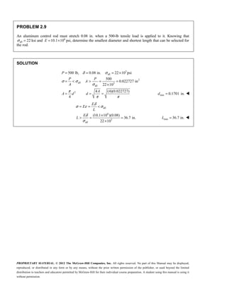
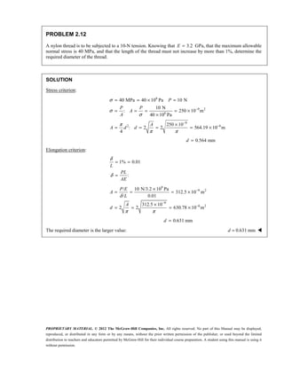
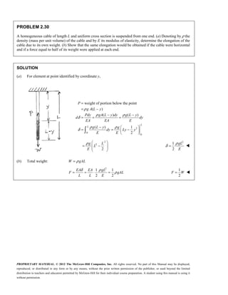
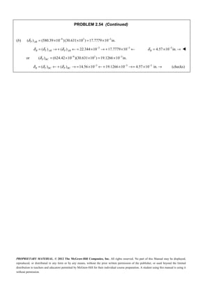
PROBLEM 2.69
The aluminum rod AD is fitted with a jacket that is used to apply a
hydrostatic pressure of 6000 psi to the 12-in. portion BC of the rod.
Knowing that 6
10.1 10
E = × psi and 0.36,
v = determine (a) the change in
the total length AD, (b) the change in diameter at the middle of the rod.
SOLUTION
6
6
6
6
6000 psi 0
1
( )
1
[ 6000 (0.36)(0) (0.36)( 6000)]
10.1 10
380.198 10
1
( )
1
[ (0.36)( 6000) 0 (0.36)( 6000)]
10.1 10
427.72 10
x z y
x x y z
y x y z
P
v v
E
v v
E
σ σ σ
ε σ σ σ
ε σ σ σ
−
−
= = − = − =
= − −
= − − − −
×
= − ×
= − + −
= − − + − −
×
= ×
Length subjected to strain : 12 in.
x L
ε =
(a) 6
(12)(427.72 10 )
y y
L
δ ε −
= = × 3
5.13 10 in.
l
δ −
= ×
(b) 6
(1.5)( 380.198 10 )
x x
d
δ ε −
= = − × 3
0.570 10 in.
d
δ −
= − × ](https://image.slidesharecdn.com/chapter02-220614132946-84c47c56/85/Chapter02-pdf-79-320.jpg)
![PROPRIETARY MATERIAL. © 2012 The McGraw-Hill Companies, Inc. All rights reserved. No part of this Manual may be displayed,
reproduced, or distributed in any form or by any means, without the prior written permission of the publisher, or used beyond the limited
distribution to teachers and educators permitted by McGraw-Hill for their individual course preparation. A student using this manual is using it
without permission.
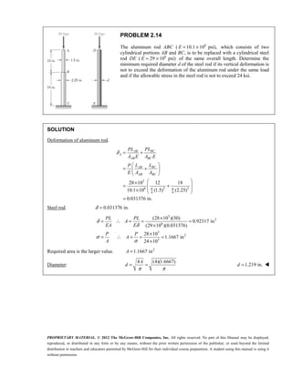
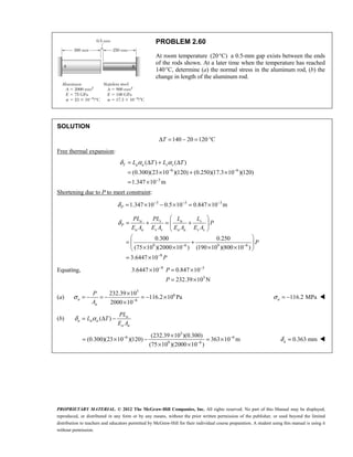
PROBLEM 2.71
In many situations, physical constraints prevent
strain from occurring in a given direction.
For example, 0
z
ε = in the case shown, where
longitudinal movement of the long prism is
prevented at every point. Plane sections
perpendicular to the longitudinal axis remain
plane and the same distance apart. Show that for
this situation, which is known as plane strain,
we can express ,
z
σ ,
εx and y
ε as follows:
2
2
( )
1
[(1 ) (1 ) ]
1
[(1 ) (1 ) ]
z x y
x x y
y y x
v
v v v
E
v v v
E
σ σ σ
ε σ σ
ε σ σ
= +
= − − +
= − − +
SOLUTION
1
0 ( ) or ( )
z x y z z x y
v v v
E
ε σ σ σ σ σ σ
= = − − + = +
2
2
1
( )
1
[ ( )]
1
[(1 ) (1 ) ]
x x y z
x y x y
x y
v v
E
v v
E
v v v
E
ε σ σ σ
σ σ σ σ
σ σ
= − −
= − − +
= − − +
2
2
1
( )
1
[ ( )]
1
[(1 ) (1 ) ]
y x y z
x y x y
y x
v v
E
v v
E
v v v
E
ε σ σ σ
σ σ σ σ
σ σ
= − + −
= − + − +
= − − + ](https://image.slidesharecdn.com/chapter02-220614132946-84c47c56/85/Chapter02-pdf-81-320.jpg)

![PROPRIETARY MATERIAL. © 2012 The McGraw-Hill Companies, Inc. All rights reserved. No part of this Manual may be displayed,
reproduced, or distributed in any form or by any means, without the prior written permission of the publisher, or used beyond the limited
distribution to teachers and educators permitted by McGraw-Hill for their individual course preparation. A student using this manual is using it
without permission.
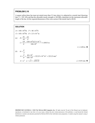
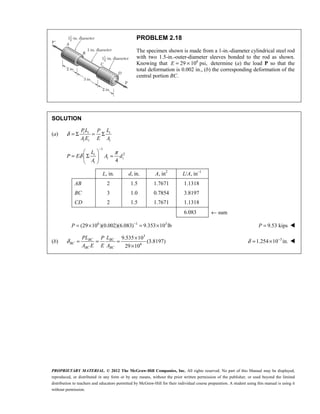
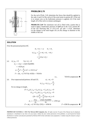
PROBLEM 2.73
For a member under axial loading, express the normal strain ε′ in a
direction forming an angle of 45° with the axis of the load in terms of the
axial strain εx by (a) comparing the hypotenuses of the triangles shown in
Fig. 2.49, which represent, respectively, an element before and after
deformation, (b) using the values of the corresponding stresses of σ′ and
σx shown in Fig. 1.38, and the generalized Hooke’s law.
SOLUTION
Figure 2.49
(a) 2 2 2
2 2 2 2
2 2 2 2
[ 2(1 )] (1 ) (1 )
2(1 2 ) 1 2 1 2
4 2 2 2
x x
x x x x
x x x x
v
v v
v v
ε ε ε
ε ε ε ε ε ε
ε ε ε ε ε ε
′
+ = + + −
′ ′
+ + = + + + − +
′ ′
+ = + − +
Neglect squares as small 4 2 2
x x
v
ε ε ε
′ = −
1
2
x
v
ε ε
−
′ =
(A) (B)](https://image.slidesharecdn.com/chapter02-220614132946-84c47c56/85/Chapter02-pdf-83-320.jpg)


![PROPRIETARY MATERIAL. © 2012 The McGraw-Hill Companies, Inc. All rights reserved. No part of this Manual may be displayed,
reproduced, or distributed in any form or by any means, without the prior written permission of the publisher, or used beyond the limited
distribution to teachers and educators permitted by McGraw-Hill for their individual course preparation. A student using this manual is using it
without permission.
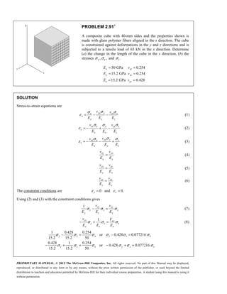
PROBLEM 2.89∗
The material constants E, G, k, and v are related by Eqs. (2.33) and (2.43). Show that any one of these
constants may be expressed in terms of any other two constants. For example, show that
(a) k = GE/(9G − 3E) and (b) v = (3k – 2G)/(6k + 2G).
SOLUTION
and
3(1 2 ) 2(1 )
E E
k G
v v
= =
− +
(a) 1 or 1
2 2
E E
v v
G G
+ = = −
2 2
3[2 2 4 ] 18 6
3 1 2 1
2
= = =
− + −
− −
E EG EG
k
G E G G E
E
G
9 6
=
−
EG
k
G E
(b)
2(1 )
3(1 2 )
k v
G v
+
=
−
3 6 2 2
3 2 2 6
− = +
− = +
k kv G Gv
k G G k
3 2
6 2
−
=
+
k G
v
k G
](https://image.slidesharecdn.com/chapter02-220614132946-84c47c56/85/Chapter02-pdf-100-320.jpg)
![PROPRIETARY MATERIAL. © 2012 The McGraw-Hill Companies, Inc. All rights reserved. No part of this Manual may be displayed,
reproduced, or distributed in any form or by any means, without the prior written permission of the publisher, or used beyond the limited
distribution to teachers and educators permitted by McGraw-Hill for their individual course preparation. A student using this manual is using it
without permission.
PROBLEM 2.90∗
Show that for any given material, the ratio G/E of the modulus of rigidity over the modulus of elasticity is
always less than 1
2
but more than 1
3
. [Hint: Refer to Eq. (2.43) and to Sec. 2.13.]
SOLUTION
or 2(1 )
2(1 )
E E
G v
v G
= = +
+
Assume 0
v > for almost all materials, and 1
2
<
v for a positive bulk modulus.
Applying the bounds,
1
2 < 2 1 3
2
E
G
≤ + =
Taking the reciprocals,
1 1
2 3
G
E
> >
or
1 1
3 2
G
E
< < ](https://image.slidesharecdn.com/chapter02-220614132946-84c47c56/85/Chapter02-pdf-101-320.jpg)
![PROPRIETARY MATERIAL. © 2012 The McGraw-Hill Companies, Inc. All rights reserved. No part of this Manual may be displayed,
reproduced, or distributed in any form or by any means, without the prior written permission of the publisher, or used beyond the limited
distribution to teachers and educators permitted by McGraw-Hill for their individual course preparation. A student using this manual is using it
without permission.
PROBLEM 2.91∗
(Continued)
Solving simultaneously, 0.134993
y z x
σ σ σ
= =
Using (4) and (5) in (1),
1 xy xz
x x y z
x x
v v
E E E
ε σ σ σ
= − −
2 6 2
3
6
6
3
6
9
1
[1 (0.254)(0.134993) (0.254)(0.134993)]
0.93142
(40)(40) 1600 mm 1600 10 m
65 10
40.625 10 Pa
1600 10
(0.93142)(40.625 10 )
756.78 10
50 10
x x
x
x
x
x
x
E
E
E
A
P
A
σ
σ
σ
ε
−
−
−
= − −
=
= = = ×
×
= = = ×
×
×
= = ×
×
(a) 6
(40 mm)(756.78 10 )
δ ε −
= = ×
x x x
L 0.0303 mm
δ =
x
(b) 6
40.625 10 Pa
σ = ×
x 40.6 MPa
σ =
x
6 6
(0.134993)(40.625 10 ) 5.48 10 Pa
σ σ
= = × = ×
y z 5.48 MPa
σ σ
= =
y z ](https://image.slidesharecdn.com/chapter02-220614132946-84c47c56/85/Chapter02-pdf-103-320.jpg)

![PROPRIETARY MATERIAL. © 2012 The McGraw-Hill Companies, Inc. All rights reserved. No part of this Manual may be displayed,
reproduced, or distributed in any form or by any means, without the prior written permission of the publisher, or used beyond the limited
distribution to teachers and educators permitted by McGraw-Hill for their individual course preparation. A student using this manual is using it
without permission.
PROBLEM 2.92∗
(Continued)
From Equation (1) with 0,
y
σ =
1 1
1 1
[ 0.254 ] [1 (0.254)(0.077216)]
0.98039
0.98039
zx xz
x x z x z
x z x x
x z x
x x
x
x
x x
x
v v
E E E E
E E
E
E
ε σ σ σ σ
σ σ σ
σ
ε
σ
= − = −
= − = −
=
=
But, 6
0.035 mm
875 10
40 mm
x
x
x
L
δ
ε −
= = = ×
(a)
9 6
3
(50 10 )(875 10 )
44.625 10 Pa
0.98039
σ
−
× ×
= = ×
x 44.6 MPa
σ =
x
0
y
σ =
6 6
(0.077216)(44.625 10 ) 3.446 10 Pa
σ = × = ×
z 3.45 MPa
σ =
z
From (2),
6 6
9 9
6
1
(0.254)(44.625 10 ) (0.428)(3.446 10 )
0
50 10 15.2 10
323.73 10
xy zy
y x y z
x y z
v v
E E E
ε σ σ σ
−
= + −
× ×
= − + −
× ×
= − ×
(b) 6
(40 mm)( 323.73 10 )
δ ε −
= = − ×
y y y
L 0.0129 mm
δ = −
y ](https://image.slidesharecdn.com/chapter02-220614132946-84c47c56/85/Chapter02-pdf-105-320.jpg)


![PROPRIETARY MATERIAL. © 2012 The McGraw-Hill Companies, Inc. All rights reserved. No part of this Manual may be displayed,
reproduced, or distributed in any form or by any means, without the prior written permission of the publisher, or used beyond the limited
distribution to teachers and educators permitted by McGraw-Hill for their individual course preparation. A student using this manual is using it
without permission.
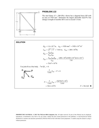
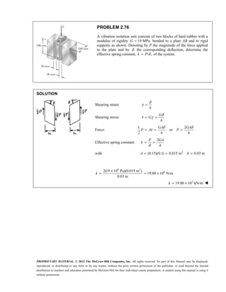
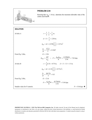
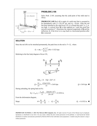
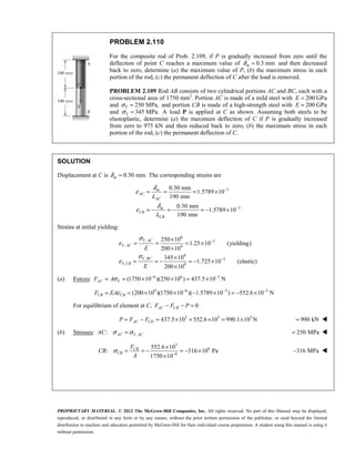
PROBLEM 2.113
The rigid bar ABC is supported by two links, AD and BE, of uniform
37.5 6-mm
× rectangular cross section and made of a mild steel that is
assumed to be elastoplastic with 200 GPa
E = and 250 MPa.
Y
σ =
The magnitude of the force Q applied at B is gradually increased from
zero to 260 kN. Knowing that 0.640 m,
a = determine (a) the value of
the normal stress in each link, (b) the maximum deflection of point B.
SOLUTION
Statics: 0: 0.640( ) 2.64 0
C BE AD
M Q P P
Σ = − − =
Deformation: 2.64 , 0.640
A B a
δ θ δ θ θ
= = =
Elastic analysis:
2 6 2
9 6
6
6 6
9
9 6
6
6 6
(37.5)(6) 225 mm 225 10 m
(200 10 )(225 10 )
26.47 10
1.7
(26.47 10 )(2.64 ) 69.88 10
310.6 10
(200 10 )(225 10 )
45 10
1.0
(45 10 )(0.640 ) 28.80 10
AD A A A
AD
AD
AD
BE B B B
BE
A
EA
P
L
P
A
EA
P
L
δ δ δ
θ θ
σ θ
δ δ δ
θ θ
σ
−
−
−
= = = ×
× ×
= = = ×
= × = ×
= = ×
× ×
= = = ×
= × = ×
9
128 10
BE
BE
P
A
θ
= = ×
From Statics,
2.64
4.125
0.640
BE AD BE AD
Q P P P P
= + = +
6 6 6
[28.80 10 (4.125)(69.88 10 ] 317.06 10
θ θ
= × + × = ×
Y
θ at yielding of link AD: 6 9
250 10 310.6 10
AD Y
σ σ θ
= = × = ×
6
6 6 3
804.89 10
(317.06 10 )(804.89 10 ) 255.2 10 N
Y
Y
Q
θ −
−
= ×
= × × = ×](https://image.slidesharecdn.com/chapter02-220614132946-84c47c56/85/Chapter02-pdf-129-320.jpg)

![PROPRIETARY MATERIAL. © 2012 The McGraw-Hill Companies, Inc. All rights reserved. No part of this Manual may be displayed,
reproduced, or distributed in any form or by any means, without the prior written permission of the publisher, or used beyond the limited
distribution to teachers and educators permitted by McGraw-Hill for their individual course preparation. A student using this manual is using it
without permission.
PROBLEM 2.114
Solve Prob. 2.113, knowing that a = 1.76 m and that the magnitude of
the force Q applied at B is gradually increased from zero to 135 kN.
PROBLEM 2.113 The rigid bar ABC is supported by two links, AD
and BE, of uniform 37.5 6-mm
× rectangular cross section and made
of a mild steel that is assumed to be elastoplastic with 200 GPa
E =
and 250 MPa.
Y
σ = The magnitude of the force Q applied at B is
gradually increased from zero to 260 kN. Knowing that 0.640 m,
a =
determine (a) the value of the normal stress in each link, (b) the
maximum deflection of point B.
SOLUTION
Statics: 0: 1.76( ) 2.64 0
C BE AD
M Q P P
Σ = − − =
Deformation: 2.64 , 1.76
A B
δ θ δ θ
= =
Elastic Analysis:
2 6 2
9 6
6
6 6
9
9 6
6
6 6
(37.5)(6) 225 mm 225 10 m
(200 10 )(225 10 )
26.47 10
1.7
(26.47 10 )(2.64 ) 69.88 10
310.6 10
(200 10 )(225 10 )
45 10
1.0
(45 10 )(1.76 ) 79.2 10
AD A A A
AD
AD
AD
BE B B B
BE
BE
A
EA
P
L
P
A
EA
P
L
δ δ δ
θ θ
σ θ
δ δ δ
θ θ
σ
−
−
−
= = = ×
× ×
= = = ×
= × = ×
= = ×
× ×
= = = ×
= × = ×
9
352 10
BE
P
A
θ
= = ×
From Statics,
2.64
1.500
1.76
BE AD BE AD
Q P P P P
= + = +
6 6 6
[73.8 10 (1.500)(69.88 10 ] 178.62 10
θ θ
= × + × = ×
Y
θ at yielding of link BE: 6 9
250 10 352 10
BE Y Y
σ σ θ
= = × = ×
6
6 6 3
710.23 10
(178.62 10 )(710.23 10 ) 126.86 10 N
Y
Y
Q
θ −
−
= ×
= × × = ×
Since 3
135 10 N ,
Y
Q Q
= × > link BE yields. 250 MPa
BE Y
σ σ
= =
6 6 3
(225 10 )(250 10 ) 56.25 10 N
σ −
= = × × = ×
BE Y
P A
](https://image.slidesharecdn.com/chapter02-220614132946-84c47c56/85/Chapter02-pdf-131-320.jpg)


![PROPRIETARY MATERIAL. © 2012 The McGraw-Hill Companies, Inc. All rights reserved. No part of this Manual may be displayed,
reproduced, or distributed in any form or by any means, without the prior written permission of the publisher, or used beyond the limited
distribution to teachers and educators permitted by McGraw-Hill for their individual course preparation. A student using this manual is using it
without permission.
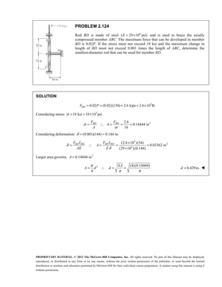
PROBLEM 2.132
A fabric used in air-inflated structures is subjected to a biaxial loading
that results in normal stresses 120
x
σ = MPa and 160
z
σ = MPa.
Knowing that the properties of the fabric can be approximated as
E = 87 GPa and v = 0.34, determine the change in length of (a) side AB,
(b) side BC, (c) diagonal AC.
SOLUTION
6
6
6 6 6
9
6 6 3
9
120 10 Pa,
0,
160 10 Pa
1 1
( ) [120 10 (0.34)(160 10 )] 754.02 10
87 10
1 1
( ) [ (0.34)(120 10 ) 160 10 ] 1.3701 10
87 10
σ
σ
σ
ε σ σ σ
ε σ σ σ
−
−
= ×
=
= ×
= − − = × − × = ×
×
= − − + = − × + × = ×
×
x
y
z
x x y z
z x y z
v v
E
v v
E
(a) 6
( ) (100 mm)(754.02 10 )
δ ε −
= = ×
AB x
AB 0.0754 mm
=
(b) 6
( ) (75 mm)(1.3701 10 )
δ ε −
= = ×
BC z
BC 0.1028 mm
=
Label sides of right triangle ABC as a, b, and c.
2 2 2
c a b
= +
Obtain differentials by calculus.
2 2 2
= +
= +
c dc a da b db
a b
dc da db
c c
But
2 2
100 mm,
75 mm,
(100 75 ) 125 mm
0.0754 mm
0.1370 mm
δ
δ
=
=
= + =
= =
= =
AB
BC
a
b
c
da
db
(c)
100 75
(0.0754) (0.1028)
125 125
δ = = +
AC dc 0.1220 mm
= ](https://image.slidesharecdn.com/chapter02-220614132946-84c47c56/85/Chapter02-pdf-153-320.jpg)


![01 01 chapgere[1]](https://cdn.slidesharecdn.com/ss_thumbnails/01-01chapgere1-130611230425-phpapp02-thumbnail.jpg?width=640&height=640&fit=bounds)