Download as PDF, PPTX


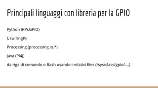
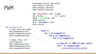
![IC2 #!/usr/bin/python
import smbus
bus = smbus.SMBus(1) # 0 oppure 1 se RPi è 256 o 512 Mb di RAM
DEVICE_ADDRESS = 0x70 # indirizzo 7 bit
DEVICE_REG_MODE1 = 0x00
DEVICE_REG_LEDOUT0 = 0x1d
#Scrive un singolo char [long write_byte_data(int addr,char cmd,char val)]
bus.write_byte_data(DEVICE_ADDRESS, DEVICE_REG_MODE1, 0x80)
#Lettura
(msb, lsb, xsb) = bus.read_i2c_block_data(addr, REG_MSB, 3)](https://image.slidesharecdn.com/prototiparecolraspberrypi-151216153310/85/Prototipare-col-raspberry-pi-19-320.jpg)
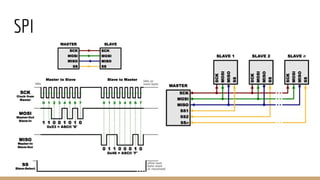
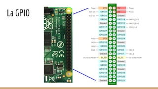
![SPI
#!/usr/bin/python
import spidev
import time
spi = spidev.SpiDev()
spi.open(0, 0)
spi.max_speed_hz = 7629
# Divide un intero in un array di 2 byte per spedirlo via SPI
def write_pot(input):
msb = input >> 8
lsb = input & 0xFF
spi.xfer([msb, lsb])
# Loop infinito di apertura/chiusura della porta del MCP4151
while True:
write_pot(0x1FF)
time.sleep(0.5)
write_put(0x00)
time.sleep(0.5)](https://image.slidesharecdn.com/prototiparecolraspberrypi-151216153310/85/Prototipare-col-raspberry-pi-25-320.jpg)
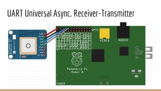
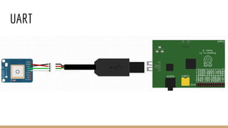
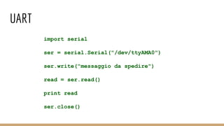

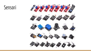
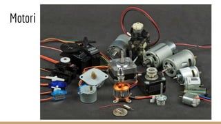
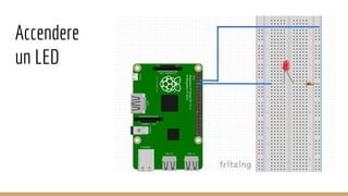
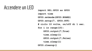
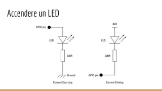
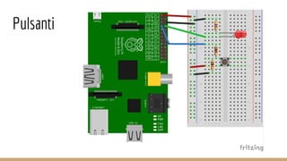
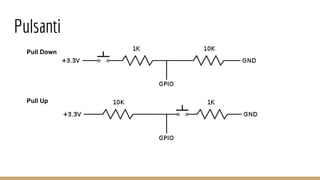
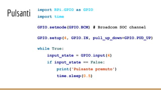
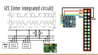
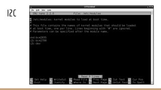
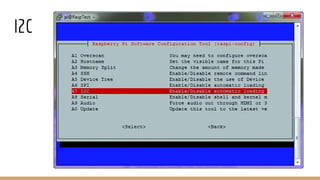
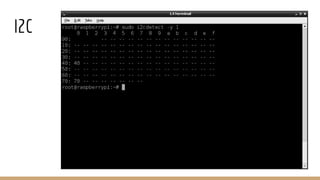
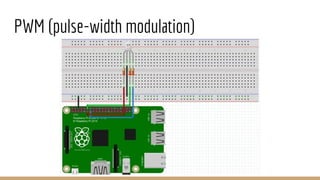
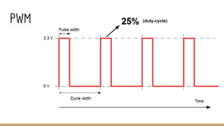
This document provides an overview of prototyping with a Raspberry Pi, including common operating systems, programming languages, GPIO pin usage, sensors, motors, I2C, PWM, SPI, and UART communication protocols. It discusses connecting an LED and button to the GPIO pins, as well as code examples for blinking an LED, reading a button press, and communicating via I2C, SPI, and UART. The online community is highlighted as a key benefit of the Raspberry Pi platform.


![[5]投影片 futurewad樹莓派研習會 141218](https://cdn.slidesharecdn.com/ss_thumbnails/5futurewad141218-141219162301-conversion-gate02-thumbnail.jpg?width=640&height=640&fit=bounds)